$34
Komatsu 6D105 Series Diesel Engine Shop Manual SEBE61360109 – PDF DOWNLOAD
Komatsu 6D105 Series Diesel Engine Shop Manual SEBE61360109 – PDF DOWNLOAD
FILE DETAILS:
Komatsu 6D105 Series Diesel Engine Shop Manual SEBE61360109 – PDF DOWNLOAD
Language : English
Pages : 350
Downloadable : Yes
File Type : PDF
Size: 21.7 MB
IMAGES PREVIEW OF THE MANUAL:
DESCRIPTION:
Komatsu 6D105 Series Diesel Engine Shop Manual SEBE61360109 – PDF DOWNLOAD
- The Komatsu 6D105 Series Diesel Engine Shop Manual SEBE61360109 is a comprehensive guidebook that provides detailed technical information and instructions on how to operate, maintain, and repair the Komatsu 6D105 series diesel engines. These engines are commonly used in heavy equipment such as excavators, bulldozers, and other heavy machinery.
- The manual is divided into several sections, each providing detailed information on specific topics. These sections include specifications, structure and function, testing and adjusting, disassembly and assembly, maintenance, and troubleshooting.
- The specifications section of the manual provides detailed information on the engine’s physical and operational characteristics, including its dimensions, weight, performance, and power output. It also provides information on the engine’s cooling system, fuel system, and lubrication system.
- The structure and function section of the manual provides an overview of the engine’s internal components and their functions. This section includes detailed diagrams and descriptions of the engine’s various components, such as the cylinder block, cylinder head, crankshaft, pistons, and valves.
- The testing and adjusting section of the manual provides instructions on how to test and adjust the engine’s various components to ensure they are functioning correctly. This section includes detailed procedures for testing and adjusting the engine’s fuel injection system, valve clearances, and oil pressure.
- The disassembly and assembly section of the manual provides step-by-step instructions on how to disassemble and reassemble the engine’s various components. This section includes detailed diagrams and photographs to guide the user through the process.
- The maintenance section of the manual provides information on routine maintenance tasks that should be performed to keep the engine in good working condition. This section includes instructions on how to perform tasks such as changing the engine oil and replacing the air filter.
- The troubleshooting section of the manual provides guidance on how to diagnose and resolve common issues that may arise with the engine. This section includes a list of common symptoms and their likely causes, as well as step-by-step instructions for troubleshooting and resolving each issue.
- Overall, the Komatsu 6D105 Series Diesel Engine Shop Manual SEBE61360109 is an essential resource for anyone who works with or operates machinery that utilizes these engine series. It provides a wealth of technical information, detailed instructions, and troubleshooting guidance that can help keep the engine running smoothly and extend its lifespan. The manual is designed to be user-friendly and easy to understand, with clear and concise language and illustrations to guide the user through each process. Whether you are a mechanic or an equipment operator, this manual will provide you with the information you need to keep your Komatsu engine in good working order.
TABLE OF CONTENTS:
Komatsu 6D105 Series Diesel Engine Shop Manual SEBE61360109 – PDF DOWNLOAD
COVER……………………………………………………………….. 1
CONTENTS…………………………………………………………….. 2
01 GENERAL…………………………………………………………… 19
GENERAL VIEW……………………………………………………… 20
SPECIFICATIONS……………………………………………………. 22
ASSEMBLY DRAWING………………………………………………….. 32
WEIGHT TABLE……………………………………………………… 44
PERFORMANCE CURVE…………………………………………………. 45
11 STRUCTURE AND FUNCTION……………………………………………… 75
GENERAL STRUCTURE…………………………………………………. 76
INTAKE AND EXHAUST SYSTEM………………………………………….. 80
INTAKE AND EXHAUST SYSTEM CHART…………………………………. 80
TURBOCHARGER………………………………………………….. 89
ENGINE BODY………………………………………………………. 91
CYLINDER HEAD…………………………………………………. 91
MAIN CIRCULATION PART (1/3)…………………………………….. 93
MAIN CIRCULATION PART (2/3)…………………………………….. 95
MAIN CIRCULATION PART (3/3)…………………………………….. 99
LUBRICATING SYSTEM…………………………………………………101
LUBRICATING SYSTEM CHART………………………………………..101
OIL PUMP………………………………………………………104
REGULATOR VALVE………………………………………………..106
OIL FILTER…………………………………………………….106
OIL COOLER…………………………………………………….107
FUEL SYSTEM……………………………………………………….109
FUEL SYSTEM CHART………………………………………………109
FOR CONSTRUCTION EQUIPMENT………………………………………110
FOR GENERATOR………………………………………………….112
FUEL INJECTION PUMP…………………………………………….114
GOVERNOR………………………………………………………118
FEED PUMP……………………………………………………..122
FUEL INJECTION NOZZLE…………………………………………..124
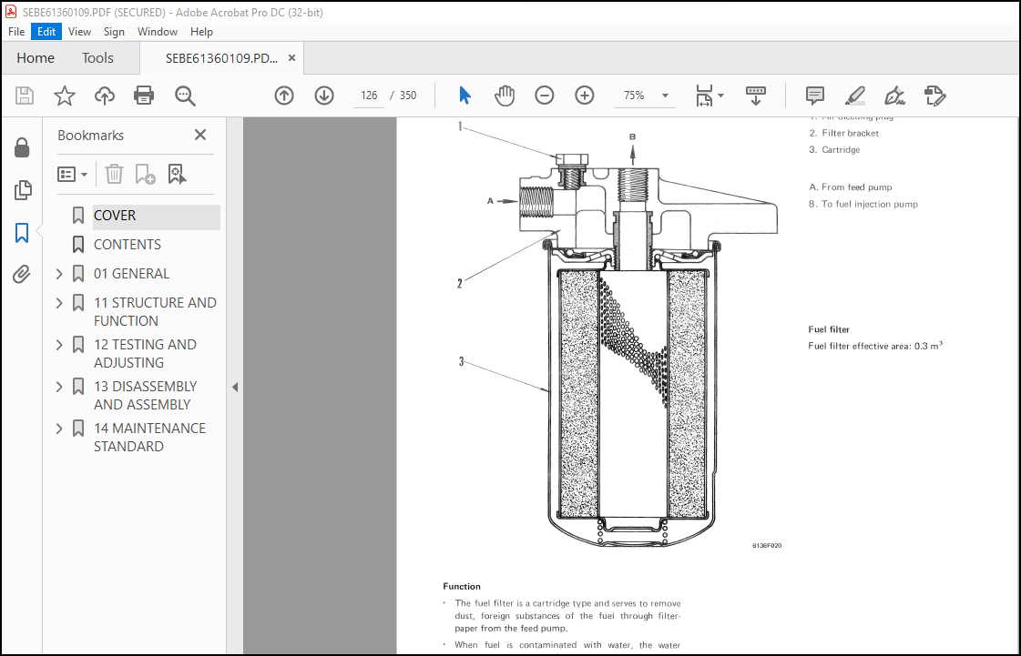
FUEL FILTER……………………………………………………126
FUEL CUT SOLENOID………………………………………………127
COOLING SYSTEM…………………………………………………….128
COOLING SYSTEM CHART……………………………………………128
WATER PUMP…………………………………………………….135
THERMOSTAT…………………………………………………….138
CORROSION RESISTOR……………………………………………..139
ELECTRICAL SYSTEM………………………………………………….140
WIRING DIAGRAM…………………………………………………140
ALTERNATOR…………………………………………………….141
STARTING MOTOR…………………………………………………145
SENSOR………………………………………………………..148
ACCESSORY…………………………………………………………151
AIR COMPRESSOR…………………………………………………151
12 TESTING AND ADJUSTING……………………………………………….153
GENERAL OF TESTING AND ADJUSTING ……………………………………154
MEASURING ENGINE SPEED………………………………………….154
CRANKING METHOD………………………………………………..155
INTAKE AND EXHAUST SYSTEM…………………………………………..156
CHECKING INTAKE AND EXHAUST SYSTEM……………………………….156
ADJUSTING VALVE CLEARANCE……………………………………….163
MEASURING EXHAUST COLOR (BOSCH TYPE)……………………………..164
ENGINE BODY……………………………………………………….165
MEASURING BLOW-BY………………………………………………165
MEASURING COMPRESSION PRESSURE…………………………………..166
CLEANING BREATHER ELEMENT……………………………………….167
LUBRICATING SYSTEM…………………………………………………168
CHECKING LUBRICATING SYSTEM……………………………………..168
REPLACEMENT AND CLEANING OF LUBRICATING SYSTEM…………………….176
MEASURING OIL CONSUMPTION……………………………………….180
FUEL SYSTEM……………………………………………………….182
CHECKING FUEL SYSTEM……………………………………………182
REPLACEMENT AND CLEANING OF COMPONENTS OF FUEL SYSTEM………………183
CHECKING FUEL INJECTION PUMP…………………………………….185
CHECKING AND ADJUSTMENT OF FUEL INJECTION NOZZLE…………………..186
TESTING AND ADJUSTING FUEL INJECTION TIMING ………………………188
ADJUSTING FUEL CUT SOLENOID (FOR WA300-1)…………………………190
CALIBRATION DATA……………………………………………….191
COOLING SYSTEM…………………………………………………….217
CHECKING COOLING SYSTEM…………………………………………217
REPLACEMENT AND CLEANING OF COMPONENTS OF COOLING SYSTEM……………220
CHECKING THERMOSTAT FUNCTION…………………………………….226
CHECKING AND ADJUSTMENT OF V-BELT TENSION AND REPLACEMENT OF V-BELT….227
PERFORMANCE TEST…………………………………………………..228
TESTING METHOD OF PERFORMANCE……………………………………228
RUN-IN CRITERIA………………………………………………..231
PERFORMANCE TEST CRITERIA……………………………………….236
TROUBLESHOOTING……………………………………………………246
TESTING AND ADJUSTING DATA………………………………………247
TESTING AND ADJUSTING TOOL LIST………………………………….250
METHOD OF READING TROUBLESHOOTING TABLE…………………………..251
TROUBLESHOOTING TABLE…………………………………………..253
1. STARTING DEFECTIVE OR BADNESS……………………………..253
2. ENGINE STOPPED DURING OPERATION……………………………256
3. ENGINE RUNS ABNORMALLY……………………………………257
4. FUEL CONSUMPTION TOO HIGH…………………………………257
5. LACK OF POWER……………………………………………258
6. EXHAUST GAS IS BLACK……………………………………..259
7. EXHAUST GAS IS BLUE………………………………………260
8. OIL CONSUMPTION TOO HIGH………………………………….261
9. OIL LEVEL RISES………………………………………….262
10. OL QUICKLY BECOMES DIRTY…………………………………263
11. ENGINE OIL PRESSURE GAUGE INDICATOR FLUCTUATES ABNORMALLY……264
12. LACK OF OIL PRESSURE…………………………………….265
13. OIL IN COOLING SYSTEM……………………………………266
14. WATER TEMPERATURE DOES NOT RISE…………………………..266
15. WATER TEMPERATURE RISES EXCESSIVELY……………………….267
16. TOO MUCH VIBRATION………………………………………268
17. ABNORMAL NOISE EMITTED…………………………………..269
18. EXCESSIVE WEAR OF ENGINE PARTS……………………………270
19. ENGINE DOES NOT START BECAUSE OF FAULT IN ELECTRICAL SYSTEM….271
20. BATTERY DOES NOT CHARGE………………………………….272
13 DISASSEMBLY AND ASSEMBLY…………………………………………….273
GENERAL…………………………………………………………..274
DISASSEMBLY……………………………………………………274
ASSEMBLY………………………………………………………290
DISASSEMBLY AND ASSEMBLY OF ACCESSORIES………………………………315
TURBOCHARGER…………………………………………………..315
OIL PUMP………………………………………………………323
WATER PUMP…………………………………………………….325
14 MAINTENANCE STANDARD………………………………………………..329
INTAKE AND EXHAUST SYSTEM…………………………………………..330
TURBOCHARGER…………………………………………………..330
ENGINE BODY……………………………………………………….331
CYLINDER HEAD………………………………………………….331
VALVES AND VALVE GUIDES…………………………………………332
ROCKER ARM SHAFT, PUSH-ROD AND TAPPET…………………………….334
CYLINDER BLOCK…………………………………………………335
CYLINDER LINER…………………………………………………337
CRANKSHAFT…………………………………………………….338
CAMSHAFT………………………………………………………340
TIMING GEAR……………………………………………………341
PISTON, PISTON RING, PISTON PIN………………………………….342
CONNECTING ROD…………………………………………………344
FLYWHEEL AND FLYWHEEL HOUSING……………………………………345
LUBRICATING SYSTEM…………………………………………………346
OIL PUMP………………………………………………………346
COOLING SYSTEM…………………………………………………….350
WATER PUMP, THERMOSTAT………………………………………….350
More products