$33
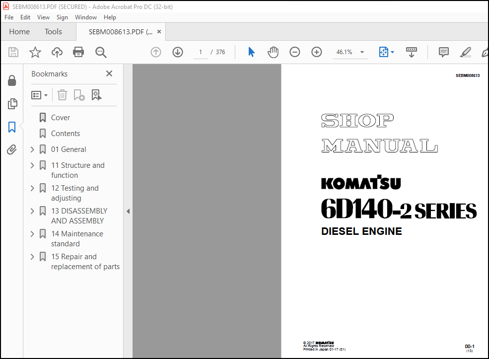
Komatsu 6D140-2 Series Diesel Engine Shop Manual SEBM008613 – PDF DOWNLOAD
Komatsu 6D140-2 Series Diesel Engine Shop Manual SEBM008613 – PDF DOWNLOAD
FILE DETAILS:
Komatsu 6D140-2 Series Diesel Engine Shop Manual SEBM008613 – PDF DOWNLOAD
Language : English
Pages : 376
Downloadable : Yes
File Type : PDF
Size: 21.2 MB
IMAGES PREVIEW OF THE MANUAL:
DESCRIPTION:
Komatsu 6D140-2 Series Diesel Engine Shop Manual SEBM008613 – PDF DOWNLOAD
The Komatsu 6D140-2 Series Diesel Engine Shop Manual SEBM008613 is a detailed guide that provides comprehensive information on the service, repair, and maintenance of the Komatsu 6D140-2 Series diesel engines. These engines are six-cylinder, turbocharged engines that are commonly used in heavy construction equipment, such as excavators and bulldozers.
The manual is published by Komatsu, a leading manufacturer of heavy equipment and construction machinery. The manual is designed to be used by mechanics and technicians who are responsible for maintaining and repairing Komatsu equipment. It is an essential tool for anyone who works with Komatsu engines.
The manual is divided into several sections, each of which provides specific information on different aspects of the engine. The sections include:
- General information: This section provides an overview of the engine, including its specifications, features, and operating principles. It also includes information on safety precautions, tools, and equipment needed for maintenance and repair.
- Inspection and adjustment: This section provides detailed instructions on how to inspect and adjust various components of the engine, including the cylinder head, valves, fuel system, and cooling system.
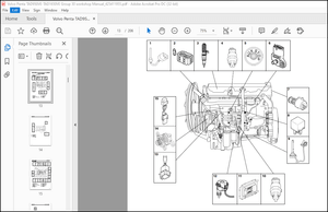
- Engine disassembly and assembly: This section provides step-by-step instructions on how to disassemble and assemble the engine. It includes detailed diagrams and illustrations to help users understand each step of the process.
- Troubleshooting: This section provides a comprehensive list of potential problems that may arise with the engine, along with diagnostic procedures to help identify and fix these issues.
- Maintenance: This section provides information on the regular maintenance tasks that should be performed on the engine, including oil changes, filter replacements, and other routine tasks.
- Reassembly and testing: This section provides detailed instructions on how to reassemble the engine after repairs have been made. It also includes information on how to test the engine to ensure that it is functioning properly.
- Service data: This section provides detailed technical data on the engine, including torque specifications, compression pressures, and other important information.
The manual is written in clear, concise language, and is filled with detailed diagrams and illustrations to help users understand each step of the process. It is an essential tool for anyone who works with Komatsu engines, and can help to ensure that the engine is maintained and repaired to the highest standards. It is important to note that the manual is designed for use by qualified mechanics and technicians, and should not be used by individuals without the appropriate training and experience.
TABLE OF CONTENTS:
Komatsu 6D140-2 Series Diesel Engine Shop Manual SEBM008613 – PDF DOWNLOAD
Cover……………………………………………………………………….. 1
Contents…………………………………………………………………….. 2
01 General…………………………………………………………………… 27
Applicable machine………………………………………………………… 28
Specifications……………………………………………………………. 30
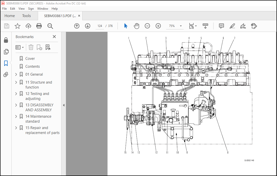
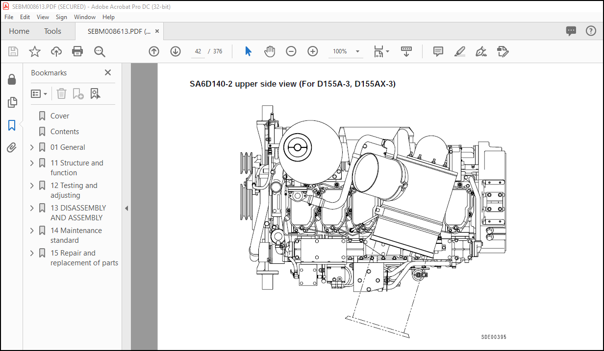
General assembly drawing…………………………………………………… 38
Weight table……………………………………………………………… 54
Engine performance curve…………………………………………………… 57
11 Structure and function……………………………………………………… 69
Intake and exhaust system………………………………………………….. 70
Intake and exhaust system………………………………………………. 70
Air cleaner…………………………………………………………… 83
Turbocharger………………………………………………………….. 86
Aftercooler…………………………………………………………… 88
Engine body………………………………………………………………. 92
Cylinder head…………………………………………………………. 92
Cylinder block………………………………………………………… 94
Main circulation system………………………………………………… 96
Vibration damper………………………………………………………. 98
Timing gear……………………………………………………………100
Valve system…………………………………………………………..102
Flywheel and flywheel housing……………………………………………104
Lubrication system…………………………………………………………106
Lubrication system chart………………………………………………..106
Oil pump………………………………………………………………108
Regulator valve and piston cooling valve………………………………….109
Oil filter…………………………………………………………….110
Oil cooler…………………………………………………………….114
Fuel system……………………………………………………………….116
Fuel system chart………………………………………………………116
Fuel injection pump…………………………………………………….118
Feed pump……………………………………………………………..126
Fuel injection nozzle…………………………………………………..127
Fuel filter……………………………………………………………128
Engine stop motor………………………………………………………129
Cooling system…………………………………………………………….134
Cooling system chart……………………………………………………134
Water pump…………………………………………………………….138
Thermostat…………………………………………………………….144
Corrosion resistor……………………………………………………..145
Corrosion resistor mounting……………………………………………..146
Cooling fan drive………………………………………………………147
Accessory…………………………………………………………………156
Air compressor…………………………………………………………156
Exhaust brake………………………………………………………….161
Electrical system………………………………………………………….165
Alternator…………………………………………………………….165
Starting motor…………………………………………………………172
Electrical intake air heater…………………………………………….177
Front PTO mounting……………………………………………………..178
Front PTO assembly……………………………………………………..179
Front PTO drive gear assembly……………………………………………180
12 Testing and adjusting……………………………………………………….181
Mounting (adjusting) methodof engine speed sensor……………………………..182
Engine body……………………………………………………………….183
Adjusting valve clearance……………………………………………….183
Measuring compressionpressure……………………………………………184
Fuel system……………………………………………………………….185
Testing and adjusting fuelinjection timing………………………………..185
Adjusting fuel injectionpressure…………………………………………186
Procedure for adjustingengine stop motor cable…………………………….187
Cooling system…………………………………………………………….189
Checking and adjusting fan belt tension…………………………………..189
Fuel injection pump calibration data…………………………………………190
Performance test…………………………………………………………..206
Run-in standard………………………………………………………..206
Performance test criteria……………………………………………….212
Troubleshooting……………………………………………………………221
Points to remember when troubleshooting…………………………………..223
Method of using troubleshooting charts……………………………………224
S-1 Starting performance is poor (starting always takes time)……………….228
S-2 Engine does not start……………………………………………….229
S-3 Engine does not pick up smoothly (follow-up is poor)……………………232
S-4 Engine stops during operations……………………………………….233
S-5 Engine does not rotate smoothly (hunting)……………………………..234
S-6 Engine lacks output (no power)……………………………………….235
S-7 Exhaust smoke is black (incomplete combustion)…………………………236
S-8 Oil consumption is excessive (or exhaust smoke is blue)…………………237
S-9 Oil becomes contaminated quickly……………………………………..238
S-10 Fuel consumption is excessive……………………………………….239
S-11 Oil is in cooling water, or water spurts back, or water level goes down….240
S-12 Oil pressure caution lamp lights up (drop in oil pressure)……………..241
S-13 Oil level rises (water, fuel in oil)…………………………………242
S-14 Water temperature becomes too high (overheating)………………………243
S-15 Abnormal noise is made……………………………………………..244
S-16 Vibration is excessive……………………………………………..245
Testing and adjusting tool list………………………………………….247
Testing and adjusting dataa……………………………………………..248
13 DISASSEMBLY AND ASSEMBLY…………………………………………………….257
GENERAL DISASSEMBLY………………………………………………………..257
Air cleaner・muffler…………………………………………………….258
Starting motor…………………………………………………………258
Turbocharger drain tube…………………………………………………259
Setting engine in engine overhaul stand…………………………………..259
Corrosion resistor, air compressor suction tube……………………………259
Bracket……………………………………………………………….259
Connector……………………………………………………………..260
Tension pulley assembly…………………………………………………260
Fan pulley assembly…………………………………………………….260
Alternator assembly・pulley………………………………………………260
Dipstick guide, air compressor…………………………………………..261
Fuel hose……………………………………………………………..261
Turbocharger…………………………………………………………..261
Exhaust manifold……………………………………………………….261
After-cooler assembly (Intake manifold assembly)…………………………..261
Fuel injection tube…………………………………………………….261
Fuel injection pump assembly…………………………………………….262
Tube, bracket, PTO case…………………………………………………262
Fuel filter・fuel filter bracket………………………………………….262
Oil filter・oil regulator………………………………………………..262
Oil pan……………………………………………………………….263
Suction pipe, under frame……………………………………………….263
Flywheel………………………………………………………………263
Rear seal……………………………………………………………..263
Flywheel housing……………………………………………………….264
Air vent tube, spill pipe, rocker arm housing cover………………………..264
Nozzle holder, inlet connector…………………………………………..265
Rocker arm…………………………………………………………….265
Push rod………………………………………………………………266
Crosshead……………………………………………………………..266
Rocker arm housing……………………………………………………..266
Cylinder head assembly………………………………………………….266
Vibration damper・crankshaft pulley assembly……………………………….267
Front support………………………………………………………….267
Thermostat housing……………………………………………………..267
Water pump assembly…………………………………………………….267
Oil cooler assembly…………………………………………………….267
Cam follower…………………………………………………………..268
Gear case cover………………………………………………………..268
Injection pump drive gear……………………………………………….268
Camshaft………………………………………………………………268
Oil pump assembly, oil pump idler gear……………………………………269
Main idler gear, injection pump drive shaft……………………………….269
Piston cooling nozzle…………………………………………………..269
Piston and connecting rod assembly……………………………………….269
Crankshaft…………………………………………………………….271
Cylinder liner…………………………………………………………272
GENERAL ASSEMBLY…………………………………………………………..273
Tightening bolts by the plastic range turning angle method………………….274
Drawing of special tool…………………………………………………275
Preparatory work……………………………………………………….276
Cylinder liner…………………………………………………………277
Crankshaft…………………………………………………………….279
Piston and connecting rod assembly……………………………………….282
Piston cooling nozzle…………………………………………………..284
Main idler gear, fuel injection pump drive shaft…………………………..285
Oil pump idler gear, oil pump assembly……………………………………286
Camshaft………………………………………………………………286
Fuel injection pump drive gear…………………………………………..286
Fuel injection pump drive shaft oil seal………………………………….287
Gear case cover………………………………………………………..288
Breather………………………………………………………………288
Front seal…………………………………………………………….289
Cam follower…………………………………………………………..290
Oil cooler assembly…………………………………………………….290
Water pump assembly…………………………………………………….291
Thermostat housing……………………………………………………..291
Front support………………………………………………………….291
Vibration damper, crankshaft pulley assembly………………………………291
Cylinder head assembly………………………………………………….292
Crosshead……………………………………………………………..294
Rocker arm housing……………………………………………………..294
Push rod………………………………………………………………294
Rocker arm…………………………………………………………….295
Adjusting valve clearance……………………………………………….295
Nozzle holder, inlet connector…………………………………………..296
Rocker arm housing cover, spill pipe, air vent tube………………………..297
Flywheel housing……………………………………………………….297
Rear seal……………………………………………………………..298
Flywheel………………………………………………………………301
Suction pipe…………………………………………………………..302
Oil pan……………………………………………………………….302
Oil filter assembly, oil regulator……………………………………….302
Fuel filter assembly・fuel filter bracket………………………………….302
PTO case tube, bracket………………………………………………….303
Fuel injection pump assembly…………………………………………….303
Adjusting fuel injection pump……………………………………………304
Fuel injection tube…………………………………………………….306
After-cooler assembly (Intake manifold assembly)…………………………..306
Exhaust manifold……………………………………………………….306
Turbocharger…………………………………………………………..307
Fuel hose……………………………………………………………..307
Dipstick guide, air compressor…………………………………………..307
Alternator assembly, pulley……………………………………………..307
Fan pulley assembly…………………………………………………….308
Tension pulley assembly…………………………………………………308
Intake connector……………………………………………………….308
Muffler bracket, air cleaner bracket……………………………………..308
Corrosion resistor……………………………………………………..309
Resetting engine in engine stand…………………………………………309
Turbocharger drain tube…………………………………………………309
Starting motor…………………………………………………………309
Air cleaner, muffler……………………………………………………310
Refilling with oil……………………………………………………..310
14 Maintenance standard………………………………………………………..311
Intake and exhaust system…………………………………………………..312
Turbocharger…………………………………………………………..312
Engine body……………………………………………………………….316
Cylinder head………………………………………………………….316
Valve, valve guide……………………………………………………..318
Rocker arm and shaft……………………………………………………320
Crosshead and guide…………………………………………………….321
Cylinder block…………………………………………………………322
Cylinder liner…………………………………………………………323
Crankshaft…………………………………………………………….324
Camshaft………………………………………………………………325
Cam follower and push rod……………………………………………….326
Timing gear……………………………………………………………328
Piston………………………………………………………………..330
Connecting rod…………………………………………………………332
Flywheel and flywheel housing……………………………………………333
Lubrication system…………………………………………………………334
Oil pump………………………………………………………………334
Regulator valve, piston cooling valve and safety valve……………………..336
Oil cooler…………………………………………………………….337
Cooling system…………………………………………………………….338
Water pump…………………………………………………………….338
Thermostat…………………………………………………………….341
15 Repair and replacement of parts………………………………………………343
Table of special tools……………………………………………………..344
Cylinder head……………………………………………………………..345
Grinding of fitting face ofcylinder head………………………………….345
Replacing valve seat insert……………………………………………..346
Pressure test………………………………………………………….351
Replacing valve guide…………………………………………………..352
Replacing crosshead guide……………………………………………….353
Grinding valve…………………………………………………………354
Cylinder block…………………………………………………………….355
Replacing cam bushing…………………………………………………..355
Replacing crankshaft gear……………………………………………….358
Replacing cam gear……………………………………………………..359
Replacing flywheel ring gear…………………………………………….360
Replacing connecting rodsmall end bushing…………………………………361
Cylinder block parts……………………………………………………362
Testing and inspecting cylinder block…………………………………….363
Correcting cylinder block top surface, counterbore…………………………366
Replacing main bearing cap………………………………………………374
More products