$32
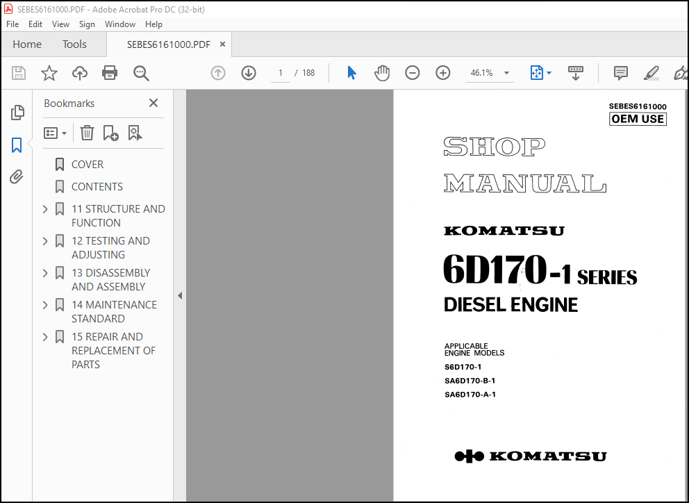
Komatsu 6D170-1 Series Diesel Engine Shop Manual SEBES6161000 – PDF DOWNLOAD
Komatsu 6D170-1 Series Diesel Engine Shop Manual SEBES6161000 – PDF DOWNLOAD
FILE DETAILS:
Komatsu 6D170-1 Series Diesel Engine Shop Manual SEBES6161000 – PDF DOWNLOAD
Language : English
Pages : 188
Downloadable : Yes
File Type : PDF
Size: 17 MB
IMAGES PREVIEW OF THE MANUAL:
DESCRIPTION:
Komatsu 6D170-1 Series Diesel Engine Shop Manual SEBES6161000 – PDF DOWNLOAD
The Komatsu 6D170-1 Series Diesel Engine Shop Manual SEBES6161000 is a comprehensive guide that provides detailed information on the maintenance, repair, and overhaul of the 6D170-1 series engine. This engine is used in a variety of Komatsu equipment, including bulldozers, excavators, and other heavy equipment.
- The manual is organized into several sections, each covering a different aspect of the engine. The first section provides an overview of the engine, including its specifications and performance data. This section also includes a table of contents, a list of illustrations, and a list of symbols and abbreviations used throughout the manual.
- The second section of the manual covers engine inspection and measurement procedures. This section provides step-by-step instructions for checking and measuring various components of the engine, including the cylinder block, crankshaft, and connecting rods. The manual includes detailed illustrations to help the reader understand the procedures.
- The third section covers engine disassembly and assembly procedures. This section provides instructions for removing and installing various components of the engine, including the cylinder head, pistons, and crankshaft. The manual also includes torque specifications for each component.
- The fourth section covers engine testing and adjusting procedures. This section provides instructions for testing and adjusting various components of the engine, including the fuel injection system, the turbocharger, and the valve clearance. The manual includes detailed illustrations to help the reader understand the procedures.
- The fifth section covers engine maintenance procedures, including routine maintenance and inspections. This section provides instructions for maintaining the engine to ensure its continued performance and longevity.
- The sixth section covers engine troubleshooting and diagnosis procedures. This section provides instructions for diagnosing and troubleshooting various engine problems, including starting problems, low power output, and excessive smoke. The manual includes a troubleshooting chart and detailed illustrations to help the reader diagnose and fix the problem.
- Overall, the Komatsu 6D170-1 Series Diesel Engine Shop Manual SEBES6161000 is an essential tool for anyone working on or maintaining this engine. The manual is available in print or digital formats, making it a convenient and accessible resource for mechanics and technicians. It is designed to be user-friendly and easy to understand, with clear instructions and detailed illustrations. With this manual, you can ensure that your Komatsu equipment is operating at its best and avoid costly repairs and downtime.
TABLE OF CONTENTS:
Komatsu 6D170-1 Series Diesel Engine Shop Manual SEBES6161000 – PDF DOWNLOAD
COVER………………………………………………………………… 1
CONTENTS……………………………………………………………… 2
11 STRUCTURE AND FUNCTION………………………………………………. 11
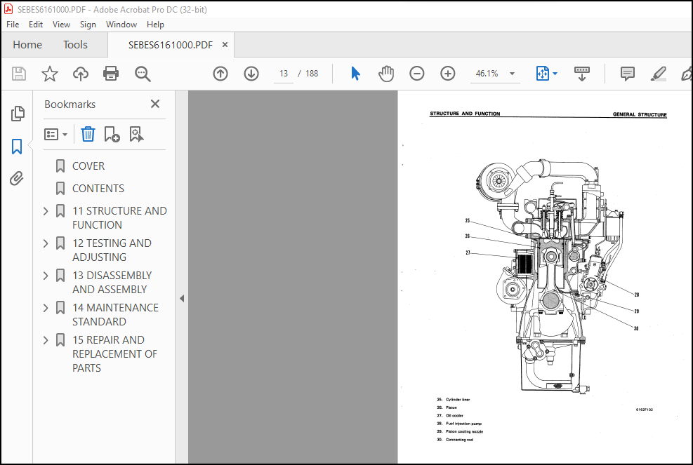
GENERAL STRUCTURE………………………………………………….. 12
INTAKE AND EXHAUST SYSTEM…………………………………………… 14
INTAKE AND EXHAUST SYSTEM……………………………………….. 14
TURBOCHARGER…………………………………………………… 21
AFTER-COOLER…………………………………………………… 25
ENGINE BODY……………………………………………………….. 26
CYLINDER HEAD………………………………………………….. 26
VALVE SYSTEM…………………………………………………… 28
CYLINDER BLOCK…………………………………………………. 30
MAIN CIRCULATION PART…………………………………………… 32
TIMING GEAR……………………………………………………. 34
FLYWHEEL AND FLYWHEEL HOUSING……………………………………. 36
LUBRICATION SYSTEM…………………………………………………. 37
LUBRICATION SYSTEM CHART………………………………………… 37
OIL PUMP………………………………………………………. 38
OIL FILTER AND SAFETY VALVE……………………………………… 39
OIL COOLER…………………………………………………….. 40
MAIN RELIEF VALVE………………………………………………. 42
OIL COOLER BY-PASS VALVE………………………………………… 42
PISTON COOLING VALVE……………………………………………. 43
MECHANICAL PUMP………………………………………………… 44
FUEL SYSTEM……………………………………………………….. 45
FUEL SYSTEM CHART………………………………………………. 45
FUEL INJECTION PUMP…………………………………………….. 46
FUEL INJECTION NOZZLE…………………………………………… 50
FUEL INJECTION PUMP DRIVE……………………………………….. 51
FUEL FILTER……………………………………………………. 52
FUEL SOLENOID………………………………………………….. 53
ENGINE STOP MOTOR………………………………………………. 55
STARTING AID…………………………………………………… 60
COOLING SYSTEM…………………………………………………….. 61
COOLING SYSTEM CHART……………………………………………. 61
WATER PUMP…………………………………………………….. 62
FAN DRIVE AND TENSION PULLEY…………………………………….. 63
CORROSION RESISTOR……………………………………………… 67
THERMOSTAT…………………………………………………….. 68
ACCESSORY…………………………………………………………. 69
AIR COMPRESSOR MOUNTING…………………………………………. 69
AIR COMPRESSOR…………………………………………………. 70
ELECTRICAL SYSTEM………………………………………………….. 71
ALTERNATOR…………………………………………………….. 71
STARTING MOTOR…………………………………………………. 73
12 TESTING AND ADJUSTING……………………………………………….. 74
FUEL SYSTEM……………………………………………………….. 75
ADJUSTING FUEL SOLENOID…………………………………………. 75
ADJUSTING ENGINE STOP MOTOR……………………………………… 76
ADJUSTING FUEL INJECTION PRESSURE………………………………… 77
TESTING AND ADJUSTING TOOL LIST………………………………….. 80
TROUBLESHOOTING……………………………………………………. 81
METHOD OF READING TROUBLESHOOTING TABLE…………………………… 82
TROUBLESHOOTING TABLE…………………………………………… 84
1. STARTING DEFECTIVE OR BADNESS……………………………… 84
2. ENGINE STOPPED DURING OPERATION……………………………. 87
3. ENGINE RUNS ABNORMALLY……………………………………. 88
4. FUEL CONSUMPTION TOO HIGH…………………………………. 88
5. LACK OF POWER……………………………………………. 89
6. EXHAUST GAS IS BLACK……………………………………… 90
7. EXHAUST GAS IS BLUE………………………………………. 91
8. OIL CONSUMPTION TOO HIGH………………………………….. 92
9. OIL LEVEL RISES………………………………………….. 93
10. OIL QUICKLY BECOMES DIRTY………………………………… 94
11. ENGINE OIL PRESSURE GAUGE INDICATOR FLUCTUATES ABNORMALLY……. 95
12. LACK OF OIL PRESSURE…………………………………….. 96
13. OIL IN COOLING SYSTEM……………………………………. 97
14. WATER TEMPERATURE DOES NOT RISE…………………………… 97
15. WATER TEMPERATURE RISES EXCESSIVELY……………………….. 98
16. TOO MUCH VIBRATION………………………………………. 99
17. ABNORMAL NOISE EMITTED……………………………………100
18. EXCESSIVE WEAR OF ENGINE PARTS…………………………….101
19. ENGINE DOES NOT START BECAUSE OF FAULT IN ELECTRICAL SYSTEM…..102
20. BATTERY DOES NOT CHARGE…………………………………..103
13 DISASSEMBLY AND ASSEMBLY……………………………………………..104
GENERAL……………………………………………………………106
DISASSEMBLY…………………………………………………….106
ASSEMBLY……………………………………………………….124
14 MAINTENANCE STANDARD…………………………………………………148
TURBOCHARGER……………………………………………………….149
CYLINDER HEAD………………………………………………………153
VALVES AND VALVE GUIDE………………………………………………154
CROSSHEAD AND CROSSHEAD GUIDE………………………………………..155
PUSH ROD AND CAM FOLLOWER……………………………………………156
CYLINDER BLOCK……………………………………………………..157
CYLINDER LINER……………………………………………………..159
CRANKSHAFT…………………………………………………………160
CAMSHAFT…………………………………………………………..161
TIMING GEAR………………………………………………………..162
PISTON, PISTON RING AND PISTON PIN……………………………………163
CONNECTING ROD……………………………………………………..164
OIL PUMP…………………………………………………………..165
OIL PUMP RELIEF VALVE, PISTON COOLING VALVE AND OIL COOLER BY-PASS VALVE….166
AIR COMPRESSOR……………………………………………………..167
WATER PUMP…………………………………………………………169
15 REPAIR AND REPLACEMENT OF PARTS……………………………………….170
REPAIRING MOUNTING FACE OF CYLINDER HEAD BY GRINDING……………………171
REPLACING VALVE SEAT INSERTS…………………………………………172
REPLACING NOZZLE HOLDER SLEEVE……………………………………….176
REPLACING VALVE GUIDE……………………………………………….179
REPLACING CROSS HEAD GUIDE…………………………………………..180
GRINDING THE VALVE………………………………………………….180
GRINDING THE TOP SURFACE OF CYLINDER BLOCK…………………………….181
REPLACING MAIN METAL CAP…………………………………………….182
REPAIRING THE CRANKSHAFT…………………………………………….183
REPLACING CAM BUSHING……………………………………………….187
REPLACING CRANK GEAR………………………………………………..188
REPLACING CAM GEAR………………………………………………….188
REPLACING FLYWHEEL RING GEAR…………………………………………188
More products