$36
Komatsu 70E-5 76E-5 Series Diesel Engine Shop Manual SEBM037701 – PDF DOWNLOAD
Komatsu 70E-5 76E-5 Series Diesel Engine Shop Manual SEBM037701 – PDF DOWNLOAD
FILE DETAILS:
Komatsu 70E-5 76E-5 Series Diesel Engine Shop Manual SEBM037701 – PDF DOWNLOAD
Language : English
Pages : 144
Downloadable : Yes
File Type : PDF
Size: 35.3 MB
IMAGES PREVIEW OF THE MANUAL:
DESCRIPTION:
Komatsu 70E-5 76E-5 Series Diesel Engine Shop Manual SEBM037701 – PDF DOWNLOAD
The Komatsu 70E-5 76E-5 Series Diesel Engine Shop Manual SEBM037701 is a comprehensive guide that provides detailed information on the repair and maintenance of the 70E-5 and 76E-5 series diesel engines. The manual is designed for use by mechanics and technicians who are responsible for servicing and repairing the engines.
- The manual begins with an overview of the 70E-5 and 76E-5 series diesel engines, including their specifications, design features, and performance characteristics. This section provides a detailed description of the engine’s construction and operation, as well as an overview of the various components that make up the engine.
- The manual then provides detailed instructions on the disassembly, inspection, repair, and reassembly of the various components of the 70E-5 and 76E-5 series engines. This section covers topics such as the cylinder block, cylinder head, crankshaft, pistons, connecting rods, camshaft, and timing gears.
- The cylinder block section provides detailed instructions on the removal and installation of the cylinder block, as well as instructions for inspection, repair, and reassembly of various cylinder block components, such as the cylinder liners and main bearings. The cylinder head section covers the inspection, repair, and replacement of various cylinder head components, such as valves, springs, and guides. The crankshaft section provides instructions on the inspection, repair, and replacement of various crankshaft components, such as the main and connecting rod bearings. The piston section covers the inspection, repair, and replacement of various piston components, such as rings and wrist pins. The connecting rod section provides instructions on the inspection, repair, and replacement of various connecting rod components, such as bearings and bolts. The camshaft and timing gears section covers the inspection, repair, and replacement of various camshaft and timing gear components, such as bearings, gears, and chains.
- The manual also includes a section on troubleshooting, which provides detailed instructions on how to diagnose and fix common problems that may occur during the operation of the 70E-5 and 76E-5 series engines. This section includes a list of common symptoms, possible causes, and recommended solutions for each problem.
- In addition to these repair and maintenance procedures, the manual includes several important safety sections. These cover topics such as engine safety, electrical safety, and hydraulic safety, and provide detailed instructions on how to handle emergencies and prevent accidents and injuries.
- Overall, the Komatsu 70E-5 76E-5 Series Diesel Engine Shop Manual SEBM037701 is an essential resource for mechanics and technicians who are responsible for the repair and maintenance of these powerful engines. It provides detailed information on how to disassemble, inspect, repair, and reassemble the engine’s various components, as well as important safety information to help prevent accidents and injuries.
TABLE OF CONTENTS:
Komatsu 70E-5 76E-5 Series Diesel Engine Shop Manual SEBM037701 – PDF DOWNLOAD
COVER………………………………………………………………….. 1
CONTENTS……………………………………………………………….. 15
1. GENERAL……………………………………………………………… 16
1.1 SPECIFICATIONS…………………………………………………… 17
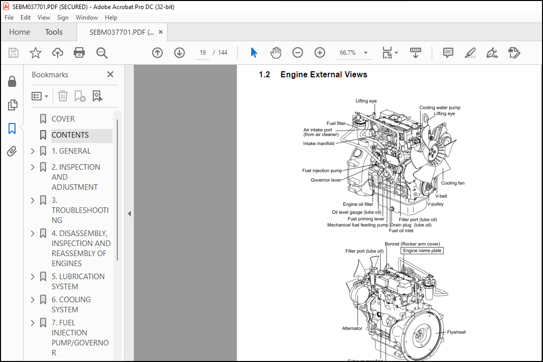
1.2 ENGINE EXTERNAL VIEWS…………………………………………….. 19
1.3 STRUCTURAL DESCRIPTION……………………………………………. 20
2. INSPECTION AND ADJUSTMENT……………………………………………… 21
2.1 PERIODIC MAINTENANCE SCHEDULE……………………………………… 22
2.2 PERIODIC INSPECTION AND MAINTENANCE PROCEDURE……………………….. 23
2.2.1 CHECK BEFORE DAILY OPERATION ………………………………… 23
2.2.2 INSPECTION AFTER INITIAL 50 HOURS OPERATION …………………… 25
2.2.3 INSPECTION EVERY 50 HOURS……………………………………. 28
2.2.4 INSPECTION EVERY 250 HOURS OR 3 MONTHS………………………… 32
2.2.5 INSPECTION EVERY 500 HOURS OR 6 MONTHS………………………… 35
2.2.6 INSPECTION EVERY 1,000 HOURS OR ONE YEAR………………………. 37
2.2.7 INSPECTION EVERY 2000 HOURS OR 2 YEARS………………………… 43
2.3 ADJUSTING THE NO-LOAD MAXIMUM OR MINIMUM SPEED………………………. 45
2.4 SENSOR INSPECTION………………………………………………… 46
2.4.1 OIL PRESSURE SWITCH…………………………………………. 46
2.4.2 THERMO SWITCH………………………………………………. 46
2.5 WATER LEAK CHECK IN COOLING WATER SYSTEM……………………………. 46
2.6 RADIATOR CAP INSPECTION…………………………………………… 47
2.7 THERMOSTAT INSPECTION ……………………………………………. 47
2.8 ADJUSTING OPERATION ……………………………………………… 48
2.9 LONG STORAGE…………………………………………………….. 48
3. TROUBLESHOOTING………………………………………………………. 49
3.1 PREPARATION BEFORE TROUBLESHOOTING…………………………………. 50
3.2 QUICK REFERENCE TABLE FOR TROUBLESHOOTING ……………………….. 51
3.3 TROUBLESHOOTING BY MEASURING COMPRESSION PRESSURE……………………. 54
4. DISASSEMBLY, INSPECTION AND REASSEMBLY OF ENGINES………………………… 56
4.1 COMPLETE DISASSEMBLY AND REASSEMBLY………………………………… 57
4.1.1 INTRODUCTION……………………………………………….. 57
4.1.2 SPECIAL SERVICE TOOLS……………………………………….. 58
4.1.3 COMPLETE DISASSEMBLY………………………………………… 63
4.1.4 PRECAUTIONS BEFORE AND DURING REASSEMBLY………………………. 67
4.1.5 ADJUSTING OPERATION ………………………………………… 67
4.2 CYLINDER HEAD: DISASSEMBLY, INSPECTION AND REASSEMBLY………………… 68
4.2.1 COMPONENTS (2-VALVE CYLINDER HEAD)……………………………. 68
4.2.2 DISASSEMBLY PROCEDURE……………………………………….. 69
4.2.3 REASSEMBLY PROCEDURE………………………………………… 69
4.2.4 SERVICING POINTS……………………………………………. 70
4.2.5 PARTS INSPECTION AND MEASUREMENT……………………………… 74
4.2.6 VALVE SEAT CORRECTION ………………………………………. 78
4.2.7 VALVE GUIDE REPLACEMENT …………………………………….. 79
4.2.8 VALVE STEM SEAL REPLACEMENT………………………………….. 80
4.3 GEAR TRAIN AND CAMSHAFT…………………………………………… 81
4.3.1 COMPONENTS…………………………………………………. 81
4.3.2 DISASSEMBLY PROCEDURE……………………………………….. 81
4.3.3 REASSEMBLY PROCEDURE………………………………………… 82
4.3.4 SERVICING POINTS……………………………………………. 82
4.3.5 PARTS INSPECTION AND MEASUREMENT …………………………….. 85
4.3.6 OIL SEAL REPLACEMENT (GEAR CASE SIDE)…………………………. 86
4.3.7 CAMSHAFT BUSHING REPLACEMENT ………………………………… 86
4.4 CYLINDER BLOCK…………………………………………………… 87
4.4.1 COMPONENTS…………………………………………………. 87
4.4.2 DISASSEMBLY PROCEDURE……………………………………….. 88
4.4.3 REASSEMBLY PROCEDURE………………………………………… 88
4.4.4 SERVICING POINTS……………………………………………. 88
4.4.5 PARTS INSPECTION AND MEASUREMENT……………………………… 92
4.4.6 CYLINDER BORE CORRECTION……………………………………..101
4.4.7 PISTON PIN METAL REPLACEMENT …………………………………102
4.4.8 OIL SEAL REPLACEMENT (FLYWHEEL HOUSING SIDE)……………………102
5. LUBRICATION SYSTEM ……………………………………………………103
5.1 LUBRICATION SYSTEM DIAGRAM…………………………………………104
5.2 TROCHOID PUMP COMPONENTS…………………………………………..105
5.3 DISASSEMBLY (REVERSE THE PROCEDURE BELOW FOR ASSEMBLY)………………..105
5.4 SERVICING POINTS………………………………………………….105
5.5 PARTS INSPECTION AND MEASUREMENT …………………………………..106
6. COOLING SYSTEM ……………………………………………………….107
6.1 COOLING WATER SYSTEM ……………………………………………..108
6.2 COOLING WATER PUMP COMPONENTS………………………………………108
6.3 DISASSEMBLY (REVERSE THE PROCEDURE BELOW FOR ASSEMBLY)………………..109
6.4 SERVICING POINTS………………………………………………….109
7. FUEL INJECTION PUMP/GOVERNOR……………………………………………110
7.1 INTRODUCTION …………………………………………………….111
7.2 FUEL INJECTION PUMP ……………………………………………..111
7.2.1 FUEL SYSTEM DIAGRAM………………………………………….111
7.2.2 EXTERNAL VIEW AND COMPONENTS………………………………….112
7.2.3 DISASSEMBLY PROCEDURE………………………………………..113
7.2.4 ASSEMBLY PROCEDURE…………………………………………..113
7.2.5 CONFIRMATION AND ADJUSTMENT OF FUEL INJECTION TIMING…………….113
7.2.6 CONFIRMATION AND ADJUSTMENT OF NO-LOAD MAXIMUM AND MINIMUM SPEED….113
8. THE SPECIFICATIONS OF A STARTING MOTOR AND THE CHARACTERISTICS……………..114
8.1 THE SPECIFICATIONS AND THE CHARACTERISTICS…………………………..115
8.1.1 SPECIFICATIONS………………………………………………115
8.1.2 CHARACTERISTICS……………………………………………..115
8.2 THE STRUCTURE OF A STARTING MOTOR AND THE WIRING DIAGRAM………………116
8.2.1 STRUCTURE…………………………………………………..116
8.2.2 WIRING DIAGRAM OF A STARTING MOTOR…………………………….117
8.3 PERFORMANCE………………………………………………………117
9. ALTERNATOR……………………………………………………………118
9.1 20A ALTERNATOR……………………………………………………119
9.1.1 SPECIFICATIONS………………………………………………119
9.1.2 STRUCTURE…………………………………………………..120
9.1.3 WIRING DIAGRAM………………………………………………121
9.1.4 STANDARD OUTPUT CHARACTERISTICS……………………………….121
9.1.5 INSPECTION………………………………………………….122
9.2 40A ALTERNATOR …………………………………………………..123
9.2.1 COMPONENTS………………………………………………….123
9.2.2 SPECIFICATIONS………………………………………………124
9.2.3 WIRING DIAGRAM………………………………………………124
9.2.4 STANDARD OUTPUT CHARACTERISTICS ………………………………125
9.2.5 INSPECTION………………………………………………….125
9.2.6 TROUBLESHOOTING …………………………………………….126
10.ELECTRIC WIRING ………………………………………………………127
10.1 ELECTRIC WIRING DIAGRAM…………………………………………..128
10.2 PRECAUTION ON ELECTRIC WIRING……………………………………..130
10.2.1 ALTERNATOR…………………………………………………130
10.2.2 STARTING MOTOR……………………………………………..131
10.2.3 CURRENT LIMITER…………………………………………….132
10.2.4 SECTION AREA AND RESISTANCE OF ELECTRIC WIRE…………………..133
11.SERVICE STANDARDS……………………………………………………..134
11.1 ENGINE TUNING……………………………………………………135
11.2 ENGINE BODY……………………………………………………..136
11.2.1 CYLINDER HEAD………………………………………………136
11.2.2 GEAR TRAIN AND CAMSHAFT……………………………………..137
11.2.3 CYLINDER BLOCK …………………………………………….138
11.3 LUBRICATING OIL SYSTEM (TROCHOID PUMP)……………………………..141
12.TIGHTENING TORQUE FOR BOLTS AND NUTS…………………………………….142
12.1 TIGHTENING TORQUES FOR MAIN BOLTS AND NUTS………………………….143
12.2 TIGHTENING TORQUES FOR STANDARD BOLTS AND NUTS………………………144
More products