$41
Komatsu 86E-7 – 98E-7 Series Engine (With common rail injection system) Shop Manual SEN06575-02 PDF
Komatsu 86E-7 – 98E-7 Series Engine (With common rail injection system) Shop Manual SEN06575-02 – PDF DOWNLOAD
FILE DETAILS:
Komatsu 86E-7 – 98E-7 Series Engine (With common rail injection system) Shop Manual SEN06575-02 – PDF DOWNLOAD
Language : English
Pages : 716
Downloadable : Yes
File Type : PDF
Size: 40.3 MB
TABLE OF CONTENTS:
Komatsu 86E-7 – 98E-7 Series Engine (With common rail injection system) Shop Manual SEN06575-02 – PDF DOWNLOAD
COVER 1
Table of Contents 3
STRUCTURE AND FUNCTION,TESTING AND ADJUSTING,DISASSEMBLY AND ASSEMBLY,AND MAINTENANCE STANDARD
Introduction 7
APPLICABLE MACHINE 9
Safety 11
Safety Statements 13
Precautions for preparatory work 13
Precautions during work 13
Precautions for slinging work and making signals 14
Precautions for using mobile crane 15
Precautions for using overhead traveling crane 16
Selecting wire ropes 17
Precautions for disposing of waste materials 17
Drying wiring harness 18
Handling controller 19
Safety Precautions 20
During Operation and Maintenance 20
General Service Information 35
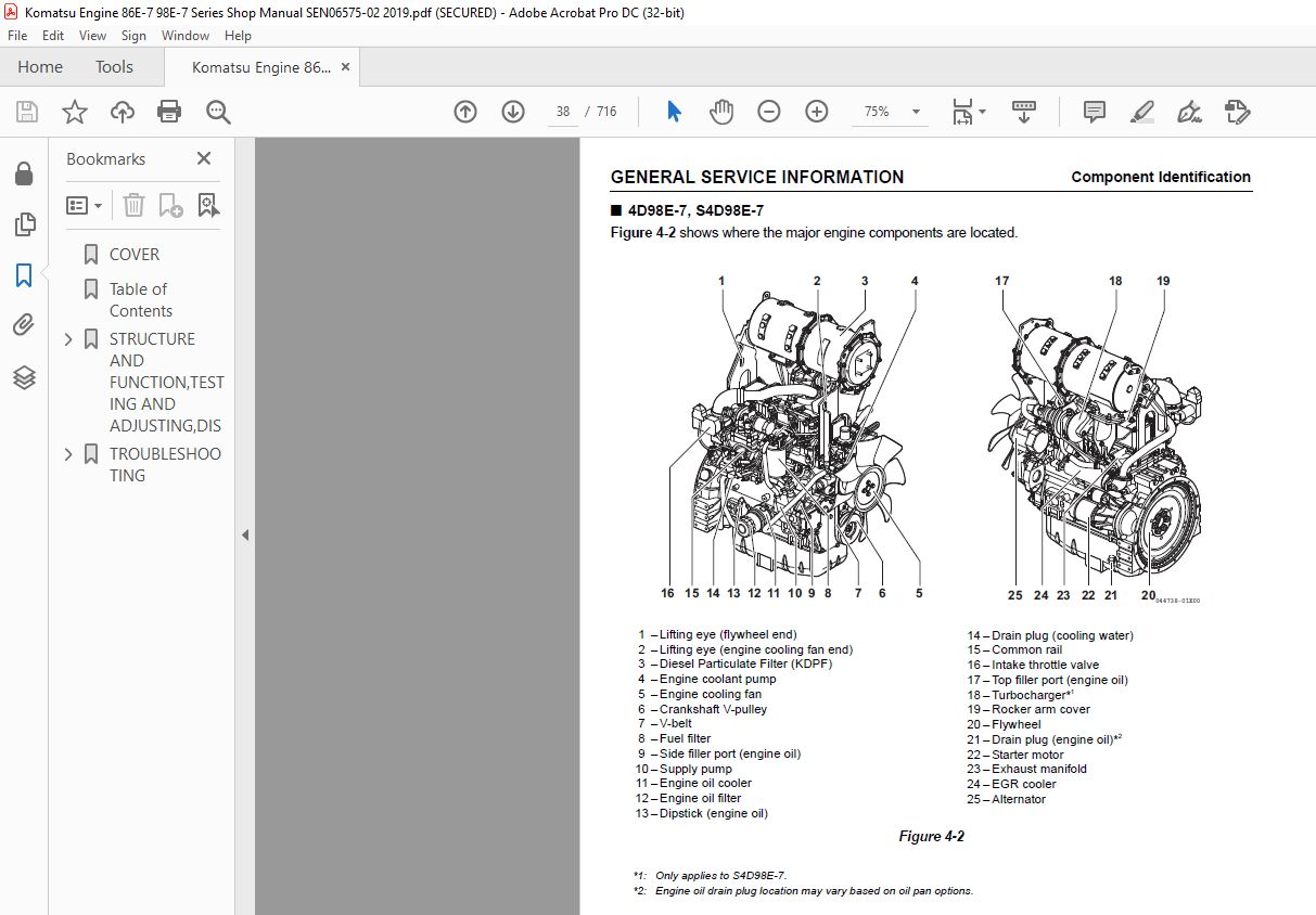
Component Identification 37
3D88E-7, S3D86E-7, 4D88E-7, S4D86E-7 37
4D98E-7, S4D98E-7 38
Function of Major Engine Components 39
Function of Cooling System Components 40
Main Electronic Control Components and Features 41
Installation Position of Sensors 43
Crank Rotation Sensor 44
Cam Speed Sensor 44
New Air Temperature Sensor 45
EGR Temperature Sensor 45
Intake Temperature Sensor 45
Fuel Temperature Sensor (equipped on supply pump) 46
Cooling Water Temperature Sensor 46
Diesel Particulate Filter (KDPF) Inside/Inlet, Exhaust Temperature Sensor 47
Rail Pressure Sensor 47
EGR Pressure Sensor 48
Diesel Particulate Filter (KDPF) Differential Pressure Sensor 49
EGR Valve 50
Intake Air Throttles 51
Acceleration Sensor (Example) 52
Diesel Fuel 53
Diesel Fuel Specifications 53
Additional technical fuel requirements 53
Precautions and concerns regarding the use of diesel fuel 53
Bio-diesel fuels 53
These B7 diesel fuels must meet certain requirements 54
Precautions and concerns regarding the use of bio-fuels: 54
Filling The Fuel Tank 54
Priming the Fuel System 55
Engine Oil 56
Engine Oil Specifications 56
Service categories 56
Definitions 56
Additional technical engine oil requirements: 56
Engine Oil Viscosity 56
Checking Engine Oil 57
Adding Engine Oil 57
Engine Oil Capacity (Typical) 57
Engine Coolant 58
Filling Radiator with Engine Coolant 59
Daily Check of the Cooling System 60
Engine Coolant Capacity (Typical) 60
Specifications 61
Description of Model Number 61
Engine General Specifications 61
Principal Engine Specifications 63
3D88E-7 63
S3D86E-7 64
4D88E-7 65
S4D86E-7 66
4D98E-7 67
S4D98E-7 68
Set Output Listed by Rotation 69
Engine Service Standards 70
Tightening Torques for Standard Bolts and Nuts 71
Abbreviations and Symbols 72
Abbreviations 72
Symbols 72
Unit Conversions 73
Unit prefixes 73
Units of length 73
Units of volume 73
Units of mass 73
Units of force 73
Units of torque 73
Units of pressure 73
Units of power 73
Units of temperature 73
Periodic Maintenance 75
Before You Begin Servicing 77
Introduction 78
The Importance of Periodic Maintenance 78
Performing Periodic Maintenance 78
Replacement Parts 78
Required EPA/ARB Maintenance USA Only 78
EPA/ARB Installation Requirements USA Only 78
Maximum exhaust gas restriction shall be: 78
Periodic Maintenance Schedule 79
Periodic Maintenance Procedures 80
Every 1000 Hours of Operation 80
Check and adjust intake/exhaust valve clearance 80
Every 1500 Hours of Operation 80
Inspect crankcase breather system 80
Every 2000 Hours of Operation 81
Lap the intake and exhaust valves 81
Every 3000 Hours of Operation 82
Inspect turbocharger (blower wash as necessary) 82
Inspect, clean and test EGR valve 82
Inspect and clean EGR lead valve 82
Check and clean of KDPF soot filter 82
Check and clean injector 82
Inspect and test intake throttle valve 82
Clean EGR cooler 83
Every 6000 Hours of Operation 83
Check and clean of KDPF soot filter 83
Engine 85
Before You Begin Servicing 87
Introduction 88
Cylinder Head Specifications 88
Adjustment Specifications 88
Cylinder Head 88
Intake/Exhaust Valve and Guide 89
Push Rod 90
Rocker Arm and Shaft 90
Valve Spring 90
Camshaft and Timing Gear Train Specifications 91
Camshaft 91
Idler Gear Shaft and Bushing 92
Timing Gear Backlash 92
Crankshaft and Piston Specifications 93
Crankshaft 93
Thrust Bearing 94
Piston 94
Piston Ring 95
Connecting Rod 98
Connecting rod small end 98
Connecting rod big end 98
Tappet 99
Cylinder Block Specifications 100
Cylinder Block 100
Special Torque Chart 101
Torque for Bolts and Nuts 101
Special Service Tools 104
Measuring Instruments 108
Cylinder Head 110
Cylinder Head Components 110
Disassembly of Cylinder Head 112
Removing the glow plugs 113
Removal of valve cover 113
Removal of rocker arm assembly 114
Disassembly of rocker arm assembly 114
Removal of cylinder head 115
Removal of intake/exhaust valves 116
Removal of valve guides 116
Cleaning of Cylinder Head Components 117
Inspection of Cylinder Head Components 117
Inspection of push rods 117
Push rod bend 117
Inspection of rocker arm assembly 118
Rocker arm shaft hole diameter 118
Rocker arm shaft outside diameter 118
Inspection of valve guides 118
Inspection of cylinder head 118
Cylinder head distortion 118
Inspection of intake and exhaust valves 119
Valve stem diameter 119
Valve stem bend 119
Valve recession 119
Valve face and valve seat 120
Inspection of valve springs 120
Fractures 120
Corrosion 120
Squareness 121
Free length 121
Reassembly of Cylinder Head 121
Reassembly of valve guides 121
Reassembly of intake and exhaust valves 122
Reassembly of cylinder head 123
Reassembly of rocker arm reassembly 123
Reassembly of the valve cover 124
Measuring and Adjusting Valve Clearance 126
3-cylinder engines 126
4-cylinder engines 126
Crankshaft and Camshaft Components 128
Disassembly of Engine 129
Disassembly of Camshaft and Timing Components 130
Removal of timing gear case cover 130
Checking timing gear backlash 130
Measuring idler gear-to-crankshaft gear backlash 131
Measuring idler gear-to-camshaft gear backlash 131
Removal of timing gears 131
Removal of oil pan 132
Removal of camshaft 132
Removal of gear case or front plate 133
Disassembly of Crankshaft and Piston Components 134
Removal of pistons 134
Removal of crankshaft 136
Inspection of Crankshaft and Camshaft Components 137
Replacement of crankshaft oil seals 138
Measure crankshaft bearing oil clearance 138
Inspection of cylinder block 138
Inspection of pistons, piston rings and wrist pin 138
Inspection of connecting rod 140
Inspection of tappets 141
Inspection of crankshaft 141
Inspection of camshaft 142
Inspection of camshaft bushing and bores 143
Inspection of idler gear and shaft 143
Inspection of flywheel 143
Honing and Boring 144
Reassembly of Crankshaft and Piston Components 145
Reassembly of pistons 145
Installation of crankshaft 147
Installation of pistons 148
Reassembly of Camshaft and Timing Components 150
Installation of gear case 150
Installation of camshaft 150
Installation of timing gears 151
Installation of gear case cover 151
Installation of oil pan 152
Final Reassembly of Engine 153
EGR System 154
EGR System (Typical Model) 154
Typical Model for Turbocharger Model 155
Disassembly of Supply Pump 156
Engine without turbocharger (3D88E-7, 4D88E-7, 4D98E-7) 158
Engine with turbocharger (S3D86E-7, S4D86E-7, S4D98E-7) 158
EGR active control 158
Cleaning the EGR Valves 159
Exit the EGR active control 159
Precautions for cleaning 159
Clean Lead Valves 160
Precautions for Installation 160
Clean EGR Cooler 160
EGR Pipe and Other Connecting Elbows 161
Installing EGR Related Components/Parts 161
Intake Throttle 162
Precautions for Handling the Intake Throttle 162
Fuel System 163
Before You Begin Servicing 165
System Structure 166
Supply pump 166
Rail 166
Injector 166
Crank rotation sensor and gear speed sensor 167
ECU 167
Fuel System Specifications 168
Torque Chart for Major Bolts and Nuts 168
Fuel System Diagram 169
Fuel System Components 170
Removal of Common Rail 171
Reassembly of Common Rail 172
Removal of Injector 173
Reassembly of injector 174
Removal of Supply Pump 175
Reassembly of Supply Pump 176
Cooling System 179
Before You Begin Servicing 181
Introduction 182
Cooling System Diagram 182
Engine Coolant Pump Components 183
Engine Coolant System Check 184
Engine Coolant Pump 184
Removal of Engine Coolant Pump 184
Disassembly of Engine Coolant Pump 185
Cleaning and Inspection 186
Temperature switch 186
Water temperature sensor 186
Thermostat 187
Radiator cap 187
Reassembly of Engine Coolant Pump 187
Installation of Engine Coolant Pump 188
Lubrication System 189
Before You Begin Servicing 191
Introduction 191
Oil Pump Service Information 192
Engine oil pressure 192
Outer rotor outside clearance 192
Outer rotor side clearance 192
Outer rotor to inner rotor tip clearance 192
Rotor shaft clearance 193
Lubrication System Diagram 194
Checking Engine Oil Pressure 195
Oil Pump Components 195
3D88E-7, S3D86E-7, 4D88E-7, S4D86E-7 195
Disassembly of Oil Pump 195
Cleaning and Inspection 196
Check outer rotor outside clearance 196
Outer rotor to inner rotor tip clearance 196
Check outer rotor side clearance 197
Check rotor shaft clearance 197
Reassembly of Oil Pump 197
4D98E-7, S4D98E-7 (Trochoid Oil Pump) 198
Disassembly of Oil Pump 198
Cleaning and Inspection 199
Check outer rotor outside clearance 199
Outer rotor to inner rotor tip clearance 199
Check outer rotor side clearance 199
Check rotor shaft clearance 200
Reassembly of Oil Pump 200
Turbocharger 201
Before You Begin Servicing 203
Introduction 204
Specifications 204
Turbocharger Service Information 204
Troubleshooting 205
Excessive exhaust smoke 205
Generates white smoke 206
Sudden oil decrease 206
Decrease in output 206
Poor (slow) response (starting) of turbocharger 206
Abnormal sound or vibration 206
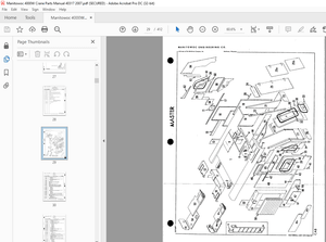
Turbocharger Components 207
Turbocharger Component Functions 208
Theory of Operation 209
Turbine 209
Compressor 209
Bearings 209
Thrust bearing 209
Radial bearing 209
Lubrication 209
Compressor Side Sealing Mechanism 209
Waste Gate Modulation 209
Waste gate control 209
Washing Procedure 210
Periodic Inspection 211
Visual Inspection 211
Inspection of Rotor Rotation 211
Inspection of Rotor Play 211
Removal of Turbocharger 211
Checking Rotor Play 212
To check rotor end play: 212
To check rotor run-out: 212
Waste Gate Valve Test 213
Waste Gate Actuator Leak Test 213
Installation of Turbocharger 213
Starter Motor 215
Before You Begin Servicing 217
Introduction 218
Starter Motor Information 218
3D88E-7 to S4D86E-7 – Standard and Optional 218
4D98E-7 and S4D98E-7 – Standard and Optional 218
Starter Motor Specifications 219
Starter Motor Troubleshooting 220
Starter Motor Components 221
Starter Motor 222
Removal of Starter Motor 222
Disassembly of Starter Motor 222
Cleaning and Inspection 224
Armature 224
Commutator surface inspection 224
Measure commutator outside diameter 224
Measure commutator insulation depth 225
Armature coil continuity test 225
Armature coil insulation test 225
Measure armature and commutator run-outs 225
Field coil 226
Field coil continuity test 226
Field coil insulation test 226
Measure brush length 226
Magnetic switch 226
Shunt coil continuity test 226
Series coil continuity test 227
Coil resistance test 227
Contact continuity test 227
Pinion clutch assembly 227
Pinion clutch assembly inspection 227
Ball bearing inspection 227
Reassembly of Starter Motor 228
Check Pinion Projection Length 229
No-Load Test 230
Installation of Starter Motor 231
Alternator 233
Before You Begin Servicing 235
Introduction 236
Dynamo and Alternator Information 236
3D88E-7 to S4D98E-7 – Standard and Optional Dynamos 236
3D88E-7 to S4D98E-7 – Standard and Optional Alternators 236
Alternator Specifications 237
Dynamo Specifications 237
Alternator Troubleshooting 238
Alternator Components 239
Alternator Wiring Diagram 240
Alternator Standard Output 241
Alternator 242
Removal of Alternator 242
Disassembly of Alternator 242
Reassembly of Alternator 244
Installation of Alternator 246
Dynamo Component Location 247
Dynamo Wiring Diagram 248
Operation of Dynamo 248
Dynamo Standard Output 249
Testing of Dynamo 250
Testing Stator Coil Continuity 250
Testing Stator Coil Short-to-Ground 250
Testing Dynamo Regulated Output 250
Dynamo 250
Removal of Dynamo 250
Disassembly of Dynamo 251
Reassembly of Dynamo 251
Installation of Dynamo 252
Electronic Control System 253
Before You Begin Servicing 255
System Structure 256
Electronic Engine Speed Control 257
Speed control 257
Engine speed curves 257
Droop control 257
Isochronous control 257
Other engine speed control 257
Low-idling speed up 257
High-idling speed down 257
Auto deceleration (optional) 258
Others 258
Diesel Particulate Filter (KDPF) 259
Outline of Diesel Particulate Filter (KDPF) 259
Overview of Diesel Particulate Filter (KDPF) regeneration control 260
Self-regeneration (passive regeneration) 260
Assisted regeneration (passive regeneration) 260
Reset regeneration (automatic regeneration) 260
Stationary regeneration (manual stationary regeneration) 260
Operation procedures of stationary regeneration 261
Precautions for stationary regeneration 261
Recovery regeneration (optional) 261
Precautions for recovery regeneration 261
KDPF service 262
Procedures for servicing the Diesel Particulate Filter (KDPF) 262
How to Remove and Reattach the Diesel Particulate Filter (KDPF) 263
How to remove the soot filter (SF) 263
KDPF flywheel housing-mounted type 263
KDPF exhaust manifold-mounted type 264
How to reattach the soot filter (SF) 266
KDPF flywheel housing-mounted type 266
KDPF exhaust manifold-mounted type 266
How to remove the KDPF unit 267
KDPF flywheel housing-mounted type 267
KDPF exhaust manifold-mounted type 268
How to reattach the KDPF 269
KDPF flywheel housing-mounted type 269
KDPF exhaust manifold-mounted type 270
SF and KDPF Maintenance Kit 272
Troubleshooting of Electronic Control System 274
Fault Detection Capability 274
SMARTASSIST DIRECT (SA-D) 276
Replacement of Components 277
Processing the KDPF regeneration after the parts replacement 277
Calculation of PM sediment amount in KDPF 278
Processing after the ECU replacement (when it is impossible to inherit from the old ECU) 278
Required processing at the CR-related parts replacement 279
Electric Wiring 281
Electric Wiring Precautions 283
Electrical Wire Resistance 284
Battery Cable Resistance 285
Electrical Wire Sizes – Voltage Drop 286
Conversion of AWG to European Standards 287
TROUBLESHOOTING 289
FAILURE CODE (DTC) GENERAL DESCRIPTION 291
Failure code (DTC) list 297
Description 304
Sensor related 305
Crank speed sensor 305
#B0336: Crank Signal Error 305
#B0337: No Crank Signal 307
Cam speed sensor 309
#B0341: Cam Signal Error 309
#B0342: No Cam Signal 311
#B1341: Cam Angle Offset Error 313
#B0008: No Signal on Both Crank and Cam Speed Sensor 315
Accelerator sensor 316
#B0123: Accelerator Sensor 1 (High voltage) 316
#B0122: Accelerator Sensor 1 (Low voltage) 318
#B0223: — 320
#B0222: — 322
#B1646: — 324
#B1647: — 326
#B0228: Accelerrator sensor 3 (Excessive sensor output) 328
#B0227: Accelerrator sensor 3 (Insufficient sensor output) 330
#B1227: — 332
#B1126: Accelerrator sensor 3 failure (Foot pedal in open position) 333
#B1125: Accelerrator sensor 3 failure (Foot pedal in closed position) 335
Intake throttle opening sensor 336
#B02E9: Intake Throttle Open Position Sens Error (High V) 336
#B02E8: Intake Throttle Open Position Sens Error (Low V) 338
EGR low pressure side sensor 340
#B0238: EGR Low Pressure Side Sensor Error (High Voltage) 340
#B0237: EGR Low Pressure Side Sensor Error (Low Voltage) 342
#B0236: EGR Low Pres Side Sens Error (Abnorm Learn Value) 344
EGR high pressure side sensor 346
#B0473: EGR High Pressure Side Sensor Error (High Voltage) 346
#B0472: EGR High Pressure Side Sensor Error (Low Voltage) 348
#B0471: EGR High Pres Side Sens Error (Abnorm Learn Value) 350
Cooling water temperature sensor 352
#B0118: Cooling Water Temperature Sens Error (High Volt) 352
#B0117: Cooling Water Temperature Sensor Error (Low Volt) 354
#B0217: — 356
New air temperature sensor 358
#B0113: New Air Temperature Sensor Error (High Voltage) 358
#B0112: New Air Temperature Sensor Error (Low Voltage) 360
Fuel temperature sensor 362
#B0183: Fuel Temperature Sensor Error (High Voltage) 362
#B0182: Fuel Temperature Sensor Error (Low Voltage) 364
#B0168: Fuel Temperature Sensor Temperature Abnormal High 366
Rail pressure sensor 368
#B0193: Rail Pressure Sensor Error (High Voltage) 368
#B0192: Rail Pressure Sensor Error (Low Voltage) 370
KDPF differential pressure sensor 372
#B2455: KDPF Differential Pressure Sens Error (High Volt) 372
#B2454: KDPF Differential Pressure Sens Error (Low Volt) 374
#B2452: KDPF Differential Pressure High Error 376
#B2453: KDPF Different Press Sens (Abnormal Learn Value) 378
KDPF high pressure side sensor 380
#B1455: KDPF High Pressure Side Sens Error (High Volt) 380
#B1454: KDPF High Pressure Side Sensor Error (Low Voltage) 382
KDPF inlet temperature sensor 384
#B1428: KDPF Inlet Temperature Sensor Error (High Voltage) 384
#B1427: KDPF Inlet Temperature Sensor Error (Low Voltage) 386
#B1436: KDPF Inlet Temperature High Error 388
KDPF intermediate temperature sensor 389
#B1434: KDPF Intermediate Temperature Sens Error (HighVolt) 389
#B1435: KDPF Intermediate Temperature Sens Error (LowVolt) 391
#B0420: KDPF Inter Temperature Low Error 393
#B1426: KDPF InterTemperature High Error (Post-injection) 394
Atmospheric pressure sensor 395
#B2229: Ambient Pressure Sensor Error (High Voltage) 395
#B2228: Ambient Pressure Sensor Error (Low Voltage) 396
#B1231: Ambient Pressure Sensor Characteristic Error 397
EGR gas temperature sensor 399
#B041D: EGR Gas Temperature Sensor Error (High Voltage) 399
#B041C: EGR Gas Temperature Sensor Error (Low Voltage) 401
Intake manifold temperature sensor 403
#B040D: Intake Manifold Temperature Sens Error (High Volt) 403
#B040C: Intake Manifold Temperature Sens Error (Low Volt) 405
Exhaust manifold temperature sensor 407
#B0546: Exhaust Manifold Temperature Sens Error (HighVolt) 407
#B0545: Exhaust Manifold Temperature Sens Error (Low Volt) 409
Contact output related 411
Main relay 411
#B068B: Main Relay Contact Stuck 411
#B068A: Main Relay Early Opening 413
Startup assist relay 415
#B0543: Startup Assist Relay Open Circuit 415
#B0541: Startup Assist Relay GND Short Circuit 417
CRS (common rail system) related 419
Injector 4 419
#B0204 (4-cylinder engine): Injector of 4th Cylinder OpenC (Inherent Location) #B0203 (3-cylinder engine): — 419
#B0271 (4-cylinder engine): Injector of 4th Cylinder Coil Short Circuit #B0268 (3-cylinder engine): — 421
#B1271 (4-cylinder engine): Injector of 4th Cylinder Short Circuit #B1268 (3-cylinder engine): — 423
Injector 2 425
#B0202: Injector of 2nd Cylinder OpenC (Inherent Location) 425
#B0265: Injector of 2nd Cylinder Coil Short Circuit 427
#B1265: Injector of 2nd Cylinder Short Circuit 429
Injector 1 431
#B0201: Injector of 1st Cylinder OpenC (Inherent Location) 431
#B0262: Injector of 1st Cylinder Coil Short Circuit 433
#B1262: Injector of 1st Cylinder Short Circuit 435
Injector 3 437
#B0203 (4-cylinder engine): Injector of 3rd Cylinder OpenC (Inherent Location) 437
#B0268 (4-cylinder engine): Injector of 3rd Cylinder Coil Short Circuit 439
#B1268 (4-cylinder engine): Injector of 3rd Cylinder Short Circuit 441
Injector (common) 443
#B0611: Injector Drive IC Error 443
#B1146: Injector Drive Circuit (Bank1) Short Circuit 444
#B1149: Injector Drive Circuit (Bank2) Short Circuit 446
#B1648: Injector of 1st Cylinder Compensation Value Error 448
#B1649: Injector of 2nd Cylinder Compensation Value Error 449
#B1650: Injector of 3rd Cylinder Compensation Value Error 450
#B1651: Injector of 4th Cylinder Compensation Value Error 451
SCV (MPROP) 452
#B1641: SCV (MPROP) (Low Side VB Short) 452
#B1643: SCV (MPROP) (Low Side GND Short) 453
#B0629: SCV (MPROP) (High Side VB Short) 455
#B1642: SCV (MPROP) (High Side GND Short) 457
#B0627: SCV (MPROP) (Open Circuit) 458
#B062A: SCV (MPROP) (Drive Current High Error) 459
#B1645: SCV (MPROP) (Pump Overload Error) 461
Abnormal rail pressure 463
#B0088: Actual Rail Pressure Rise Error 463
#B0094: Rail Press Deviation Error in Act Rail Press Drop 465
#B0093: Rail Press Deviation Error in Act Rail Press Rise 467
PLV (Common rail pressure limit valve) 469
#B000F: PLV Open Valve 469
#B1666: PLV (Number of times of PLV Valve Opening Error) 471
#B1667: PLV (Time of PLV Valve Opening Error) 473
#B1668: PLV (Non-Performance) 475
#B1665: PLV (Malfunction) 477
Rail pressure control 479
#B1669: Rail Press Control (Fuel Temp High in PLV V Open) 479
#B1670: Rail Press Control (Pump or Fuel Temp Error) 481
Actuator 482
Intake throttle drive circuit 482
#B0660: No-load of Throttle Valve Drive H Bridge Circuit 482
#B1658: Power Short of Throttle Valve Drive H Bridge Out 1 483
#B1659: GND Short of Throttle Valve Drive H Bridge Out 1 484
#B1660: O-load on the Drive H Bridge Cir of Throttle Valve 485
#B1661: VB P Short of Throttle Valve Drive H Bridge Out 2 486
#B1662: GND Short of Throttle Valve Drive H Bridge Out 2 487
EGR 488
#B0404: EGR Voltage High Error 488
#B1404: EGR Voltage Low Error 489
#B1409: EGR Feedback Error 490
#BG401: EGR ECM Data Error 491
#B0403: Open Circuit Between the EGR Motor Coils 492
#B1405: Short Circuit Between the EGR Motor Coils 493
#B0488: EGR Position Sensor Error 494
#B148A: EGR Stuck Open Valve Error 495
#B049D: EGR Initialization Error 496
#BH401: EGR Target Value Out of Range 497
#B1410: EGR High Temperature Thermistor Error 498
#B1411: EGR Low Temperature Thermistor Error 499
Exhaust throttle 500
#B1438: Exhaust throttle (Voltage fault) 500
#B1439: Exhaust throttle (Motor fault) 501
#B1440: Exhaust throttle (Sensor system fault) 502
#B1441: Exhaust throttle (MPU fault) 503
#B1442: Exhaust throttle (PCB fault) 504
#B1443: Exhaust throttle (CAN fault) 505
Communication related 506
CAN1 506
#BG10B: CAN1 (for EGR): Reception Time Out 506
#BH107: Exhaust throttle (CAN message from the exhaust throttle time out) 507
CAN2 508
#BG292: TSC1 (CAN Message) Reception Time Out (SA1) 508
#BH301: TSC1 (CAN Message) Reception Time Out (SA2) 510
#BH292: Y_ECR1 (CAN Message) Reception Time Out 512
#BH293: Y_EC (CAN Message) Reception Time Out 514
#BH294: — 516
#BH296: — 518
#BH298: — 520
#BG168: — 522
#BK002: — 524
#BH300: — 526
#BH302: — 528
#BH303: Y_DPFIF (CAN Message) Reception Time Out 530
ECU related 532
EEPROM 532
#B0601: EEPROM Memory Deletion Error 532
#B160E: EEPROM Memory Read Error 533
#B160F: EEPROM Memory Writing Error 534
ECU internal fault 535
#B1613: CY146 SPI Communication Error 535
#B1608: Excessive Voltage of Supply 1 536
#B1617: Insufficient Voltage of Supply 1 537
#B1609: Sensor Supply Voltage Error 1 538
#B1618: Sensor Supply Voltage Error 2 539
#B1619: Sensor Supply Voltage Error 3 540
#B1626: Actuator Drive Circuit 1 Short to Ground 541
#B1633: Actuator Drive Circuit 2 Short to Ground 542
#B1467: Actuator Drive Circuit 3 Short to Ground 543
#B1469: AD Converter Error 1 544
#B1470: AD Converter Error 2 545
#B1471: External Monitoring IC and CPU Error 1 546
#B1472: External Monitoring IC and CPU Error 2 547
#B1473: ROM Error 548
#B1474: Shutoff Path Error 1 549
#B1475: Shutoff Path Error 2 550
#B1476: Shutoff Path Error 3 551
#B1477: Shutoff Path Error 4 552
#B1478: Shutoff Path Error 5 553
#B1479: Shutoff Path Error 6 554
#B1480: Shutoff Path Error 7 555
#B1481: Shutoff Path Error 8 556
#B1482: Shutoff Path Error 9 557
#B1483: Shutoff Path Error 10 558
#B1484: Recognition Error of Engine Speed 559
Contact input related 560
Air cleaner switch 560
#B1101: — 560
Oil/water separator switch 562
#B1151: — 562
Charge switch 564
#B1562: Charge Switch Open Circuit 564
#B1568: Charge Alarm 566
Oil pressure switch 568
#B1192: Oil Pressure Switch Open Circuit 568
#B1198: Oil Pressure Low Error Alarm 570
Post treatment control 572
KDPF 572
#B2463: Overaccumulation (Method C) 572
#B1463: Overaccumulation (Method P) 573
#B2458: Defective Regeneration (StationaryRegene Failure) 574
#B2459: Defective Regeneration (StationaryR Not Performed) 575
KDPF OP interface 576
#B242F: Ash Cleaning Request 1 576
#B1420: Ash Cleaning Request 2 577
#B1421: Stationary Regeneration Standby 578
#B1424: Backup Mode 579
#B1425: — 580
#B1445: — 581
#B1446: — 582
Others 583
Overspeed 583
#B0219: Overspeed 583
Immobilizer 584
#BG167: Immobilizer CAN Communication Error 584
#BG426: Immobilizer System Error 586
METHOD AND PROCEDURE OF FAILURE DIAGNOSIS 587
Description 589
E-ECU pin layout diagram 590
How to use the Tier 4 checker harness 592
Sensor related 593
Crank speed sensor 593
Cam speed sensor 596
Accelerator sensor 600
Intake throttle position sensor 604
EGR low pressure side sensor 607
EGR high pressure side sensor 610
Cooling water temperature sensor 613
New air temperature sensor 617
Fuel temperature sensor 621
Rail pressure sensor 625
KDPF differential pressure sensor 628
KDPF inlet temperature sensor 632
KDPF intermediate temperature sensor 636
EGR gas temperature sensor 640
Intake manifold temperature sensor 644
Exhaust manifold temperature sensor 648
Contact output related 652
Main relay 652
Startup assist relay (Glow relay) 656
Contact input related 660
Contact input related 1 660
Contact input related 2 664
CRS (common rail system) related 667
Injector 667
Injector open circuit and coil short circuit 667
Injector short circuit 671
High-pressure pump (MPROP) 673
Actuator 676
Intake throttle drive circuit 676
EGR valve 681
EGR valve 685
Communication related 687
CAN1 687
CAN2 690
ECU related 693
Others 696
Overspeed 696
Immobilizer 698
MECHANICAL SYSTEM FAILURE DIAGNOSIS 701
Special Service Tools 703
Tier 4 (BOSCH) Compression Inspection Procedures 704
Standard compression pressure (reference value) 705
Engine speed and compression pressure (use for reference) 705
Measured Value and Troubleshooting 706
Quick Reference Table for Troubleshooting 706
Failure Diagnostic List 707
DESCRIPTION:
Komatsu 86E-7 – 98E-7 Series Engine (With common rail injection system) Shop Manual SEN06575-02 – PDF DOWNLOAD
INTRODUCTION:
How to read the shop manual:
• Some of the attachments and options described in this shop manual may not be available in some areas.
If they are required, consult your Komatsu distributor.
• The materials and specifications are subject to change without notice.
• Shop Manuals are available for “machine part” and “engine part”. For the engine unit, see the shop
manual for the machine which has the same engine model.
• Actual machine may differ from the images which are contained in this manual. A typical model is shown
in the illustrations of this shop manual.
Composition of the shop manual:
This shop manual contains technical information necessary to perform services in workshops. It is divided
into “Structure and Function, Testing and Adjusting, Disassembly and Assembly, and Maintenance
Standard” and “Troubleshooting” section for the ease of use.
Basic informaton:
This Shop Manual describes the service procedures for 86E – 98E-7 series engines have common rail
injection system.
Please use this manual for accurate, quick and safe servicing of the engine. Since the directions in this
manual are for a typical engine, some specifications and components may be different from your engine.
For the replacement of some parts and troubleshooting for this series engines, the Diagnostics Tool called
SMARTASSIST-Direct is required. In addition, please read both “Troubleshooting” Section and
SMARTASSIST-Direct Operation Manual.
IMAGES PREVIEW OF THE MANUAL:
More products