$38
Komatsu 8V170-1 Series Engine Shop Manual SEBE61700104 – PDF DOWNLOAD
Komatsu 8V170-1 Series Engine Shop Manual SEBE61700104 – PDF DOWNLOAD
FILE DETAILS:
Komatsu 8V170-1 Series Engine Shop Manual SEBE61700104 – PDF DOWNLOAD
Language : English
Pages : 346
Downloadable : Yes
File Type : PDF
Size: 46 MB
IMAGES PREVIEW OF THE MANUAL:
DESCRIPTION:
Komatsu 8V170-1 Series Engine Shop Manual SEBE61700104 – PDF DOWNLOAD
GENERAL PRECAUTIONS:
Mistakes in operation are extremely dangerous. Read the Operation and Maintenance Manual carefully BEFORE operating the machine.1 .Before carrying out any greasing or repairs, read all the precautions given on the decals which are fixed to the machine.
2.When carrying out any operation, always wear safety shoes and helmet. Do not wear loose work clothes, or clothes with buttons missing.
- Always wear safety glasses when hitting parts with a hammer.
- Always wear safety glasses when grinding parts with a grinder, etc.
3. If welding repairs are needed, always have a trained, experienced welder carry out the work. When carrying out welding work, always wear welding gloves, apron, glasses, cap and other clothes suited for welding work.4.When carrying out any operation with two or more workers, always agree on the op- erating procedure before starting. Always inform your fellow workers before starting any step of the operation. Before starting work, hang UNDER REPAIR signs on the controls in the operator’s compartment.5. Keep all tools in good condition and learn the correct way to use them.
6. Decide a place in the repair workshop to keep tools and removed parts. Always keep the tools and parts in their correct places. Always keep the work area clean and make sure that there is no dirt or oil on the floor. Smoke only in the areas provided for smoking. Never smoke while working.PREPARATIONS FOR WORK:
7. Before adding or making any repairs, park the machine on hard, level ground, and block the wheels to
prevent the machine from moving.
8. Before starting work, lower outrigger, bucket or any other work equipment to the ground. If this is not possible,
use blocks to prevent the work equipment from falling down. In addition, be sure to lock all the control levers and hang warning sign on them.
9. When disassembling or assembling, support the machine with blocks, jacks or stands before starting
work.
10. Remove all mud and oil from the steps or other places used to get on and off the machine. Always use the handrails, ladders or steps when getting on or off the machine.Never jump on or off the machine. If it is impossible to use the handrails, ladders or steps, use a stand to provide safe footing.
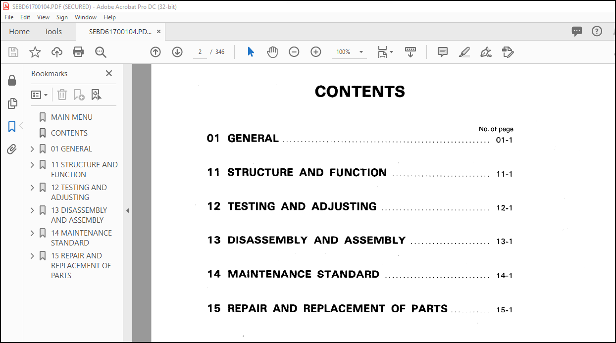
TABLE OF CONTENTS:
Komatsu 8V170-1 Series Engine Shop Manual SEBE61700104 – PDF DOWNLOAD
MAIN MENU………………………………………………………………………… 0
CONTENTS…………………………………………………………………………. 2
01 GENERAL……………………………………………………………………….. 13
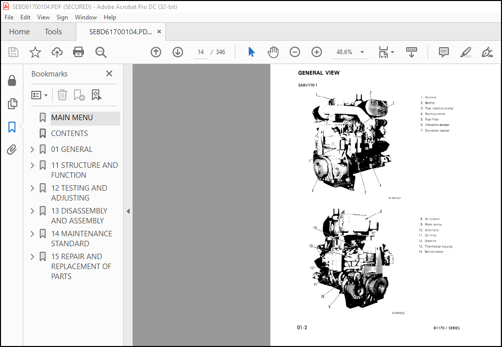
GENERAL VIEW …………………………………………………………………. 14
SPECIFICATIONS ……………………………………………………………….. 15
GENERAL ASSEMBLY DRAWING ………………………………………………………. 16
WEIGHT TABLE …………………………………………………………………. 28
ENGINE PERFORMANCE CURVE ………………………………………………………. 29
11 STRUCTURE AND FUNCTION………………………………………………………….. 33
GENERAL STRUCTURE……………………………………………………………… 34
INTAKE AND EXHAUST SYSTEM………………………………………………………. 36
INTAKE SYSTEM …………………………………………………………….. 36
EXHAUST SYSTEM ……………………………………………………………. 37
TURBOCHARGER ……………………………………………………………… 38
ENGINE BODY…………………………………………………………………… 40
CYLINDER HEAD …………………………………………………………….. 40
VALVE SYSTEM ……………………………………………………………… 42
CYLINDER BLOCK ……………………………………………………………. 44
MAIN REVOLVING SYSTEM ……………………………………………………… 45
TIMING GEAR ………………………………………………………………. 46
FLYWHEEL AND FLYWHEEL HOUSING ………………………………………………. 48
LUBRICATION SYSTEM…………………………………………………………….. 49
LUBRICATION SYSTEM CHART …………………………………………………… 49
OIL PUMP …………………………………………………………………. 50
OIL FILTER AND SAFETY VALVE ………………………………………………… 51
OIL COOLER ……………………………………………………………….. 52
OIL COOLER BYPASS VALVE ……………………………………………………. 53
PISTON COOLING VALVE……………………………………………………….. 53
MECHANICAL PUMP……………………………………………………………. 54
FUEL SYSTEM…………………………………………………………………… 55
FUEL SYSTEM CHART …………………………………………………………. 55
FUEL INJECTION PUMP ……………………………………………………….. 56
FUEL INJECTION NOZZLE ……………………………………………………… 71
FEED PUMP ………………………………………………………………… 72
FUEL INJECTION PUMP DRIVE ………………………………………………….. 75
TIMER…………………………………………………………………….. 76
FUEL FILTER ………………………………………………………………. 79
STARTING AID………………………………………………………………. 80
ENGINE STOP MOTOR …………………………………………………………. 81
COOLING SYSTEM………………………………………………………………… 87
COOLING SYSTEM CHART ………………………………………………………. 87
WATER PUMP ……………………………………………………………….. 88
WATER PUMP DRIVE ………………………………………………………….. 89
FAN DRIVE AND TENSION PULLEY ……………………………………………….. 90
CORROSION RESISTOR ………………………………………………………… 91
THERMOSTAT ……………………………………………………………….. 92
ACCESSORY…………………………………………………………………….. 93
AIR COMPRESSOR MOUNTING ……………………………………………………. 93
AIR COMPRESSOR ……………………………………………………………. 94
ALTERNATOR WITH REGULATOR ………………………………………………….. 95
STARTING MOTOR ……………………………………………………………. 96
12 TESTING AND ADJUSTING…………………………………………………………… 97
COOLING SYSTEM………………………………………………………………… 98
CHECKING AND ADJUSTING ALTERNATOR BELT TENSION ……………………………….. 98
ENGINE BODY……………………………………………………………………100
ADJUSTING VALVE CLEARANCE …………………………………………………..100
FUEL SYSTEM …………………………………………………………………..101
TESTING AND ADJUSTING FUEL INJECTION TIMING …………………………………..101
ADJUSTING FUEL INJECTION TIMING BY DELIVERY CHECK ……………………………..102
ADJUSTING FUEL INJECTION NOZZLE CRACKING PRESSURE ……………………………..103
ADJUSTING ENGINE STOP MOTOR CABLE ……………………………………………105
FUEL INJECTION PUMP CALIBRATION DATA …………………………………………107
PERFORMANCE TEST ……………………………………………………………..111
RUN-IN STANDARD ……………………………………………………………111
PERFORMANCE TEST CRITERIA …………………………………………………..112
TESTING AND ADJUSTING TOOL LIST ……………………………………………..114
TESTING AND ADJUSTING DATA ………………………………………………….116
TROUBLESHOOTING…………………………………………………………….119
POINTS TO REMEMBER WHEN TROUBLESHOOTING …………………………………..121
METHOD OF USING TROUBLESHOOTING CHART …………………………………….122
S-1 Starting performance is poor (Starting always takes time)………………..126
S-2 Engine does not start ……………………………………………….127
1. Engine does not turn ……………………………………………..127
2. Engine turns but no exhaust comes out (Fuel is not being injected) ……128
3. Exhaust gas comes out but engine does not start (Fuel is ……………..129
S-3 Engine does not pick up smoothly (Follow-up is poor) ……………………130
S-4 Engine stops during operations ……………………………………….131
S-5 Engine does not rotate smoothly (hunting) ……………………………..132
S-6 Engine lacks output (no power) ……………………………………….133
S-7 Exhaust gas is black (incomplete combustion) …………………………..134
S-8 Oil consumption is excessive (or exhaust gas is blue) …………………..135
S-9 Oil becomes contaminated quickly ……………………………………..136
S-10 Fuel consumption is excessive ……………………………………….137
S-11 Oil is in cooling water, or water spurts back, or water level goes down ….138
S-12 Oil pressure lamp lights up (drop in oil pressure) …………………….139
S-13 Oil level rises …………………………………………………..140
S-14 Water temperature becomes too high (overheating) ………………………141
S-15 Abnormal noise is made ……………………………………………..142
S-16 Vibration is excessive ……………………………………………..143
13 DISASSEMBLY AND ASSEMBLY…………………………………………………………145
GENERAL……………………………………………………………………….148
DISASSEMBLY………………………………………………………………..148
WASHING……………………………………………………………………187
WASHING CYLINDER BLOCK…………………………………………………..189
WASHING CRANKSHAFT………………………………………………………190
MEASURING AND INSPECTING PARTS……………………………………………….191
MEASURING PARTS…………………………………………………………192
MEASURING CURVATURE OF CRANKSHAFT…………………………………………192
MEASURING OUTSIDE DIAMETER OF JOURNAL……………………………………..192
MEASURING DEPTH OF CYLINDER LINER COUNTERBORE………………………………193
MEASURING MAIN BEARING BORE………………………………………………193
MEASURING CURVATURE OF CAMSHAFT…………………………………………..194
MEASURING OUTSIDE DIAMETER OF JOURNAL……………………………………..194
MEASURING HEIGHT OF CAM………………………………………………….194
MEASURING PISTON RING GROOVE……………………………………………..195
MEASURING PISTON RING END GAP…………………………………………….195
ASSEMBLY…………………………………………………………………..199
14 MAINTENANCE STANDARD…………………………………………………………….275
INTAKE AND EXHAUST SYSTEM ………………………………………………………276
TURBOCHARGER ………………………………………………………………276
ENGINE BODY……………………………………………………………………277
CYLINDER HEAD ……………………………………………………………..277
VALVE AND VALVE GUIDE ………………………………………………………278
ROCKER ARM SHAFT …………………………………………………………..279
CROSSHEAD …………………………………………………………………280
CAM FOLLOWER AND PUSH ROD …………………………………………………..281
CYLINDER BLOCK …………………………………………………………….282
CYLINDER LINER …………………………………………………………….284
CAMSHAFT…………………………………………………………………..285
CRANKSHAFT ………………………………………………………………..286
PISTON ……………………………………………………………………288
CONNECTING ROD …………………………………………………………….289
TIMING GEAR ……………………………………………………………….290
FLYWHEEL AND FLYWHEEL HOUSING ……………………………………………….292
LUBRICATION SYSTEM……………………………………………………………..293
OIL PUMP ………………………………………………………………….293
MAIN RELIEF VALVE, PISTON COOLING VALVE AND OIL COOLER BYPASS VALVE ……………294
COOLING SYSTEM ………………………………………………………………..295
WATER PUMP ………………………………………………………………..295
15 REPAIR AND REPLACEMENT OF PARTS ………………………………………………….297
CYLINDER HEAD …………………………………………………………………298
TESTING AND INSPECTING …………………………………………………………299
REPAIRING MOUNTING FACE OF CYLINDER HEAD BY GRINDING ………………………………301
REPLACING VALVE SEAT INSERTS ……………………………………………………302
REPLACING NOZZLE HOLDER SLEEVE ………………………………………………….307
REPLACING VALVE GUIDE ………………………………………………………….311
REPLACING CROSS HEAD GUIDE ……………………………………………………..312
GRINDING THE VALVE …………………………………………………………….313
CYLINDER BLOCK ………………………………………………………………..314
TESTING AND INSPECTING …………………………………………………………315
GRINDING THE TOP SURFACE OF CYLINDER BLOCK ……………………………………….317
REPLACING MAIN METAL CAP ……………………………………………………….322
REPLACING CAM BUSHING ………………………………………………………….324
CRANKSHAFT ……………………………………………………………………325
REPAIRING THE CRANKSHAFT ……………………………………………………….332
CONNECTING ROD ………………………………………………………………..340
REPLACING CAM GEAR……………………………………………………………..344
REPLACING FLYWHEEL RING GEAR ……………………………………………………344
More products