$38
Komatsu 95 Series Diesel Engine Shop Manual SEBE61460114 – PDF DOWNLOAD
Komatsu 95 Series Diesel Engine Shop Manual SEBE61460114 – PDF DOWNLOAD
FILE DETAILS:
Komatsu 95 Series Diesel Engine Shop Manual SEBE61460114 – PDF DOWNLOAD
Language : English
Pages : 820
Downloadable : Yes
File Type : PDF
Size: 55.8 MB
IMAGES PREVIEW OF THE MANUAL:
DESCRIPTION:
Komatsu 95 Series Diesel Engine Shop Manual SEBE61460114 – PDF DOWNLOAD
FOREWORD:
GENERAL:
- This shop manual has been prepared as an aid to improve the quality of repairs by giving the
serviceman an accurate understanding of the product and by showing him the correct way to perform
repairs and make judgements. Make sure you understand the contents of this manual and use it to full
effect at every opportunity. - This shop manual mainly contains the necessary technical information for operations performed in a
service workshop. For ease of understanding, the manual is divided into the following chapters; these
chapters are further divided into the each main group of components.
STRUCTURE AND FUNCTION
This section explains the structure and function of each component. It serves not only to give
an understanding of the structure, but also serves as reference material for troubleshooting.
TESTING AND ADJUSTING
This section explains checks to be made before and after performing repairs, as well as
adjustments to be made at completion of the checks and repairs.
Troubleshooting charts correlating “Problems” to “Causes” are also included in this section.
DISASSEMBLY AND ASSEMBLY
This section explains the order to be followed when removing, installing, disassembling or
assembling each component, as well as precautions to be taken for these operations.
MAINTENANCE STANDARD
This section gives the judgement standards when inspecting disassembled parts
TABLE OF CONTENTS:
Komatsu 95 Series Diesel Engine Shop Manual SEBE61460114 – PDF DOWNLOAD
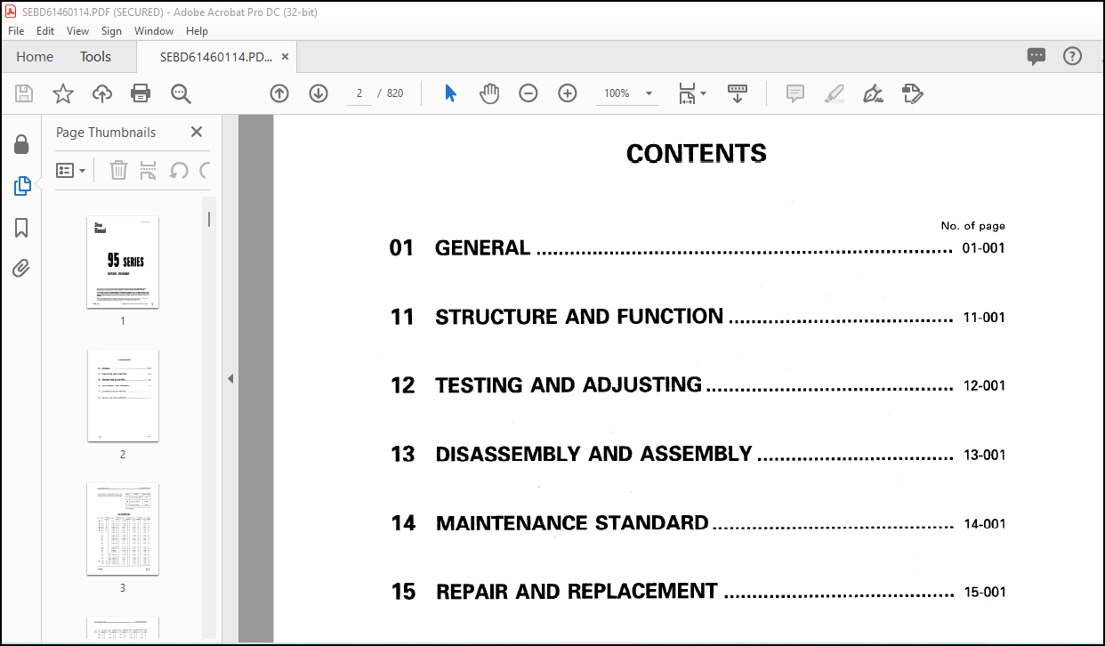
MAIN MENU……………………………………………………………………………………….. 0
CONTENTS………………………………………………………………………………………… 2
01 GENERAL ……………………………………………………………………………………… 27
GENERAL VIEW ………………………………………………………………………………… 28
SPECIFICATIONS ………………………………………………………………………………. 30
GENERAL ASSEMBLY DRAWING ……………………………………………………………………… 52
ENGINE PERFORMANCE CURVE ……………………………………………………………………… 94
WEIGHT TABLE………………………………………………………………………………….154
11 STRUCTURE AND FUNCTION …………………………………………………………………………157
GENERAL STRUCTURE …………………………………………………………………………….158
INTAKE AND EXHAUST SYSTEM ……………………………………………………………………..169
INTAKE AND EXHAUST SYSTEM…………………………………………………………………..169
FTG AIR CLEANER……………………………………………………………………………185
TURBOCHARGER………………………………………………………………………………189
AFTER-COOLER………………………………………………………………………………196
ENGINE BODY…………………………………………………………………………………..198
CYLINDER HEAD……………………………………………………………………………..198
VALVE SYSTEM………………………………………………………………………………218
CYLINDER BLOCK…………………………………………………………………………….226
CYLINDER LINER…………………………………………………………………………….232
MAIN CIRCULATION SYSTEM…………………………………………………………………….234
TIMING GEAR……………………………………………………………………………….252
FLYWHEEL AND FLYWHEEL HOUSING……………………………………………………………….258
LUBRICATION SYSTEM…………………………………………………………………………….263
LUBRICATION SYSTEM CHART……………………………………………………………………263
OIL PUMP …………………………………………………………………………………269
OIL FILTER ……………………………………………………………………………….270
OIL COOLER ……………………………………………………………………………….272
FUEL SYSTEM ………………………………………………………………………………….274
FUEL SYSTEM CHART …………………………………………………………………………274
FUEL INJECTION PUMP ……………………………………………………………………….286
GOVERNOR………………………………………………………………………………….316
FEED PUMP…………………………………………………………………………………320
FUEL INJECTION NOZZLE ……………………………………………………………………..322
FUEL CUT SOLENOID …………………………………………………………………………325
ENGINE STOP MOTOR …………………………………………………………………………328
FUEL FILTER ………………………………………………………………………………333
WATER SEPARATOR …………………………………………………………………………..334
COOLING SYSTEM ……………………………………………………………………………….335
COOLING SYSTEM CHART ………………………………………………………………………335
WATER PUMP ……………………………………………………………………………….338
CORROSION RESISTOR (OPTION) ………………………………………………………………..341
THERMOSTAT AND FAN DRIVE ………………………………………………………………….342
ELECTRICAL SYSTEM……………………………………………………………………………..352
ALTERNATOR………………………………………………………………………………..352
STARTING MOTOR ……………………………………………………………………………361
ELECTRICAL INTAKE AIR HEATER ……………………………………………………………….367
ACCESSORY…………………………………………………………………………………….372
AIR COMPRESSOR…………………………………………………………………………….372
12 TESTING AND ADJUSTING…………………………………………………………………………..375
INTAKE AND EXHAUST SYSTEM………………………………………………………………………376
ADJUSTING VALVE CLEARANCE…………………………………………………………………..376
MEASURING EXHAUST GAS COLOR…………………………………………………………………378
ENGINE BODY…………………………………………………………………………………..379
MEASURING COMPRESSION PRESSURE………………………………………………………………379
MEASURING BLOW-BY PRESSURE………………………………………………………………….380
ADJUSTING ENGINE SPEED SENSOR……………………………………………………………….381
FUEL SYSTEM…………………………………………………………………………………..382
CHECKING AND ADJUSTING FUEL INJECTION TIMING………………………………………………….382
ADJUSTING GOVERNOR…………………………………………………………………………392
TESTING AND ADJUSTING FUEL CUT SOLENOID………………………………………………………395
PROCEDURE FOR ADJUSTING ENGINE STOP MOTOR CABLE……………………………………………….400
ADJUSTING FUEL INJECTION PRESSURE……………………………………………………………402
LUBRICATION SYSTEM…………………………………………………………………………….405
MEASURING OIL PRESSURE……………………………………………………………………..405
MEASURING OIL TEMPERATURE…………………………………………………………………..406
COOLING SYSTEM………………………………………………………………………………..407
MEASURING WATER TEMPERATURE…………………………………………………………………407
TESTING AND ADJUSTING FAN BELT TENSION……………………………………………………….408
FUEL INJECTION PUMP CALIBRATION DATA…………………………………………………………….409
PERFORMANCE TEST………………………………………………………………………………528
RUN-IN STANDARD……………………………………………………………………………528
PERFORMANCE TEST CRITERIA…………………………………………………………………..537
TESTING AND ADJUSTING TOOL LIST……………………………………………………………..558
TESTING AND ADJUSTING DATA………………………………………………………………….559
TROUBLESHOOTING……………………………………………………………………………….582
METHOD OF USING TROUBLESHOOTING TABLE………………………………………………………..583
POINTS TO REMEMBER WHEN TROUBLESHOOTING………………………………………………………587
S-1 Starting performance is poor (Starting always takes time) ………………………………….588
S-2 Engine does not start…………………………………………………………………..589
(1) Engine does not turn………………………………………………………………..589
(2) Engine turns but no exhaust gas comes out (Fuel is not being injected)……………………590
(3) Exhaust gas comes out but engine does not start (Fuel is being injected)………………….591
S-3 Engine does not pick up smoothly (Follow-up is poor) ………………………………………592
S-4 Engine stops during operations ………………………………………………………….593
S-5 Engine does not rotate smoothly …………………………………………………………594
S-6 Engine lacks output (no power) ………………………………………………………….595
S-7 Exhaust gas is black (incomplete combustion) ……………………………………………..596
S-8 Oil consumption is excessive (or exhaust gas is blue)………………………………………597
S-9 Oil becomes contaminated quickly ………………………………………………………..598
S-10 Fuel consumption is excessive ………………………………………………………….599
S-11 Oil is in cooling water, or water spurts back, or water level ……………………………..600
S-12 Oil pressure lamp lights up (drop in oil pressure) ……………………………………….601
S-13 Oil level rises……………………………………………………………………….602
S-14 Water temperature becomes too high (overheating) …………………………………………603
S-15 Abnormal noise is made…………………………………………………………………604
S-16 Vibration is excessive…………………………………………………………………605
S-17 Diagnosis of electronical governor by diagnosis display (electronical governor made by ZEXEL)….606
13 DISASSEMBLY AND ASSEMBLY………………………………………………………………………..622
3D95S-W-1…………………………………………………………………………………….623
GENERAL DISASSEMBLY………………………………………………………………………..624
GENERAL ASSEMBLY ………………………………………………………………………….631
4D95S-1………………………………………………………………………………………644
GENERAL DISASSEMBLY………………………………………………………………………..645
GENERAL ASSEMBLY ………………………………………………………………………….655
4D95L SERIES………………………………………………………………………………….671
GENERAL DISASSEMBLY………………………………………………………………………..671
GENERAL ASSEMBLY…………………………………………………………………………..685
6D95L SERIES………………………………………………………………………………….707
GENERAL DISASSEMBLY………………………………………………………………………..707
GENERAL ASSEMBLY…………………………………………………………………………..721
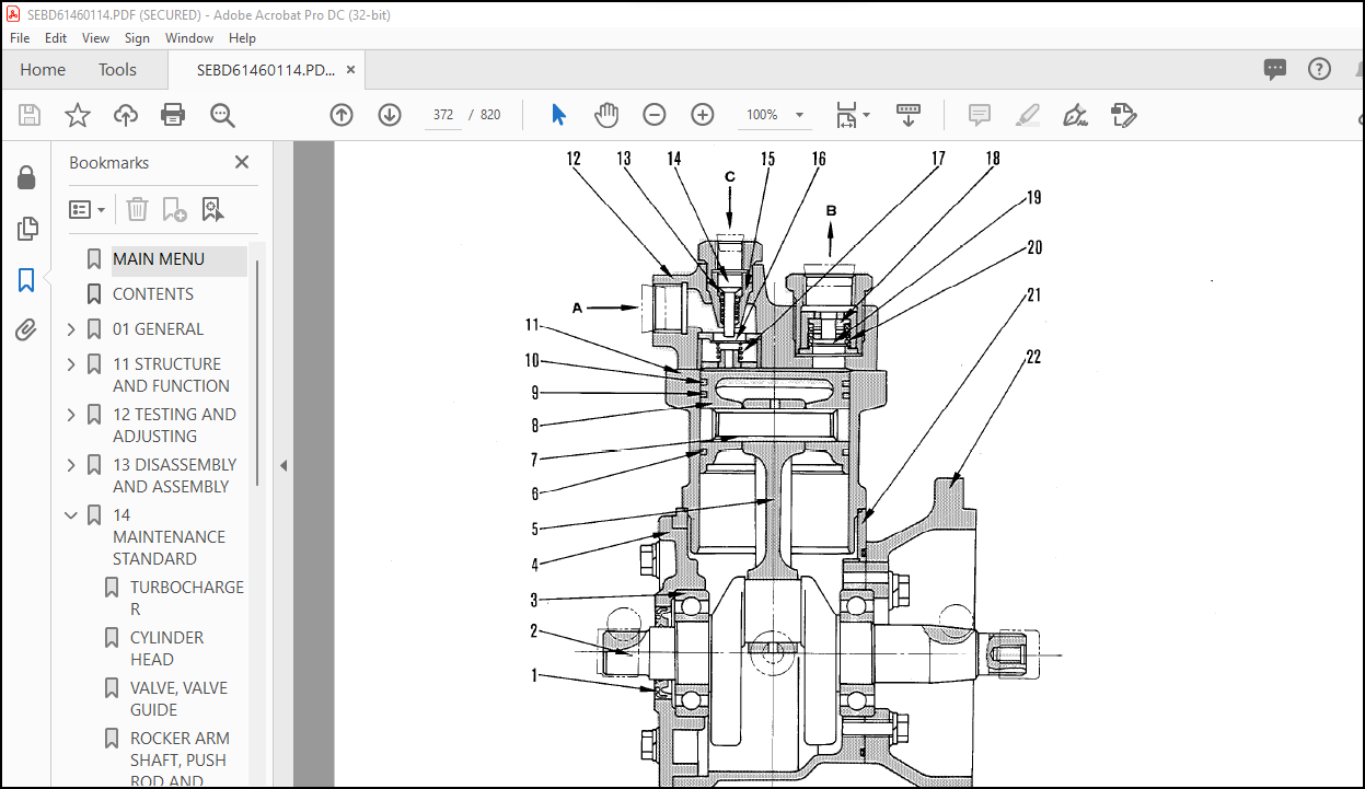
DISASSEMBLY AND ASSEMBLY OF AIR COMPRESSOR……………………………………………………….745
14 MAINTENANCE STANDARD …………………………………………………………………………..752
TURBOCHARGER …………………………………………………………………………………753
CYLINDER HEAD ………………………………………………………………………………..756
VALVE, VALVE GUIDE…………………………………………………………………………….761
ROCKER ARM SHAFT, PUSH ROD AND TAPPET……………………………………………………………764
CYLINDER BLOCK ……………………………………………………………………………….765
CRANKSHAFT …………………………………………………………………………………..767
CAMSHAFT …………………………………………………………………………………….771
TIMING GEAR (HELICAL GEAR) …………………………………………………………………….777
FLYWHEEL AND FLYWHEEL HOUSING ………………………………………………………………….782
PISTON, PISTON RING AND PISTON PIN………………………………………………………………783
CONNECTING ROD ……………………………………………………………………………….792
OIL PUMP …………………………………………………………………………………….793
REGULATOR VALVE ………………………………………………………………………………795
WATER PUMP, THERMOSTAT ………………………………………………………………………..796
FUEL SYSTEM ………………………………………………………………………………….799
15 REPAIR AND REPLACEMENT …………………………………………………………………………802
CYLINDER HEAD SECTION………………………………………………………………………….804
GRINDING CYLINDER HEAD MOUNTING SURFACE ……………………………………………………804
REPLACING VALVE SEAT INSERT…………………………………………………………………805
REPLACING VALVE GUIDE ……………………………………………………………………..809
GRINDING VALVE ……………………………………………………………………………810
CYLINDER BLOCK SECTION…………………………………………………………………………811
REPLACING CAM BUSHING ……………………………………………………………………..811
REPLACING GEARS……………………………………………………………………………813
PROCEDURE FOR PRESSURE TEST ………………………………………………………………..815
CYLINDER LINER (SPECIAL RESTORATION PART) ……………………………………………………816
MACHINING DRAWING FOR CYLINDER BLOCK BORE ……………………………………………………817
ADDITIONAL MACHINING OF CAM JOURNAL …………………………………………………………818
GRINDING CRANKSHAFT ……………………………………………………………………….819
More products