$33
Komatsu 95 Series Engine Shop Manual SEN0440 – PDF DOWNLOAD
Komatsu 95 Series Engine Shop Manual SEN0440 – PDF DOWNLOAD
FILE DETAILS:
Komatsu 95 Series Engine Shop Manual SEN0440 – PDF DOWNLOAD
Language : English
Pages : 198
Downloadable : Yes
File Type : PDF
Size: 15.1 MB
IMAGES PREVIEW OF THE MANUAL:
DESCRIPTION:
Komatsu 95 Series Engine Shop Manual SEN0440 – PDF DOWNLOAD
The Komatsu 95 Series Engine Shop Manual, identified by the part number SEN0440, provides detailed information about the service and maintenance procedures for the Komatsu 95 Series diesel engine. The manual is intended for use by trained technicians and mechanics and is organized into several sections, each covering a specific aspect of engine maintenance and repair.
The first section of the manual provides general information about the engine, including its specifications, dimensions, and performance characteristics. This section also includes an overview of the engine’s various systems, including the fuel system, lubrication system, cooling system, and air intake and exhaust system.
- The next section of the manual covers engine disassembly and assembly procedures, including step-by-step instructions for removing and installing various components of the engine. This section also includes information about the special tools and equipment required for engine disassembly and assembly.
- The following sections of the manual cover specific engine systems and components, such as the fuel injection system, turbocharger, cylinder head, and engine block. Each section includes detailed information about the component or system, including diagrams and illustrations to help technicians understand the layout and operation of the engine.
- The manual also includes a section on troubleshooting and diagnostic procedures, which provides guidance for diagnosing and repairing common engine problems. This section includes a list of possible causes for each problem, along with recommended repair procedures.
- Finally, the manual includes a section on engine maintenance and service, which includes information about routine maintenance procedures, such as oil changes and filter replacements. This section also includes a maintenance schedule to help technicians ensure that the engine is properly maintained and serviced over time.
- Overall, the Komatsu 95 Series Engine Shop Manual is a comprehensive resource for technicians and mechanics working with the Komatsu 95 Series diesel engine. The manual provides detailed information about the engine’s systems, components, and maintenance requirements, along with step-by-step instructions for diagnosing and repairing common engine problems.
TABLE OF CONTENTS:
Komatsu 95 Series Engine Shop Manual SEN0440 – PDF DOWNLOAD
SEN04408-00 WA65-6, WA70-6, WA80-6…………………………………………….. 1
CONTENTS……………………………………………………………………. 2
SAFETY……………………………………………………………………… 2
FOREWORD……………………………………………………………………. 4
01 GENERAL………………………………………………………………….. 23
General…………………………………………………………………. 24
General view…………………………………………………………….. 26
4D95LWE-5……………………………………………………………….. 26
S4D95LWE-5………………………………………………………………. 28
Specifications…………………………………………………………… 30
General assembly drawing………………………………………………….. 32
4D95LWE-5 LEFT SIDE VIEW (WA65HH-6)………………………………………… 32
4D95LWE-5 RIGHT SIDE VIEW (WA65HH-6)……………………………………….. 33
4D95LWE-5 FRONT VIEW (WA65HH-6)……………………………………………. 34
4D95LWE-5 REAR VIEW (WA65HH-6)…………………………………………….. 35
S4D95LWE-5 LEFT SIDE VIEW (WA80HH-6)……………………………………….. 36
S4D95LWE-5 RIGHT SIDE VIEW (WA80HH-6)………………………………………. 37
S4D95LWE-5 FRONT VIEW (WA80HH-6)…………………………………………… 38
S4D95LWE-5 REAR VIEW (WA80HH-6)……………………………………………. 39
DIMENSION TABLE………………………………………………………….. 40
Engine performance curve………………………………………………….. 41
4D95LWE-5 [Applicable machine: WA65-HH-6]…………………………………… 41
4D95LWE-5 [Applicable machine: WA70-HH-6]…………………………………… 42
4D95LWE-5 [Applicable machine: WA80-HH-6]…………………………………… 43
Weight table…………………………………………………………….. 44
11 STRUCTURE AND FUNCTION…………………………………………………….. 45
General structure………………………………………………………… 46
EXHAUST SYSTEM…………………………………………………………… 50
Turbocharger…………………………………………………………. 50
TD04L……………………………………………………………….. 50
Outline of waste gate valve………………………………………… 51
ENGINE BODY……………………………………………………………… 52
Cylinder head………………………………………………………… 52
4D95LWE-5………………………………………………………… 52
Cylinder head…………………………………………………….. 53
Head cover……………………………………………………….. 53
S4D95LWE-5……………………………………………………….. 54
Cylinder head…………………………………………………….. 55
Head cover……………………………………………………….. 55
Cylinder block……………………………………………………….. 56
Main moving parts…………………………………………………….. 58
Timing gear………………………………………………………….. 60
WITHOUT FRONT PTO TYPE (HELICAL GEAR)…………………………………… 60
Front oil seal……………………………………………………. 61
Valve system…………………………………………………………. 62
Flywheel and flywheel housing………………………………………….. 64
WITHOUT REAR PTO TYPE…………………………………………………. 64
LUBRICATION SYSTEM……………………………………………………….. 66
Lubrication system chart………………………………………………. 66
Oil pump…………………………………………………………….. 67
Specifications……………………………………………………. 67
Oil pump…………………………………………………………. 67
Regulator valve…………………………………………………… 67
Oil filter…………………………………………………………… 68
Relief valve……………………………………………………… 68
FUEL SYSTEM……………………………………………………………… 69
Fuel system chart…………………………………………………….. 69
Fuel injection pump…………………………………………………… 70
Fuel injection nozzle…………………………………………………. 72
For direct fuel injection type…………………………………………. 72
For swirl chamber type………………………………………………… 72
Fuel injection nozzle……………………………………………… 72
COOLING STSTEM…………………………………………………………… 73
Cooling system chart………………………………………………….. 73
Thermostat and fan drive………………………………………………. 74
THERMOSTAT (WITHOUT JIGGLE VALVE)………………………………………. 76
ELECTRICAL SYSTEM………………………………………………………… 77
Starting and charging system electrical circuit diagram…………………… 77
Alternator…………………………………………………………… 78
ALTERNATOR WITH BUILT-IN REGULATOR (Open type, 90A)………………………. 78
Starting motor……………………………………………………….. 80
For 2.2 kW……………………………………………………….. 80
Engine starting device………………………………………………… 81
GLOW PLUG (METAL 2-WIRE TYPE GLOW PLUG)…………………………………. 81
1. Connector (round 8-pin), (Short 8-pin)……………………………. 82
2. Lead wire……………………………………………………… 82
3. Case………………………………………………………….. 82
4. Bracket……………………………………………………….. 82
5. Label…………………………………………………………. 82
1. Water temperature sensor………………………………………… 82
1. Glow relay…………………………………………………….. 82
2. Lead wire……………………………………………………… 82
3. Connector (round 2-in)………………………………………….. 82
12 TESTING AND ADJUSTING……………………………………………………… 83
Performance test…………………………………………………………. 84
Run-in standard………………………………………………………….. 84
Performance test criteria…………………………………………………. 86
Testing and adjusting data………………………………………………… 88
Testing and adjusting tools list…………………………………………… 89
Intake and exhaust system…………………………………………………. 90
Adjusting valve clearance…………………………………………………. 90
Engine body……………………………………………………………… 92
Measuring compression pressure…………………………………………….. 92
Measurement procedure…………………………………………………. 92
Fuel system……………………………………………………………… 93
Adjusting fuel injection pressure (Cracking pressure)………………………… 93
Shim data for adjusting injection pressure………………………………….. 94
Testing and adjusting fuel injection timing…………………………………. 95
Table of injection pumps using plunger with stepped lead………………………100
Adjusting fuel injection rate………………………………………………101
Governor adjustment standard……………………………………………….102
Troubleshooting…………………………………………………………..105
Method of using troubleshooting charts………………………………………106
Points on troubleshooting………………………………………………….110
S-1 Starting performance is poor (Starting always takes time)………………….111
S-2 Engine does not start………………………………………………….112
1) Engine does not turn………………………………………………..112
2) Engine turns but no exhaust gas comes out (Fuel is not being injected)……113
3) Exhaust gas comes out but engine does not start (Fuel is being injected)….114
S-3 Engine does not pick up smoothly (Follow-up is poor)………………………115
S-4 Engine stops during operations………………………………………….116
S-5 Engine does not rotate smoothly…………………………………………117
S-6 Engine lacks output (no power)………………………………………….118
S-7 Exhaust gas is black (incomplete combustion)……………………………..119
S-8 Oil consumption is excessive (or exhaust gas is blue)……………………..120
S-9 Oil becomes contaminated quickly………………………………………..121
S-10 Fuel consumption is excessive………………………………………….122
S-11 Oil is in coolant, or coolant spurts back, or coolant level goes down………123
S-12 Oil pressure lamp lights up (drop in oil pressure)……………………….124
S-13 Oil level rises………………………………………………………125
S-14 Coolant temperature becomes too high (overheating)……………………….126
S-15 Abnormal noise is made………………………………………………..127
S-16 Vibration is excessive………………………………………………..128
13 DISASSEMLY AND ASSEMBLY…………………………………………………….129
General disassembly……………………………………………………….130
Special tools…………………………………………………………130
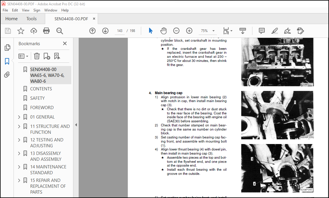
General assembly………………………………………………………….142
Special tools…………………………………………………………142
14 MAINTENANCE STANDARD……………………………………………………….161
Turbocharger……………………………………………………………..162
Cylinder head…………………………………………………………….164
Valve, valve guide………………………………………………………..166
Rocker arm shaft, push rod and tappet……………………………………….167
Cylinder block……………………………………………………………168
Cylinder…………………………………………………………………170
Crankshaft……………………………………………………………….171
Camshaft…………………………………………………………………172
Timing gear (Helical gear)…………………………………………………174
Flywheel and flywheel housing………………………………………………175
Piston, piston ring and piston pin………………………………………….176
Connecting rod……………………………………………………………178
Regulator valve…………………………………………………………..180
Water pump and thermostat………………………………………………….181
15 REPAIR AND REPLACEMENT OF PARTS……………………………………………..183
Grinding cylinder head mounting surface……………………………………..184
Replacing valve guide……………………………………………………..185
Special tools…………………………………………………………185
Grinding valve……………………………………………………………186
Special tool………………………………………………………….186
Replacing camshaft bushing…………………………………………………187
Special tools…………………………………………………………187
Replacing crankshaft gear………………………………………………….189
Testing and adjusting fuel injection timing………………………………….190
Replacing flywheel ring gear……………………………………………….191
Procedure for pressure test………………………………………………..192
Special tools…………………………………………………………192
Cylinder liner……………………………………………………………193
(special restoration part)…………………………………………………193
Cylinder liner………………………………………………………..193
Machining drawing for cylinder block bore……………………………………194
Additional machining of cam journal…………………………………………195
Grinding crankshaft……………………………………………………….196
Applicable crankshaft………………………………………………….196
Replacing connecting rod small end bushing…………………………………..197
Special tools…………………………………………………………197
More products