$36
Komatsu 95E-5 Series Engine Shop Manual SEN01966-17 – PDF DOWNLOAD
Komatsu 95E-5 Series Engine Shop Manual SEN01966-17 – PDF DOWNLOAD
FILE DETAILS:
Komatsu 95E-5 Series Engine Shop Manual SEN01966-17 – PDF DOWNLOAD
Language : English
Pages : 454
Downloadable : Yes
File Type : PDF
Size: 19.2 MB
IMAGES PREVIEW OF THE MANUAL:
DESCRIPTION:
Komatsu 95E-5 Series Engine Shop Manual SEN01966-17 – PDF DOWNLOAD
The Komatsu 95E-5 Series Engine Shop Manual SEN01966-17 is a comprehensive guide to servicing, maintaining, and repairing the Komatsu 95E-5 diesel engine. This engine is commonly used in heavy-duty machinery, such as large excavators and bulldozers.
The manual is published by Komatsu, a leading manufacturer of heavy equipment and diesel engines. It is designed to provide detailed information on the engine to qualified mechanics and technicians, enabling them to service and repair the engine to the highest standards.
The manual is divided into several sections, each of which provides specific information on different aspects of the engine. The sections include:
- General information: This section provides an overview of the engine, including its specifications, features, and operating principles. It also includes information on safety precautions, tools, and equipment needed for maintenance and repair.
- Inspection and adjustment: This section provides detailed instructions on how to inspect and adjust various components of the engine, including the cylinder head, valves, fuel system, and cooling system.
- Engine disassembly and assembly: This section provides step-by-step instructions on how to disassemble and assemble the engine. It includes detailed diagrams and illustrations to help users understand each step of the process.
- Troubleshooting: This section provides a comprehensive list of potential problems that may arise with the engine, along with diagnostic procedures to help identify and fix these issues.
- Maintenance: This section provides information on the regular maintenance tasks that should be performed on the engine, including oil changes, filter replacements, and other routine tasks.
- Reassembly and testing: This section provides detailed instructions on how to reassemble the engine after repairs have been made. It also includes information on how to test the engine to ensure that it is functioning properly.
- Service data: This section provides detailed technical data on the engine, including torque specifications, compression pressures, and other important information.
The manual is written in clear, concise language and is filled with detailed diagrams and illustrations to help users understand each step of the process. It is an essential tool for anyone who works with Komatsu diesel engines and can help to ensure that the engine is maintained and repaired to the highest standards.
However, it should be noted that the manual is designed for use by qualified mechanics and technicians and should not be used by individuals without the appropriate training and experience. The manual is also specifically for the Komatsu 95E-5 engine and should not be used as a reference for other engines in the Komatsu lineup.
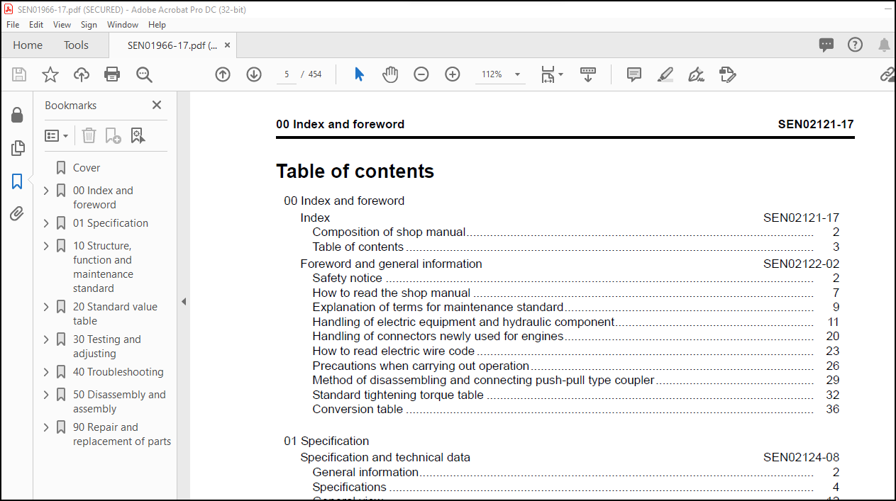
TABLE OF CONTENTS:
Komatsu 95E-5 Series Engine Shop Manual SEN01966-17 – PDF DOWNLOAD
Cover……………………………………………………………………… 1
00 Index and foreword……………………………………………………….. 0
Index………………………………………………………………….. 3
Composition of shop manual……………………………………………. 4
Table of contents……………………………………………………. 5
Foreword and general information………………………………………….. 11
Safety notice……………………………………………………….. 12
How to read the shop manual…………………………………………… 17
Explanation of terms for maintenance standard…………………………… 19
Handling of electric equipment and hydraulic component…………………… 21
Handling of connectors newly used for engines…………………………… 30
How to read electric wire code………………………………………… 33
Precautions when carrying out operation………………………………… 36
Method of disassembling and connecting push-pull type coupler…………….. 39
Standard tightening torque table………………………………………. 42
Conversion table…………………………………………………….. 46
01 Specification……………………………………………………………. 0
Specification and technical data………………………………………….. 53
General information………………………………………………….. 54
Specifications………………………………………………………. 56
General view………………………………………………………… 64
Weight table………………………………………………………… 75
Engine performance curves…………………………………………….. 76
10 Structure, function and maintenance standard………………………………… 0
Structure, function and maintenance standard, Part 1………………………… 87
General structure……………………………………………………. 90
Air intake and exhaust unit…………………………………………… 92
Air cleaner…………………………………………………………. 94
Turbocharger………………………………………………………… 96
Muffler…………………………………………………………….. 99
Cylinder head………………………………………………………..100
Cylinder block……………………………………………………….102
Cylinder…………………………………………………………….105
Main moving parts…………………………………………………….106
Crankshaft…………………………………………………………..108
Camshaft…………………………………………………………….109
Piston, piston ring and piston pin……………………………………..110
Connecting rod……………………………………………………….111
Flywheel and flywheel housing………………………………………….114
Timing gear………………………………………………………….116
Valve system…………………………………………………………120
Valve, valve guide……………………………………………………122
Rocker arm shaft, push rod and tappet…………………………………..123
Structure, function and maintenance standard, Part 2…………………………125
Lubrication system diagram…………………………………………….127
Oil pump…………………………………………………………….128
Regulator valve………………………………………………………130
Oil filter…………………………………………………………..131
Fuel system diagram…………………………………………………..133
Supply pump………………………………………………………….134
Fuel injection nozzle…………………………………………………136
Fuel filter………………………………………………………….137
Common rail………………………………………………………….138
Various sensor……………………………………………………….140
Cooling system diagram………………………………………………..142
Water pump…………………………………………………………..143
Cooling fan drive and thermostat……………………………………….146
Starting and charging system electrical circuit diagram…………………..150
Alternator…………………………………………………………..151
Starting motor……………………………………………………….155
Starting aid…………………………………………………………157
Engine controller…………………………………………………….158
20 Standard value table……………………………………………………… 0
Standard service value table………………………………………………161
Standard service value table for testing, adjusting, and troubleshooting……162
Running-in standard and performance test standard………………………..169
30 Testing and adjusting…………………………………………………….. 0
Testing and adjusting…………………………………………………….179
Testing and adjusting tools list……………………………………….181
Sketches of special tools……………………………………………..183
Measuring intake air pressure………………………………………….184
Testing exhaust temperature……………………………………………185
Adjusting valve clearance……………………………………………..186
Testing compression pressure…………………………………………..188
Testing blow-by pressure………………………………………………190
Testing oil pressure………………………………………………….191
Handling fuel system parts…………………………………………….192
Releasing residual pressure in fuel system………………………………192
Testing fuel pressure…………………………………………………193
Reduced cylinder mode operation………………………………………..194
No-injection cranking…………………………………………………194
Testing leakage from pressure limiter and return rate from injector………..195
Bleeding air from fuel circuit…………………………………………198
Testing fuel system for leakage………………………………………..200
Testing and adjusting alternator belt tension……………………………201
Handling controller voltage circuit…………………………………….202
40 Troubleshooting………………………………………………………….. 0
General information on troubleshooting……………………………………..205
Points on troubleshooting……………………………………………..206
Error code and failure code table………………………………………208
Information in troubleshooting table……………………………………210
Connection table for connector pin numbers………………………………212
T- branch box and T- branch adapter table……………………………….248
Troubleshooting of electrical system (E-mode), Part 1………………………..253
E-1 Code [111/CA111] ECM Critical Internal Failure……………………….256
E-2 Code [115/CA115] Eng. Ne and Bkup Speed Sensor Error………………….259
E-3 Code [122/CA122] Charge Air Press Sensor High Error…………………..260
E-4 Code [123/CA123] Charge Air Press Sensor Low Error……………………262
E-5 Code [131/CA131] Throttle Sensor High Error………………………….263
E-6 Code [132/CA132] Throttle Sensor Low Error…………………………..266
E-7 Code [144/CA144] Coolant Temp. Sensor High Error……………………..268
E-8 Code [145/CA145] Coolant Temp. Sensor Low Error………………………270
E-9 Code [153/CA153] Charge Air Temp. Sensor High Error…………………..272
E-10 Code [154/CA154] Charge Air Temp. Sensor Low Error…………………..274
E-11 Code [187/CA187] Sensor Sup. 2 Volt. Low Error………………………275
E-12 Code [221/CA221] Ambient Air Press. Sensor High Error………………..276
E-13 Code [222/CA222] Ambient Air Press. Sensor Low Error…………………278
E-14 Code [227/CA227] Sensor Sup. 2 Volt. High Error……………………..279
E-15 Code [234/CA234] Eng. Overspeed……………………………………280
E-16 Code [238/CA238] Ne Speed Sensor Sup. Volt. Error……………………282
E-17 Code [271/CA271] IMV Short Error…………………………………..284
E-18 Code [272/CA272] IMV Open Error……………………………………286
E-19 Code [322/CA322] Injector #1 System Open/Short Error…………………288
E-20 Code [324/CA324] Injector #3 System Open/Short Error…………………290
E-21 Code [331/CA331] Injector #2 System Open/Short Error…………………292
E-22 Code [332/CA332] Injector #4 System Open/Short Error…………………294
E-23 Code [351/CA351] INJ. Drive Circuit Error…………………………..296
E-24 Code [352/CA352] Sensor Sup. 1 Volt. Low Error………………………299
E-25 Code [386/CA386] Sensor Sup. 1 Volt. High Error……………………..300
E-26 Code [431/CA431] Idle Validation SW Low error……………………….302
E-27 Code [432/CA432] Idle Validation Process error………………………302
E-28 Code [435/CA435] Abnormality in engine oil pressure switch……………303
E-29 Code [441/CA441] Battery voltage low error………………………….304
E-30 Code [442/CA442] Battery voltage high error…………………………304
Troubleshooting of electrical system (E-mode), Part 2………………………..307
E-31 Code [449/CA449] Rail Press. Very High Error………………………..309
E-32 Code [451/CA451] Rail Press. Sensor High Error………………………310
E-33 Code [452/CA452] Rail Press. Sensor Low Error……………………….312
E-34 Code [553/CA553] Rail Press. High Error…………………………….313
E-35 Code [559/CA559] Rail Press. Low Error……………………………..314
E-36 Code [689/CA689] Eng. Ne Speed Sensor Error…………………………318
E-37 Code [731/CA731] Eng. Bkup Speed Sensor Phase Error………………….320
E-38 Code [757/CA757] All Persistent Data Lost Error……………………..321
E-39 Code [778/CA778] Eng. Bkup Speed Sensor Error……………………….322
E-40 Code [1633/CA1633] KOMNET Dtalink Timeout Error……………………..324
E-41 Code [2185/CA2185] Throttle Sens. Sup. Volt. High Error………………325
E-42 Code [2186/CA2186] Throttle Sens. Sup. Volt. Low Error……………….328
E-43 Code [2249/CA2249] Rail Press. Very Low Error……………………….329
E-44 Code [2311/CA2311] Abnormality in IMV solenoid………………………330
E-45 Code [2555/CA2555] Grid Heater Relay Volt. Low Error…………………331
E-46 Code [2556/CA2556] Grid Heater Relay Volt. High Error………………..332
E-47 Code [(—)/B@BAZG] Eng. Oil press. Low Speed Derate…………………334
E-48 Code [(—)/B@BAZG] Eng. Oil press. Torque Derate……………………334
E-49 Code [(—)/B@BCNS] Eng. Overheat………………………………….335
Troubleshooting of mechanical system (S-mode)……………………………….337
Method of using troubleshooting charts………………………………….340
S-1 Starting performance is poor……………………………………….344
S-2 Engine does not start……………………………………………..345
S-3 Engine does not pick up smoothly……………………………………348
S-4 Engine stops during operations……………………………………..349
S-5 Engine does not rotate smoothly…………………………………….350
S-6 Engine lacks output (or lacks power)………………………………..351
S-7 Exhaust smoke is black (incomplete combustion)……………………….352
S-8 Oil consumption is excessive (or exhaust smoke is blue)……………….353
S-9 Oil becomes contaminated quickly……………………………………354
S-10 Fuel consumption is excessive……………………………………..355
S-11 Oil is in coolant (or coolant spurts back or coolant level goes down)….356
S-12 Oil pressure drops……………………………………………….357
S-13 Oil level rises (Entry of coolant or fuel)………………………….358
S-14 Coolant temperature becomes too high (overheating)…………………..359
S-15 Abnormal noise is made……………………………………………360
S-16 Vibration is excessive……………………………………………361
50 Disassembly and assembly………………………………………………….. 0
General information on disassembly and assembly……………………………..363
How to read this manual……………………………………………….364
Coating materials list………………………………………………..366
Special tools list……………………………………………………369
Sketches of special tools……………………………………………..370
Disassembly and assembly, Part 1…………………………………………..373
General disassembly of engine………………………………………….374
Disassembly and assembly, Part 2…………………………………………..387
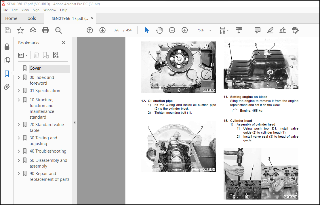
General assembly of engine…………………………………………….388
Disassembly and assembly, Part 3…………………………………………..405
Disassembly and assembly procedure for fuel supply pump unit………………406
Disassembly and assembly procedure for oil seal units…………………….408
90 Repair and replacement of parts……………………………………………. 0
Information related to repair and replacement……………………………….411
Special tool table……………………………………………………412
Sketches of special tools……………………………………………..414
Parts related to cylinder head…………………………………………….417
Part names related to cylinder head…………………………………….418
Testing and inspection of cylinder head…………………………………419
Pressure test of cylinder head…………………………………………421
Replacement of valve guide…………………………………………….421
Replacement of valve seat insert……………………………………….423
Repair of cylinder head mounting face by grinding………………………..429
Repair of valve by grinding……………………………………………430
Parts related to cylinder block……………………………………………433
Part names related to cylinder block……………………………………434
Testing and inspection of cylinder block………………………………..435
Part names related to crankshaft……………………………………….438
Testing and inspection of crankshaft……………………………………439
Part names related to connecting rod……………………………………440
Testing and inspection of connecting rod………………………………..441
Replacement of flywheel ring gear………………………………………442
Replacement of crankshaft gear…………………………………………443
Replacement of camshaft gear…………………………………………..443
Replacement of connecting rod small end bushing………………………….444
Replacement of cam bushing…………………………………………….446
Cylinder liner (Special part for repair)………………………………..448
Rework drawing for counter bore………………………………………..449
Repair of crankshaft by grinding……………………………………….450
More products