$34
Komatsu 95E-6 Series Engine Shop Manual SEN06060-05 – PDF DOWNLOAD
Komatsu 95E-6 Series Engine Shop Manual SEN06060-05 – PDF DOWNLOAD
FILE DETAILS:
Komatsu 95E-6 Series Engine Shop Manual SEN06060-05 – PDF DOWNLOAD
Language : English
Pages : 274
Downloadable : Yes
File Type : PDF
Size: 12.9 MB
IMAGES PREVIEW OF THE MANUAL:
DESCRIPTION:
Komatsu 95E-6 Series Engine Shop Manual SEN06060-05 – PDF DOWNLOAD
The Komatsu 95E-6 Series Engine Shop Manual SEN06060-05 is a comprehensive technical reference guide that provides detailed information on the maintenance, repair, and overhaul of the Komatsu 95E-6 Series diesel engine. This engine series is commonly used in heavy-duty applications such as construction equipment, mining vehicles, and marine vessels. The shop manual is an essential resource for mechanics, technicians, and service personnel who are responsible for servicing and maintaining these engines.
The Komatsu 95E-6 Series Engine Shop Manual is organized into several sections, each of which covers a specific aspect of the engine. These sections include:
- General Information: This section provides an overview of the engine, including specifications, operating guidelines, and maintenance intervals.
- Inspection and Adjustment: This section provides detailed instructions for inspecting and adjusting engine components, including the fuel injection system, valves, and timing belt.
- Engine Assembly: This section covers the removal and installation of major engine components, such as the cylinder head, crankshaft, and pistons. The manual includes detailed illustrations and specifications to help technicians perform these tasks safely and efficiently.
- Lubrication System: This section provides information on the engine’s lubrication system, including oil pump removal and installation, oil filter replacement, and oil pressure testing.
- Cooling System: This section provides information on the engine’s cooling system, including water pump removal and installation, radiator removal and installation, and thermostat replacement.
- Fuel System: This section covers the engine’s fuel system, including fuel pump removal and installation, fuel injector replacement, and fuel system troubleshooting.
- Air Intake and Exhaust System: This section provides information on the engine’s air intake and exhaust system, including air filter replacement, turbocharger removal and installation, and exhaust manifold removal and installation.
- Electrical System: This section provides information on the engine’s electrical system, including alternator and starter motor removal and installation, as well as troubleshooting procedures for electrical faults.
- Special Tools: This section lists the special tools required for servicing the engine, including part numbers and illustrations.
The Komatsu 95E-6 Series Engine Shop Manual SEN06060-05 is an essential resource for maintaining and repairing these engines. It provides a comprehensive guide to servicing the engine and includes detailed instructions, specifications, and illustrations to help technicians perform tasks accurately and safely. The manual is a valuable tool for ensuring that the Komatsu 95E-6 Series diesel engine continues to operate at peak performance, with maximum efficiency and reliability over its long service life.
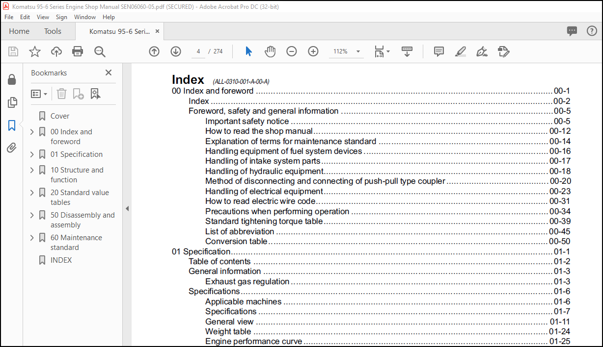
TABLE OF CONTENTS:
Komatsu 95E-6 Series Engine Shop Manual SEN06060-05 – PDF DOWNLOAD
Cover……………………………………………………………… 1
00 Index and foreword ………………………………………………. 3
Index …………………………………………………………. 4
Foreword, safety and general information ………………………….. 7
Important safety notice ……………………………………… 7
How to read the shop manual ………………………………….. 14
Explanation of terms for maintenance standard ………………….. 16
Handling equipment of fuel system devices ……………………… 18
Handling of intake system parts ………………………………. 19
Handling of hydraulic equipment ………………………………. 20
Method of disconnecting and connecting of push-pull type coupler …. 22
Handling of electrical equipment ……………………………… 25
How to read electric wire code ……………………………….. 33
Precautions when performing operation …………………………. 36
Standard tightening torque table ……………………………… 41
List of abbreviation ………………………………………… 47
Conversion table ……………………………………………. 52
01 Specification …………………………………………………… 57
Table of contents ………………………………………………. 58
General information …………………………………………….. 59
Exhaust gas regulation ………………………………………. 59
Specifications …………………………………………………. 62
Applicable machines …………………………………………. 62
Specifications ……………………………………………… 63
General view ……………………………………………….. 67
Weight table ……………………………………………….. 80
Engine performance curve …………………………………….. 81
10 Structure and function …………………………………………… 85
Table of contents ………………………………………………. 86
Components layout ………………………………………………. 87
Components layout drawing ……………………………………. 87
Intake and exhaust system parts ………………………………….. 89
Intake and exhaust system layout drawing ………………………. 89
Intake and exhaust system circuit diagram ……………………… 91
Air cleaner(DF type) ………………………………………… 93
Air cleaner(FPG type) ……………………………………….. 94
Variable flow turbocharger …………………………………… 95
EGR system piping drawing ……………………………………. 99
EGR system circuit diagram ……………………………………101
EGR valve …………………………………………………..102
EGR cooler ………………………………………………….104
KCCV layout drawing ………………………………………….106
KCCV ventilator ……………………………………………..108
KDOC muffler ………………………………………………..112
Engine main body parts …………………………………………..114
General structure ……………………………………………114
Cylinder head ……………………………………………….118
Cylinder block ………………………………………………120
Main moving parts ……………………………………………122
Timing gear …………………………………………………125
Front cover …………………………………………………127
Valve system ………………………………………………..128
Flywheel and flywheel housing …………………………………130
Lubrication system ………………………………………………131
Lubrication system chart ……………………………………..131
Oil pump ……………………………………………………133
Oil filter ………………………………………………….135
Oil cooler ………………………………………………….137
Oil pan …………………………………………………….138
Fuel system …………………………………………………….139
Fuel system parts layout drawing ………………………………139
Fuel system circuit diagram …………………………………..141
Prefilter …………………………………………………..142
Main filter …………………………………………………143
Supply pump …………………………………………………144
Common rail …………………………………………………145
Injector ……………………………………………………146
Cooling system ………………………………………………….150
Cooling system parts layout drawing ……………………………150
Cooling system chart …………………………………………151
Drive pulley ………………………………………………..152
Water pump ………………………………………………….154
Thermostat and jiggle valve …………………………………..155
Electrical equipment …………………………………………….159
Alternator ………………………………………………….159
Starting motor ………………………………………………164
Intake air heater ……………………………………………168
Engine harness ………………………………………………169
Engine controller ……………………………………………171
Sensor ……………………………………………………..177
20 Standard value tables …………………………………………….185
Table of contents ……………………………………………….186
Standard service value table ……………………………………..187
Standard value table for engine ……………………………….187
Running-in standard and performance test standard ……………….193
50 Disassembly and assembly ………………………………………….197
Table of contents ……………………………………………….198
Related information on disassembly and assembly …………………….199
How to read this manual ………………………………………199
Coating materials list ……………………………………….201
Special tools list …………………………………………..205
Sketches of special tools …………………………………….206
Disassembly and assembly …………………………………………207
General disassembly of engine …………………………………207
General assembly of engine ……………………………………222
Removal and installation procedure of supply pump unit alone ……..245
Engine front oil seal replacement procedure …………………….248
Engine rear oil seal replacement procedure ……………………..249
60 Maintenance standard ……………………………………………..251
Table of contents ……………………………………………….252
Intake and exhaust system parts …………………………………..253
Variable flow turbocharger ……………………………………253
Engine main body parts …………………………………………..254
Cylinder head ……………………………………………….254
Cylinder block ………………………………………………256
Crankshaft ………………………………………………….258
Piston ……………………………………………………..259
Connecting rod ………………………………………………260
Timing gear …………………………………………………261
Camshaft ……………………………………………………262
Valve system ………………………………………………..263
Valve and valve guide ………………………………………..264
Rocker arm shaft, push rod, and tappet …………………………265
Flywheel and flywheel housing …………………………………266
Lubrication system ………………………………………………268
Oil pump ……………………………………………………268
Cooling system ………………………………………………….270
Water pump ………………………………………………….270
INDEX………………………………………………………………271
More products