$45
Komatsu D150A-1, D155A-1 Bulldozer Shop Manual PDF DOWNLOAD
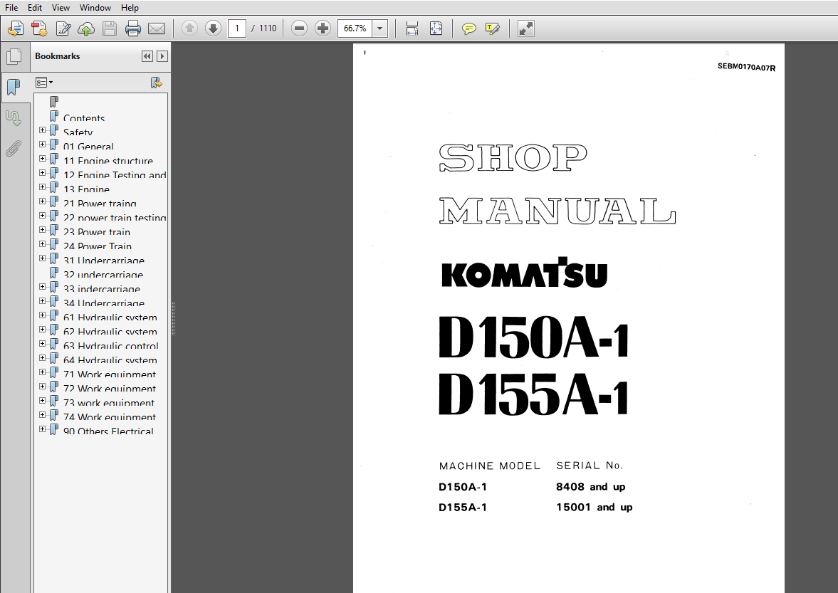
Komatsu D150A-1 D155A-1 Bulldozer WorkShop Service Repair Manual
DESCRIPTION:
Komatsu D150A-1 D155A-1 Bulldozer WorkShop Service Repair Manual
FOREWORD:
This shop manual has been prepared as an aid to improve the quality of repairs by giving the servicemen an accurate understanding of the product and by showing him the correct way to perform repairs and make judgements. Make sure you understand the contents of this manual and use it to full effect at every opportunity. This shop manual mainly contains the necessary technical information for operations performed in a service workshop. For ease of understanding. the manual is divided into chapters for each main group of components: these chapters are further divided into the following sections.
STRUCTURE AND FUNCTION
Ths section explains the structure and function of each component. It serves not only to give an understanding of the structure, but also serves as reference material for troubleshooting.
TESTING AND ADJUSTING
Ths section explains checks to be made before and after performing repairs, as well as adjustments to be made at completion of the checks and repairs. Troubleshooting charts correlating ”Problems” to “Causes” are also included in this section.
DISASSEMBLY AND ASSEMBLY
The section explains the order to be followed when removing, installing, disassembling or assembling each component, as well as precautions to be taken for these operations.
MAINTENANCE STANDARD
Ths section gives the judgement standards when inspecting disassembled parts.
TABLE OF CONTENTS:
Komatsu D150A-1 D155A-1 Bulldozer WorkShop Service Repair Manual
Contents....................................................   2
Safety......................................................   9
	How to read the shop manual.............................  12
	Hoisting instructions...................................  13
	Standard tightening torque..............................  14
01 General..................................................  17
	Specifications..........................................  28
	General assembly drawing................................  30
	Engine specifications...................................  43
	Weight table............................................  46
	Position of serial numbers (Engine).....................  52
	Position of serial numbers (body).......................  53
	Table of oil and coolant................................  54
11 Engine structure and function............................  61
	Radiator, fan...........................................  64
	Oil cooler..............................................  70
	P.T.O...................................................  71
	Engine control..........................................  72
	Fuel piping.............................................  73
12 Engine Testing and adjusting.............................  75
	Tool list...............................................  78
	Trouble shooting criteria...............................  79
	General instructions....................................  84
	Intake ans exhaust system...............................  86
	Engine body.............................................  90
	Lubrication system......................................  92
	Fuel system.............................................  94
13 Engine disassembly and assembly..........................  97
	Dismounting turbocharger................................ 100
	mounting turbocharger................................... 102
	Dismounting engine oil cooler........................... 104
	Mounting engine oil cooler.............................. 108
	torque convertor oil cooler............................. 112
	Nozzle holder........................................... 118
	Fuel injection pump..................................... 122
	Fan belt................................................ 128
	Water pump.............................................. 130
	Starting motor.......................................... 134
	Alternator.............................................. 137
	Cylinder head........................................... 142
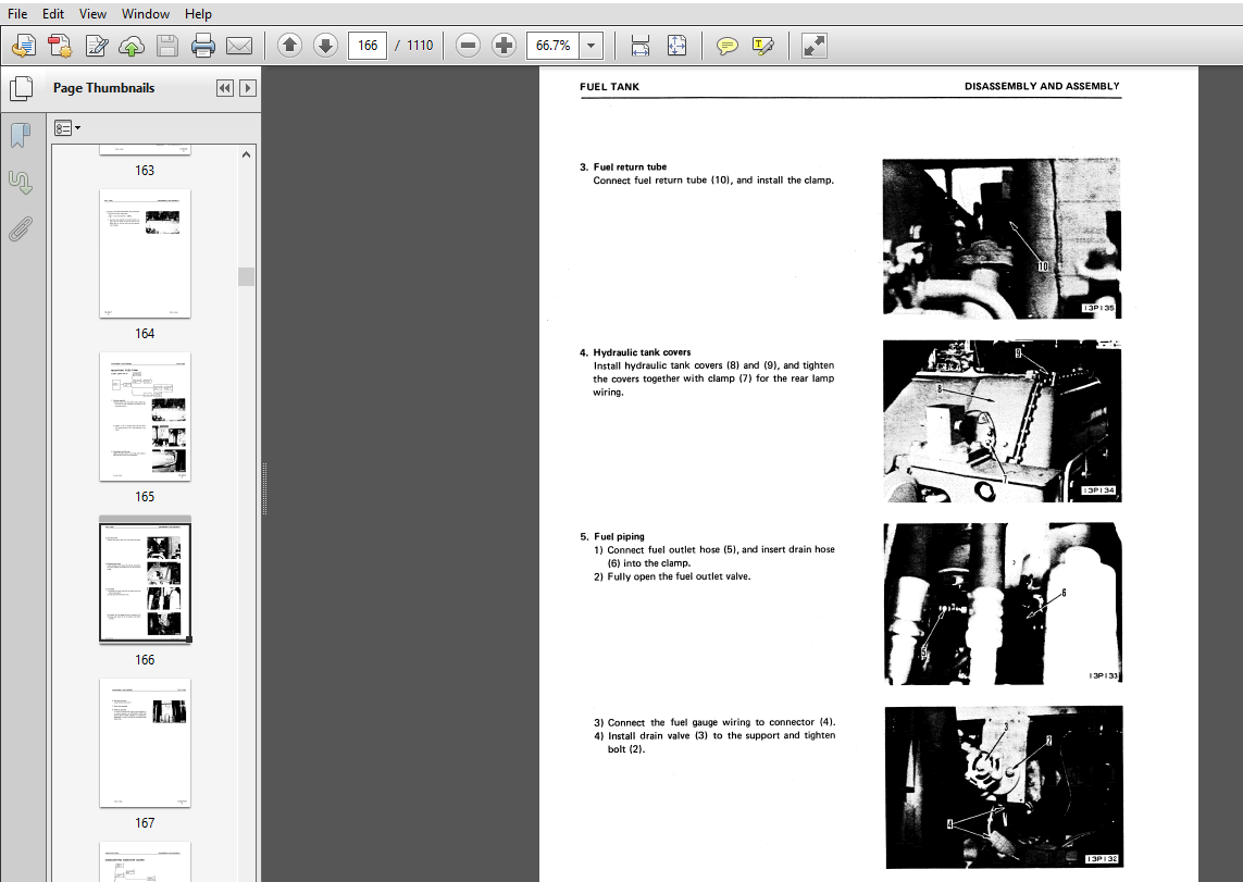
	Fuel tank............................................... 158
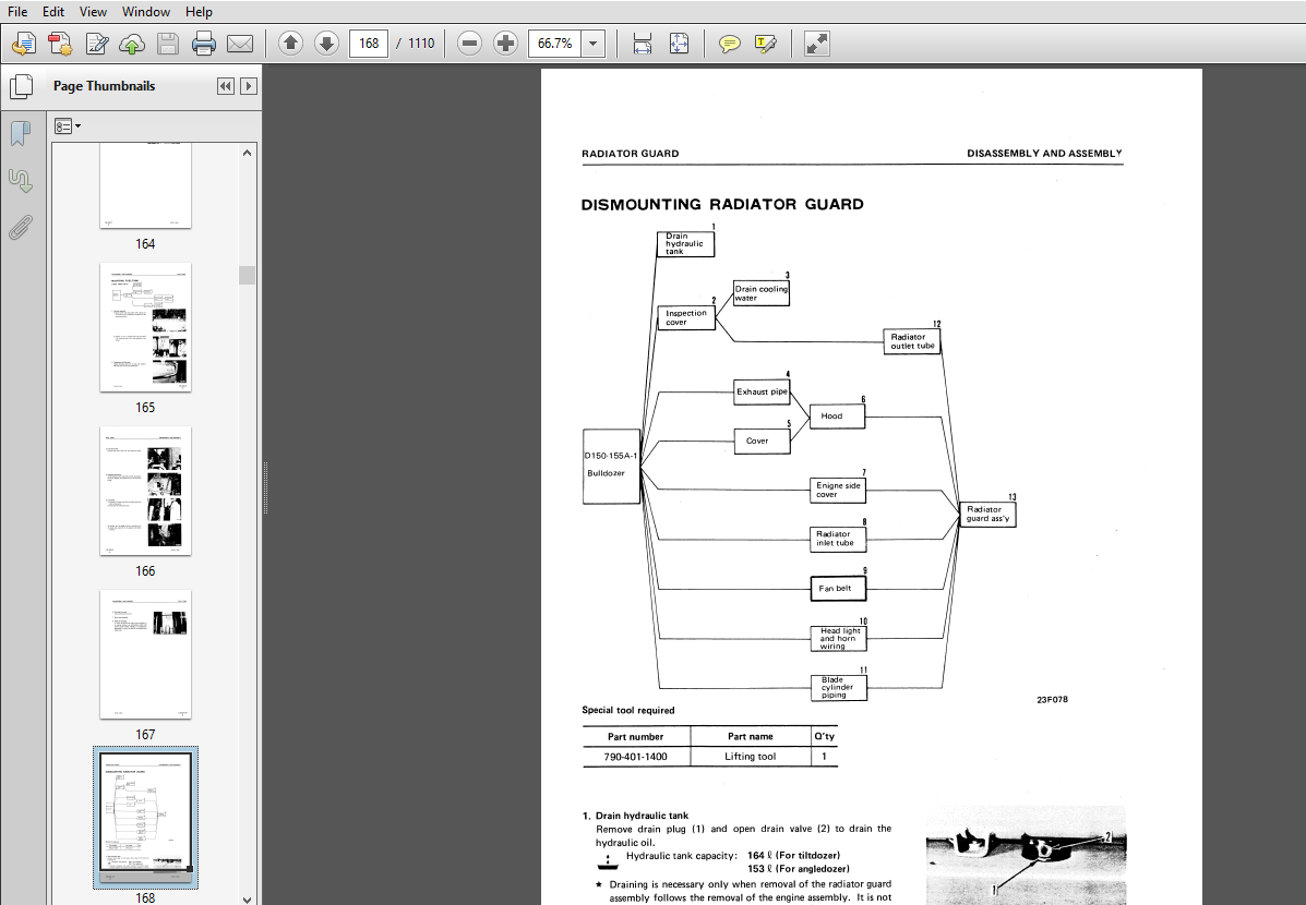
	Radiator guard.......................................... 168
	Radiator................................................ 176
	Engine.................................................. 190
21 Power traing Structure and functions..................... 237
	General................................................. 240
	Main clutch............................................. 244
	Inertia brake........................................... 248
	Transmisssion D150A..................................... 254
	Double mesh preventive device........................... 261
	Torque convertor........................................ 264
	Transmission D155A...................................... 268
	Torqflow................................................ 278
	Transmission lubrication relief vanlve.................. 286
	Transmission control valve.............................. 287
	Transmission pump....................................... 295
	Bevel gear shaft and steering clutch.................... 298
	Steering and brake piping............................... 302
	steering hydraulic system............................... 306
	Brake hydraulic system.................................. 310
	Steering brake and booster D150A AND D155A.............. 314
		Steering control valve.............................. 318
		Steering and brake piping........................... 324
		Steering and brake hydraulic circuit................ 327
	Steering brake and booster D155A 25001.................. 328
	Steering control valve d155a 25001...................... 334
	Steering pump........................................... 339
	Final drive............................................. 341
22 power train testing and adjusting........................ 345
	Main clutch hydraulic control........................... 350
	Torqflow hydraulic control.............................. 352
	Steering hydraulic control.............................. 358
	Brake hydraulic control................................. 364
	Table of oil pressure measuring points.................. 368
	Procedure for measuring oil pressure and temperature.... 376
	Procedure for measurment of lever and pedal travel...... 382
	Adjustment procedure for strokes........................ 386
	Adjusting main clutch................................... 390
	Table of maintenance standerds.......................... 392
23 Power train disassembly and assembly..................... 395
	pto and flywheel........................................ 400
	Main clutch............................................. 408
	Transmission assembly................................... 416
	Torque convertor........................................ 434
	Torque convertor relief valve........................... 468
	Torque converter regulator valve........................ 472
	Torqflow transmission D155 15001 - 25000................ 476
	Torqflow transmission D155A Sn 25001.................... 516
		Mounting Torqflow transmission...................... 521
		Dismounting Transmission control valve.............. 526
		Mounting transmission control valve................. 528
		Transmission lubrication valve...................... 535
		Steering clutch..................................... 538
	Bevel gear and bevel gear shaft......................... 558
	Final drive............................................. 568
	Steering control valve.................................. 574
	Steering brake interlocking valve....................... 578
	Brake safety valve...................................... 586
	Brake booster........................................... 594
	Final drive............................................. 600
	Torqflow pump........................................... 614
	Steering pump........................................... 618
	Torque converter oil cooler............................. 622
	Floor frame............................................. 630
	Rops cab................................................ 642
	Fuel tank............................................... 656
	Radiator................................................ 660
	Radiator guard.......................................... 668
24 Power Train Maintenance standard......................... 677
	Transmission............................................ 692
	Bevel gear shaft and steering system.................... 706
	Final drive............................................. 720
31 Undercarriage Structure and function..................... 723
	Track................................................... 726
	Track group............................................. 730
	Recail spring........................................... 731
	Idler................................................... 732
	Track roller, carrier roller............................ 733
	Suspension.............................................. 734
32 undercarriage Testing and adjusting...................... 737
33 indercarriage Disassembly and assembly................... 739
	track................................................... 742
	Carrier roller.......................................... 750
	Track roller............................................ 754
	Idler................................................... 758
	Recoil spring........................................... 762
	Track frame............................................. 774
34 Undercarriage maintenance standard....................... 779
	Undercarriage........................................... 782
61 Hydraulic system structure and function.................. 797
	Hydraulic control....................................... 800
	Hydraulic tank.......................................... 810
	Hydraulic control valve................................. 812
	Ripper selector valve and pilot check valve............. 816
	Pin puller valve........................................ 820
	Pilot valve............................................. 824
	Rotary servo valve...................................... 827
	Servo valve hydralic control/valve...................... 830
	Safety valve............................................ 833
	Cylinders............................................... 834
	Piston valve............................................ 836
	Hydraulic control....................................... 838
62 Hydraulic system testing and adjusting................... 863
	General description..................................... 866
	Hydraulic control....................................... 868
	Pin puller control...................................... 870
	Measurment of oil pressure and temperature.............. 871
	Measurment of operating force........................... 875
	Table of maintance standard............................. 878
63 Hydraulic control sysyem Disassembly and assembly........ 881
	Disassembly and assembly................................ 883
	Hydraulic pump.......................................... 886
	Hydraulic tank.......................................... 890
	Ripper & blade control valve............................ 898
	Blade tilt control valve................................ 909
	Blade tilt servo valve.................................. 914
	Ripper servo valve...................................... 922
	Ripper pin puller valve................................. 926
	Ripper selector valve................................... 934
	Blade lift cylinder..................................... 953
	Blade tilt cylinder..................................... 970
	Ripper lift & Tilt cylinder............................. 986
	Ripper pin puller cylinder..............................1006
64 Hydraulic system Maintance standard......................1009
	Torque specifications for nuts and bolts................1010
	Hydraulic control valve.................................1012
	Cylinders...............................................1021
71 Work equipment structure and function....................1025
	Multi ripper............................................1030
	Giant ripper............................................1034
72 Work equipment testing and adjustment....................1041
	Straight tilt dozer.....................................1044
73 work equipment disassembly & assembly....................1047
	Blade...................................................1050
	Ripper..................................................1061
74 Work equipment Maintenance standard......................1073
	Torque specifications...................................1074
	Straight tilt dozer.....................................1076
	Multi ripper............................................1080
	Giant ripper............................................1082
90 Others Electrical system.................................1085
	Electical circuit diagram...............................1088
	Electical wiring diagram................................1096
	Warning module..........................................1099
	Automatic priming system................................1102
IMAGES PREVIEW OF THE MANUAL:
