$36
Komatsu D355C-3 Pipelayer Shop Manual SEBM029903 – PDF DOWNLOAD
Komatsu D355C-3 Pipelayer Shop Manual SEBM029903 – PDF DOWNLOAD
FILE DETAILS:
Komatsu D355C-3 Pipelayer Shop Manual SEBM029903 – PDF DOWNLOAD
Language : English
Pages : 793
Downloadable : Yes
File Type : PDF
Size: 105.6 MB
IMAGES PREVIEW OF THE MANUAL:
DESCRIPTION:
Komatsu D355C-3 Pipelayer Shop Manual SEBM029903 – PDF DOWNLOAD
Machine model Serial number
D355C-3 14263 and up
GENERAL PRECAUTIONS:
Mistakes in operation are extremely dangerous. Read the Operation and Maintenance Manual carefully BEFORE operating the machine.1 .Before carrying out any greasing or repairs, read all the precautions given on the decals which are fixed to the machine.
2.When carrying out any operation, always wear safety shoes and helmet. Do not wear loose work clothes, or clothes with buttons missing.
- Always wear safety glasses when hitting parts with a hammer.
- Always wear safety glasses when grinding parts with a grinder, etc.
3. If welding repairs are needed, always have a trained, experienced welder carry out the work. When carrying out welding work, always wear welding gloves, apron, glasses, cap and other clothes suited for welding work.4.When carrying out any operation with two or more workers, always agree on the op- erating procedure before starting. Always inform your fellow workers before starting any step of the operation. Before starting work, hang UNDER REPAIR signs on the controls in the operator’s compartment.5. Keep all tools in good condition and learn the correct way to use them.
6. Decide a place in the repair workshop to keep tools and removed parts. Always keep the tools and parts in their correct places. Always keep the work area clean and make sure that there is no dirt or oil on the floor. Smoke only in the areas provided for smoking. Never smoke while working.PREPARATIONS FOR WORK:
7. Before adding or making any repairs, park the machine on hard, level ground, and block the wheels to
prevent the machine from moving.
8. Before starting work, lower outrigger, bucket or any other work equipment to the ground. If this is not possible,
use blocks to prevent the work equipment from falling down. In addition, be sure to lock all the control levers and hang warning sign on them.
9. When disassembling or assembling, support the machine with blocks, jacks or stands before starting
work.
10. Remove all mud and oil from the steps or other places used to get on and off the machine. Always use the handrails, ladders or steps when getting on or off the machine.Never jump on or off the machine. If it is impossible to use the handrails, ladders or steps, use a stand to provide safe footing.
TABLE OF CONTENTS:
Komatsu D355C-3 Pipelayer Shop Manual SEBM029903 – PDF DOWNLOAD
COVER…………………………………………………………………………………………………………………….. 1
01 General………………………………………………………………………………………………………………… 27
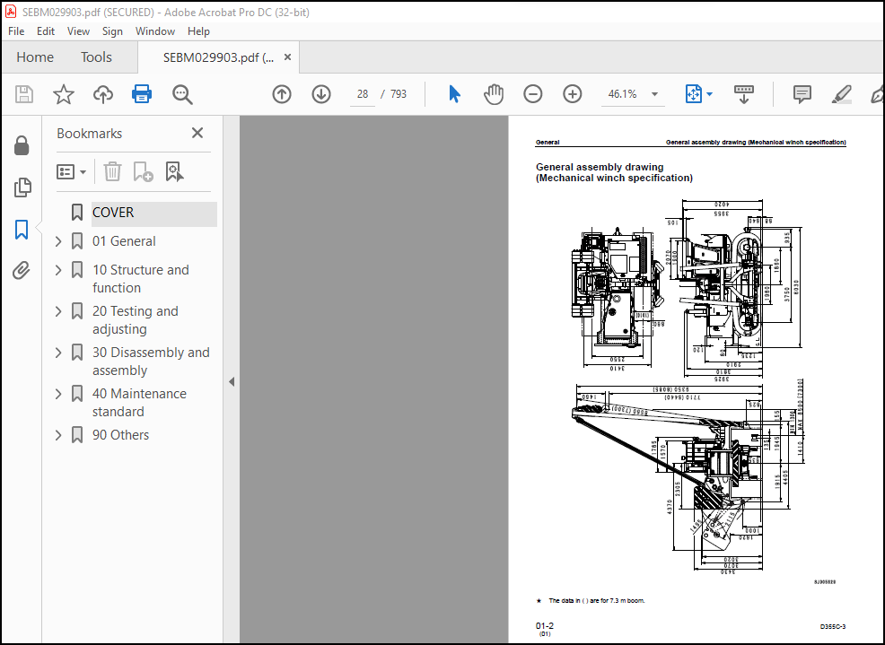
General assembly drawing (Mechanical winch specification)…………………………………………………………………… 28
General assembly drawing (Hydraulic winch specification)……………………………………………………………………. 29
Specifications (Mechanical winch specification)……………………………………………………………………………. 30
Specifications (Hydraulic winch specification)…………………………………………………………………………….. 35
Weight table (Mechanical winch specification)……………………………………………………………………………… 40
Weight table (Hydraulic winch specification)………………………………………………………………………………. 42
Table of fuel, coolant and lubricants (Mechanical winch specification)……………………………………………………….. 44
Table of fuel, coolant and lubricants (Hydraulic winch specification)………………………………………………………… 47
10 Structure and function…………………………………………………………………………………………………… 49
Radiator fan…………………………………………………………………………………………………………… 50
Radiator shutter……………………………………………………………………………………………………….. 52
PTO (Power Take-Off) (Mechanical winch specification/Hydraulic winch specification)……………………………………………. 54
Oil cooler…………………………………………………………………………………………………………….. 56
Power train diagram…………………………………………………………………………………………………….. 58
TORQFLOW hydraulic circuit………………………………………………………………………………………………. 60
Power train hydraulic circuit diagram…………………………………………………………………………………….. 62
Torque converter……………………………………………………………………………………………………….. 64
Transmission control……………………………………………………………………………………………………. 67
TORQFLOW transmission…………………………………………………………………………………………………… 69
Transmission control valve………………………………………………………………………………………………. 76
Transmission lubrication valve…………………………………………………………………………………………… 81
Steering and brake control………………………………………………………………………………………………. 82
Bevel gear shaft and steering clutches……………………………………………………………………………………. 84
Steering and brake hydraulic piping………………………………………………………………………………………. 88
Steering and brake hydraulic circuit diagram………………………………………………………………………………. 90
Steering brakes………………………………………………………………………………………………………… 92
Steering control valve………………………………………………………………………………………………….. 96
Final drive…………………………………………………………………………………………………………….102
Track group…………………………………………………………………………………………………………….105
Recoil spring…………………………………………………………………………………………………………..106
Suspension……………………………………………………………………………………………………………..107
Winch control (Mechanical winch specification)……………………………………………………………………………..109
Hydraulic circuit diagram for winch (Mechanical winch specification)………………………………………………………….112
Winch (Mechanical winch specification)…………………………………………………………………………………….114
Detailed working circuit diagram for clutch and brake of winch (Mechanical winch specification)………………………………….119
Power train on winch (Mechanical winch specification)……………………………………………………………………….121
High-Low valve (Mechanical winch specification)…………………………………………………………………………….127
PPC valve (Mechanical winch specification)…………………………………………………………………………………128
Flow divider valve (Mechanical winch specification)…………………………………………………………………………131
Counterweight hydraulic tank (Mechanical winch specification)………………………………………………………………..133
Counterweight piping (Mechanical winch specification)……………………………………………………………………….134
Counterweight control (Mechanical winch specification)………………………………………………………………………135
Counterweight hydraulic circuit diagram (Mechanical winch specification)………………………………………………………136
Counterweight…………………………………………………………………………………………………………..137
Counterweight control valve (Mechanical winch specification)…………………………………………………………………138
Winch control (Hydraulic winch specification)………………………………………………………………………………139
Winch (Hydraulic winch specification)……………………………………………………………………………………..142
PPC valve for boom/counterweight (Hydraulic winch specification)……………………………………………………………..146
PPC valve for hook (Hydraulic winch specification)………………………………………………………………………….147
Hydraulic tank (Hydraulic winch specification)……………………………………………………………………………..151
Piping drawing of counterweight (Hydraulic winch specification)………………………………………………………………152
Counterweight control (Hydraulic winch specification)……………………………………………………………………….153
CLSS (Winch and counterweight control) (Hydraulic winch specification)………………………………………………………..155
Main pump (Hydraulic winch specification)………………………………………………………………………………….158
Control valve (Winch and counterweight control valve) (Hydraulic winch specification)…………………………………………..174
Winch (boom and hook) motor (Hydraulic winch specification)………………………………………………………………….197
Boom…………………………………………………………………………………………………………………..207
Safety device (Mechanical winch specification)……………………………………………………………………………..208
Safety device (Hydraulic winch specification)………………………………………………………………………………212
Cab……………………………………………………………………………………………………………………216
Heater…………………………………………………………………………………………………………………217
Actual electric wiring diagram (Mechanical winch specification)1……………………………………………………………..218
20 Testing and adjusting…………………………………………………………………………………………………….219
Standard value table for engine related parts………………………………………………………………………………220
Standard value table for chasss (Mechanical winch specification)……………………………………………………………..221
Standard value table for chassis (Hydraulic winch specification)……………………………………………………………..225
Testing and adjusting……………………………………………………………………………………………………229
Tools for testing, adjusting, and troubles……………………………………………………………………………..230
Adjusting valve clearance…………………………………………………………………………………………….231
Testing compression pressure………………………………………………………………………………………….232
Testing and adjusting fuel injection timing…………………………………………………………………………….233
Testing engine oil pressure…………………………………………………………………………………………..234
Testing exhaust color………………………………………………………………………………………………..235
Testing exhaust temperature…………………………………………………………………………………………..236
Testing and adjusting alternator belt tension…………………………………………………………………………..237
Testing blowby………………………………………………………………………………………………………238
Testing air supply pressure (boost pressure)……………………………………………………………………………239
Testing engine speed…………………………………………………………………………………………………240
Testing torque converter stall speed…………………………………………………………………………………..241
Bleeding air from counterweight cylinder……………………………………………………………………………….242
Adjusting winch control linkage (Mechanical winch specification)………………………………………………………….244
Adjusting winch control interlock mechanism (Mechanical winch specification)……………………………………………….246
Releasing procedure for winch drum…………………………………………………………………………………….247
Testing power train oil pressure………………………………………………………………………………………249
Testing counterweight oil pressure (Mechanical winch specification)……………………………………………………….251
Testing winch oil pressure (Mechanical winch specification)………………………………………………………………252
Hydraulic circuit diagram for winch (Mechanical winch specification)………………………………………………………253
Air bleeding procedure for hydraulic circuit (Hydraulic winch specification)……………………………………………….254
Testing and adjusting work equipment circuit oil pressure (Hydraulic winchspecification)…………………………………….256
Measuring source pressure of control circuit (Hydraulic winch specification)……………………………………………….259
Testing and adjusting oil pressure in pump PC control circuit (Hydraulic winch specification)………………………………..260
Testing and adjusting oil pressure in pump LS control circuit (Hydraulic winch specification)………………………………..263
Testing solenoid valve outlet pressure (Mechanical winch specification)……………………………………………………266
Testing PPC valve outlet pressure (Hydraulic winch specification)…………………………………………………………270
Testing leakage inside cylinder……………………………………………………………………………………….271
Reinstallation (if moment limiter was removed) and adjusting……………………………………………………………..272
Adjustment procedure for moment limiter performance……………………………………………………………………..273
Troubleshooting…………………………………………………………………………………………………………277
Points to remember when troubleshooting………………………………………………………………………………..278
Sequence of events in troubleshooting………………………………………………………………………………….279
Points to remember when carrying out maintenance………………………………………………………………………..280
Checks before troubleshooting…………………………………………………………………………………………288
Troubleshooting of engine system (S mode)………………………………………………………………………………289
Method of using troubleshooting charts……………………………………………………………………………..290
S-1 Starting performance is poor (starting always takes time)…………………………………………………………294
S-2 Engine does not start…………………………………………………………………………………………295
(1) Engine does not turn………………………………………………………………………………………295
(2) Engine turns but no exhaust smoke comes out (fuel is not being injected)………………………………………..296
(3) Exhaust smoke comes out but engine does not start (Fuel is being injected)………………………………………297
S-3 Engine does not pick up smoothly (follow-up is poor)……………………………………………………………..298
S-4 Engine stops during operations…………………………………………………………………………………299
S-5 Engine does not rotate smoothly (hunting)……………………………………………………………………….300
S-6 Engine lacks output (no power)…………………………………………………………………………………301
S-7 Exhaust smoke is black (incomplete combustion)…………………………………………………………………..302
S-8 Oil consumption is excessive (or exhaust smoke is blue)…………………………………………………………..303
S-9 Oil becomes contaminated quickly……………………………………………………………………………….304
S-10 Fuel consumption is excessive…………………………………………………………………………………305
S-11 Oil is in cooling water, or water spurts back, or water level goes down……………………………………………306
S-12 Oil pressure caution lamp lights up (drop in oil pressure)……………………………………………………….307
S-13 Oil level rises (water, fuel in oil)…………………………………………………………………………..308
S-14 Water temperature becomes too high (overheating)………………………………………………………………..309
S-15 Abnormal noise is made……………………………………………………………………………………….310
S-16 Vibration is excessive……………………………………………………………………………………….311
Troubleshooting of hydraulic, mechanical system (H mode)…………………………………………………………………313
Mechanical winch specification…………………………………………………………………………………….315
H-1 Torque converter oil temperature is too high (Mechanical winch specification)……………………………………315
H-2 Machine does not move (Mechanical winch specification)………………………………………………………..316
H-3 Machine lacks power or speed (Mechanical winch specification)………………………………………………….317
H-4 Machine moves when engine is started (Mechanical winch specification)…………………………………………..318
H-5 Excessive time lag when starting machine or shifting gear (Mechanical winch specification)………………………..318
H-6 Excessive shock when starting off or shifting gear (Mechanical winch specification)………………………………319
H-7 Machine moves in only one direction (FORWARD or REVERSE) (Mechanical winch specification)…………………………320
H-8 Steering clutch is not disengaged (Mechanical winch specification)……………………………………………..321
H-9 Steering clutch slips (Mechanical winch specification)………………………………………………………..322
H-10 Steering brake does not work (Mechanical winch specification)…………………………………………………323
H-11 Lack of power, speed when retract counterweight (Mechanical winch specification)………………………………..324
H-12 Impossible to retract counterweight (Mechanical winch specification)…………………………………………..325
H-13 Excessive hydraulic drift of counterweight cylinder (Mechanical winch specification)…………………………….326
H-14 Defective boom RAISE, LOWER (speed, raising force, lowering force) (Mechanical winch specification)……………….327
H-15 Defective hook RAISE, LOWER (speed, raising force, lowering force) (Mechanical winch specification)……………….328
H-16 Excessive hydraulic drift of boom (Mechanical winch specification)…………………………………………….329
H-17 Excessive hydraulic drift of hook (Mechanical winch specification)…………………………………………….330
H-18 Play when operating hook (Mechanical winch specification)…………………………………………………….331
H-19 Play when operating boom (Mechanical winch specification)…………………………………………………….332
H-20 Excessive time lag when operating hook (Mechanical winch specification)………………………………………..333
H-21 Excessive time lag when operating boom (Mechanical winch specification)………………………………………..334
H-22 Excessive inching amount (Mechanical winch specification)…………………………………………………….335
H-23 Winch free fall does not work (Mechanical winch specification)………………………………………………..336
H-24Winch overheats (Mechanical winch specification)……………………………………………………………..337
H-25 Excessive noise when operating winch clutch, brake (Mechanical winch specification)……………………………..338
H-26 Control lever is heavy (Mechanical winch specification)………………………………………………………339
H-27 Hook overwind horn does not sound (Mechanical winch specification)…………………………………………….340
Hydraulic winch specifications…………………………………………………………………………………….342
Hydraulic and mechanical system diagram (Hydraulic winch specifications)……………………………………………342
Information described in troubleshooting table…………………………………………………………………..344
H-28 Work equipment operates slowly or lacks power (Hydraulic winch specifications)………………………………….345
H-29 Engine speed drops significantly or engine stalls (Hydraulic winch specifications)………………………………346
H-30 Work equipment does not operate. (Hydraulic winch specifications)……………………………………………..347
H-31 Unusual noise is heard from around hydraulic pump (Hydraulic winch specifications)………………………………347
H-32 Fine control performance or response is poor (Hydraulic winch specifications)…………………………………..348
H-33 Boom speed or power is low (Hydraulic winch specifications)…………………………………………………..349
H-34 Hook speed or power is low (Hydraulic winch specifications)…………………………………………………..350
H-35 Counterweight speed or power is low (Hydraulic winch specifications)…………………………………………..351
H-36 Work equipment does not move in single operation (Hydraulic winch specifications)……………………………….351
H-37 Hydraulic drift of counterweight is large (Hydraulic winch specifications)……………………………………..352
H-38 Time lag of work equipment is large (Hydraulic winch specifications)…………………………………………..353
H-39 When certain work equipment is relieved hydraulically, other work equipment moves (Hydraulic winch specifications)….353
30 Disassembly and assembly………………………………………………………………………………………………….355
How to read this manual………………………………………………………………………………………………….357
Coating materials list…………………………………………………………………………………………………..359
Special tool list……………………………………………………………………………………………………….363
Sketches of special tools………………………………………………………………………………………………..368
Removal and installation of starting motor assembly…………………………………………………………………………376
Removal and installation of alternator assembly…………………………………………………………………………….377
Removal and installation of engine oil cooler core assembly………………………………………………………………….379
Removal and installation of fuel injection pump assembly…………………………………………………………………….381
Removal and installation of water pump assembly…………………………………………………………………………….383
Removal and installation of turbocharger assembly…………………………………………………………………………..386
Removal and installation of nozzle holder assembly………………………………………………………………………….388
Removal and installation of cylinder head assembly………………………………………………………………………….389
Removal and installation of thermostat assembly…………………………………………………………………………….401
Removal and installation of radiator assembly………………………………………………………………………………402
Removal and installation of fuel tank assembly (Mechanical winch specification)………………………………………………..413
Removal and installation of fuel tank assembly (Hydraulic winch specification)…………………………………………………415
Removal and installation of torque converter and winch cooler assembly………………………………………………………..417
Removal and installation of engine assembly………………………………………………………………………………..419
Removal and installation of transmission pump assembly………………………………………………………………………428
Removal and installation of floor frame assembly (Mechanical winch specification)………………………………………………429
Removal and installation of floor frame assembly (Hydraulic winch specification)……………………………………………….436
Removal and installation of torque converter assembly……………………………………………………………………….442
Disassembly and assembly of torque converter assembly……………………………………………………………………….447
Removal and installation of torque converter relief valve assembly……………………………………………………………462
Removal and installation of torque converter regulating valve assembly………………………………………………………..463
Removal and installation of transmission control valve assembly………………………………………………………………464
Removal and installation of TORQFLOW transmission assembly…………………………………………………………………..467
Disassembly and assembly of TORQFLOW transmission assembly…………………………………………………………………..485
Removal and installation of steering control valve assembly………………………………………………………………….511
Disassembly and assembly of steering control valve assembly………………………………………………………………….513
Removal and installation of brake safety valve assembly……………………………………………………………………..517
Disassembly and assembly of brake safety valve assembly……………………………………………………………………..518
Removal and installation of transmission lubrication valve assembly…………………………………………………………..519
Removal and installation of steering pump assembly………………………………………………………………………….520
Removal and installation of steering clutch assembly………………………………………………………………………..521
Disassembly and assembly of steering clutch assembly………………………………………………………………………..529
Removal and installation of bevel gear and bevel gear shaft………………………………………………………………….534
Disassembly and assembly of final drive assembly……………………………………………………………………………542
Removal and installation of track assembly…………………………………………………………………………………561
Removal and installation of carrier roller assembly…………………………………………………………………………564
Removal and installation of track roller assembly…………………………………………………………………………..566
Removal and installation of idler assembly…………………………………………………………………………………568
Disassembly and assembly of recoil spring assembly………………………………………………………………………….570
Removal and installation of track frame assembly……………………………………………………………………………574
Removal and installation of hydraulic tank assembly (Hydraulic winch specification)…………………………………………….578
Removal and installation of winch control valve assembly (Mechanical winch specification)……………………………………….582
Disassembly and assembly of winch control valve assembly (Mechanical winch specification)……………………………………….583
Removal and installation of high/low speed selector valve assembly (Mechanical winch specification)………………………………588
Disassembly and assembly of high/low speed selector valve assembly (Mechanical winch specification)………………………………589
Removal and installation of towing winch pump assembly (Mechanical winch specification)…………………………………………593
Removal and installation of counterweight pump assembly (Mechanical winch specification)………………………………………..594
Removal and installation of winch and counterweight control valve assembly (Hydraulic winch specification)………………………..595
Removal and installation of main pump assembly (Hydraulic winch specification)…………………………………………………599
Removal and installation of winch motor assembly (Hydraulic winch specification)……………………………………………….603
Removal and installation of counterweight cylinder assembly………………………………………………………………….607
Removal and installation of counterweight control valve assembly (Mechanical winch specification)………………………………..608
Disassembly and assembly of counterweight control valve assembly (Mechanical winch specification)………………………………..609
Disassembly and assembly of winch hook PPC valve assembly (Hydraulic winch specification)……………………………………….613
Disassembly and assembly of winch boom and counterweight PPC valve assembly (Hydraulic winch specification)……………………….615
Removal and installation of gate frame assembly…………………………………………………………………………….617
Removal and installation of counterweight/frame…………………………………………………………………………….620
Removal and installation of boom/frame…………………………………………………………………………………….624
Removal and installation of towing winch assembly (Mechanical winch specification)……………………………………………..625
Disassembly and assembly of towing winch assembly (Mechanical winch specification)……………………………………………..629
Removal and installation of winch assembly (Hydraulic winch specification)…………………………………………………….664
Disassembly and assembly of winch assembly (Hydraulic winch specification)…………………………………………………….670
Removal and installation of heater assembly………………………………………………………………………………..702
Removal and installation of operator’s cab assembly…………………………………………………………………………703
Removal and installation of operator’s seat assembly………………………………………………………………………..705
40 Maintenance standard……………………………………………………………………………………………………..707
Engine mount……………………………………………………………………………………………………………708
PTO……………………………………………………………………………………………………………………709
TORQFLOW transmission……………………………………………………………………………………………………710
(1) Torque converter…………………………………………………………………………………………………710
(2) Relief valve and regulator valve…………………………………………………………………………………..712
(3) Transmission…………………………………………………………………………………………………….714
(4) Transmission control valve………………………………………………………………………………………..716
(5) Transmission lubrication valve…………………………………………………………………………………….718
Transmission pump……………………………………………………………………………………………………….719
Bevel gear shaft and steering system………………………………………………………………………………………720
Steering pump…………………………………………………………………………………………………………..728
Final drive (1/3)……………………………………………………………………………………………………….729
Final drive (2/3)……………………………………………………………………………………………………….730
Final drive (3/3)……………………………………………………………………………………………………….732
Track frame…………………………………………………………………………………………………………….733
Recoil spring…………………………………………………………………………………………………………..734
Track………………………………………………………………………………………………………………….736
Idler………………………………………………………………………………………………………………….738
Track roller……………………………………………………………………………………………………………740
Carrier roller………………………………………………………………………………………………………….742
Suspension……………………………………………………………………………………………………………..743
Winch pump (Mechanical winch specification)………………………………………………………………………………..744
Counterweight pump (Mechanical winch specification)…………………………………………………………………………745
Hi-Lo valve (Mechanical winch specification)……………………………………………………………………………….746
PPC valve (Mechanical winch specification)…………………………………………………………………………………747
PPC valve for boom/counterweight (Hydraulic winch specification)……………………………………………………………..748
PPC valve for hook (Hydraulic winch specification)………………………………………………………………………….750
Flow divider valve (Mechanical winch specification)…………………………………………………………………………752
Winch (Mechanical winch specification)…………………………………………………………………………………….754
Lower clutch (Mechanical winch specification)………………………………………………………………………………756
Raise clutch (Mechanical winch specification)………………………………………………………………………………758
Winch brake (Mechanical winch specification)……………………………………………………………………………….760
Winch (Hydraulic winch specification)……………………………………………………………………………………..762
Control valve (for counterweight) (Mechanical winch specification)……………………………………………………………766
Control valve (Hydraulic winch specification)………………………………………………………………………………768
Winch (boom, hook) motor (Hydraulic winch specification)…………………………………………………………………….777
Counterweight cylinder…………………………………………………………………………………………………..780
Slow return valve……………………………………………………………………………………………………….781
Counterweight…………………………………………………………………………………………………………..782
Boom…………………………………………………………………………………………………………………..784
90 Others………………………………………………………………………………………………………………….787
Hydraulic circuit diagram (Hydraulic winch specification)……………………………………………………………………789
Electric circuit diagram (STD) (Mechanical winch specification)………………………………………………………………790
Electric circuit diagram (–50°C spec.) (Mechanical winch specification)……………………………………………………….791
Electric circuit diagram (–50°C spec.) (Hydraulic winch specification)………………………………………………………..792
Cab electric circuit diagram……………………………………………………………………………………………..793
More products