$43
Komatsu D475A-5E0 D475ASD-5E0 Shop Manual SEN00203-29 – PDF DOWNLOAD
Komatsu D475A-5E0 D475ASD-5E0 Shop Manual SEN00203-29 – PDF DOWNLOAD
FILE DETAILS:
Komatsu D475A-5E0 D475ASD-5E0 Shop Manual SEN00203-29 – PDF DOWNLOAD
Language : English
Pages : 1724
Downloadable : Yes
File Type : PDF
Size: 89.4 MB
DESCRIPTION:
Komatsu D475A-5E0 D475ASD-5E0 Shop Manual SEN00203-29 – PDF DOWNLOAD
SERIAL NUMBERS
D475A- 30001 and up
D475ASD- 30001 and up
How to read the shop manual 1
1. Composition of shop manual
This shop manual contains the necessary technical information for services performed in a workshop.
For ease of understanding, the manual is divided into the following sections.
00. Index and foreword
This section explains the shop manuals list, table of contents, safety, and basic information.
01. Specification
This section explains the specifications of the machine.
10. Structure, function and maintenance standard
This section explains the structure, function, and maintenance standard values of each component.
The structure and function sub-section explains the structure and function of each component. It
serves not only to give an understanding of the structure, but also serves as reference material for
troubleshooting. The maintenance standard sub-section explains the criteria and remedies for disassembly
and service.
20. Standard value table
This section explains the standard values for new machine and judgement criteria for testing,
adjusting, and troubleshooting. This standard value table is used to check the standard values in
testing and adjusting and to judge parts in troubleshooting.
30. Testing and adjusting
This section explains measuring instruments and measuring methods for testing and adjusting, and
method of adjusting each part. The standard values and judgement criteria for testing and adjusting
are explained in Testing and adjusting.
40. Troubleshooting
This section explains how to find out failed parts and how to repair them. The troubleshooting is
divided by failure modes. The “S mode” of the troubleshooting related to the engine may be also
explained in the Chassis volume and Engine volume. In this case, see the Chassis volume.
50. Disassembly and assembly.
This section explains the special tools and procedures for removing, installing, disassembling, and
assembling each component, as well as precautions for them. In addition, tightening torque and
quantity and weight of coating material, oil, grease, and coolant necessary for the work are also
explained.
90. Diagrams and drawings (chassis volume)/Repair and replacement of parts (engine volume)
q Chassis volume
This section gives hydraulic circuit diagrams and electrical circuit diagrams.
q Engine volume
This section explains the method of reproducing, repairing, and replacing parts.
TABLE OF CONTENTS:
Komatsu D475A-5E0 D475ASD-5E0 Shop Manual SEN00203-29 – PDF DOWNLOAD
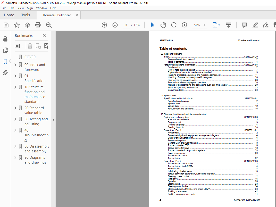
00 Index and foreword
Index SEN00205-29
Composition of shop manual 2
Table of contents 4
Foreword and general information SEN00206-05
Safety notice 2
How to read the shop manual 7
Explanation of terms for maintenance standard 9
Handling of electric equipment and hydraulic component 11
Handling of connectors newly used for engines 20
How to read electric wire code 23
Precautions when carrying out operation 26
Method of disassembling and connecting push-pull type coupler 29
Standard tightening torque table 32
Conversion table 36
01 Specification
Specification and technical data SEN00208-01
Specification drawings 2
Specifications 3
Weight table 12
Fuel, coolant and lubricants 16
10 Structure, function and maintenance standard
Engine and cooling system SEN00210-00
Radiator and oil cooler 2
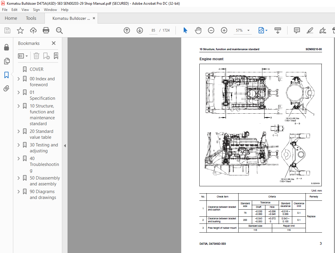
Engine mount 3
Cooling fan pump 4
Cooling fan motor 26
Power train, Part 1 SEN00211-01
Power train 2
Power train hydraulic equipment arrangement diagram 4
Damper and universal joint 6
Power train system 8
General view of power train unit 8
Torque converter, PTO 10
Torque converter valve 18
Torque converter lockup control system 28
Scavenging pump 29
Transmission control 31
Transmission 32
Power train, Part 2 SEN00212-03
Transmission control valve 2
Transmission clutch ECMV 4
Priority valve 8
Lubricating oil relief valve 10
Torque converter, power train, lubricating oil pump 11
Steering, brake control 12
Final drive 16
Sprocket 20
Steering unit 23
Steering control valve 34
Steering clutch ECMV, Steering brake ECMV 36
Parking brake valve 42
Sudden stop prevention valve 44
00 Index and foreword SEN00205-29
D475A-5E0, D475ASD-5E0 5
Undercarriage and frame SEN00213-02
Track frame 2
Recoil spring 4
Idler 6
Track roller 8
Carrier roller 12
Track roller bogie 13
Track shoe 14
Main frame 18
Suspension 20
Hydraulic system, Part 1 SEN00214-00
Work equipment hydraulic equipment arrangement diagram 2
PPC control piping diagram 6
Work equipment control 8
Work equipment pump 10
PPC valve 27
PCCS lever 38
Hydraulic system, Part 2 SEN00215-01
Control valve 2
CLSS 17
Unload valve 20
Introduction of LS pressure 21
LS bypass plug 22
Pressure compensation valve 23
Blade lift valve 26
Merge-divider valve 34
Self pressure reducing valve 36
Pilot solenoid valve 40
Hydraulic system, Part 3 SEN00216-01
Hydraulic tank, hydraulic filter 2
Accumulator 4
Work equipment cylinder 6
Piston valve 8
Quick drop valve 10
Blade control knob (Dual tilt specification) 12
Blade control knob (Superdozer specification) 13
Pitch and dual solenoid valve 14
Pin puller hydraulic circuit diagram 15
Pin puller solenoid valve 16
Work equipment SEN00217-01
Cylinder stay 2
Blade 4
Ripper equipment 8
Cab and its attachments SEN00218-00
Cab mount 2
Cab 3
Air conditioner 6
Electrical system SEN00219-03
Engine control system 2
CRI engine control system 6
Monitor system 10
Machine monitor 12
Mode selection system 30
Electrical equipment 34
Palm command control system (PCCS) 36
Sensors 38
Vehicle health monitoring system (VHMS) 45
SEN00205-29 00 Index and foreword
6 D475A-5E0, D475ASD-5E0
ORBCOMM terminal 51
20 Standard value table
Standard service value table SEN01816-01
Standard value table for engine 2
Standard value table for chassis 3
30 Testing and adjusting
Testing and adjusting, Part 1 SEN01817-03
Tools for testing, adjusting, and troubleshooting 3
Measuring engine speed 6
Measuring intake air pressure (boost pressure) 10
Measuring exhaust temperature 12
Measuring exhaust gas color 14
Adjusting valve clearance 16
Testing compression pressure 18
Measuring blow-by pressure 20
Measuring engine oil pressure 22
Handling of fuel system devices 23
Releasing residual pressure from fuel system 23
Testing fuel pressure 24
Handling of reduced cylinder mode operation 25
Handling of no injection cranking operation 25
Testing fuel return and leak amount 26
Bleeding air from fuel circuit 29
Bleeding air from fuel circuit (Low-grade fuel specification) 31
Testing fuel circuit for leakage 33
Testing and adjusting alternator belt tension 34
Testing and adjusting belt tension for air conditioner compressor 35
Adjusting fuel control dial and decelerator pedal 36
Testing and adjusting, Part 2 SEN01818-04
Measuring power train oil pressure 3
Adjusting transmission speed sensor 12
Simple method to test brake performance 13
Adjusting brake pedal and parking brake lever 14
Adjusting PCCS lever console position 17
Emergency escape method when power train has trouble 18
Inspecting wear of sprocket 20
Testing and adjusting track shoe tension 21
Testing and adjusting work equipment oil pressure 22
Testing and adjusting control circuit basic pressure 33
Measuring PPC valve output pressure and solenoid valve output pressure 34
Adjusting play of PPC valve 40
Measuring outlet pressure of ripper pin puller solenoid valve 41
Checking parts which caused hydraulic drift of blade and ripper 42
Measuring internal leakage of work equipment cylinder 43
Releasing residual pressure from work equipment cylinder 44
Bleeding air from work equipment cylinder 44
Adjusting ripper lever position 45
Adjusting work equipment lock lever 46
Measuring fan motor speed 47
Measuring fan circuit oil pressure 48
Bleeding air from fan pump 49
Measurement procedure for blade tilt control angle (Dual tiltdozer specification) 50
Measurement procedure for blade tilt control angle (Superdozer specification) 53
Testing and adjusting operator’s cab 55
Adjusting blade 59
00 Index and foreword SEN00205-29
D475A-5E0, D475ASD-5E0 7
Testing and adjusting operator’s seat isolator 61
Testing and adjusting, Part 3 SEN01819-07
Special functions of monitor panel (EMMS) 2
Testing and adjusting, Part 4 SEN01820-04
Adjustment method when controller has been replaced 2
Preparation work for troubleshooting for electrical equipment system 4
Inspection procedure of diode 8
Handling of optional devices 9
Initialization procedures for VHMS controller 10
Precautions for replacing VHMS controller 31
Pm Clinic service 36
40 Troubleshooting
Failure code table and fuse locations SEN01821-04
Failure code table 2
Fuse locations 12
General information on troubleshooting SEN01822-03
Points to remember when troubleshooting 2
Sequence of events in troubleshooting 3
Checks before troubleshooting 4
Classification and procedures of troubleshooting 5
Contents of troubleshooting table 8
Connection table for connector pin numbers 10
T- branch box and T- branch adapter table 46
Troubleshooting by failure code, Part 1 SEN01823-03
Failure code [1380MW] Lockup clutch: Clutch slip 3
Failure code [1500L0] Transmission clutch: Dual engagement 4
Failure code [15E0MW] Transmission clutch: Clutch slip 5
Failure code [15SAL1] Forward clutch oil pressure:
Command current OFF and fill signal ON 6
Failure code [15SALH] Forward clutch oil pressure:
Command current ON and fill signal OFF 7
Failure code [15SBL1] Reverse clutch: Command current OFF and fill signal ON 8
Failure code [15SBLH] Reverse clutch oil pressure:
Command current ON and fill signal OFF 9
Failure code [15SEL1] 1st clutch oil pressure: Command current OFF and fill signal ON 10
Failure code [15SELH] 1st clutch oil pressure: Command current ON and fill signal OFF 11
Failure code [15SFL1] 2nd clutch oil pressure: Command current OFF and fill signal ON 12
Failure code [15SFLH] 2nd clutch oil pressure: Command current ON and fill signal OFF 13
Failure code [15SGL1] 3rd clutch oil pressure: Command current OFF and fill signal ON 14
Failure code [15SGLH] 3rd clutch oil pressure: Command current ON and fill signal OFF 15
Failure code [1800MW] Power train clutch: Slip 16
Failure code [2201L1] Right clutch oil pressure: Command current OFF and fill signal ON 17
Failure code [2201LH] Right clutch oil pressure: Command current ON and fill signal OFF 18
Failure code [2202L1] Left clutch oil pressure: Command current OFF and fill signal ON 19
Failure code [2202LH] Left clutch oil pressure: Command current ON and fill signal OFF 20
Failure code [2300NR] Brake thermal load: Abnormal heating 21
Failure code [2301L1] Right brake oil pressure: Command current OFF and fill signal ON 22
Failure code [2301LH] Right brake oil pressure: Command current ON and fill signal OFF 23
Failure code [2301NR] Right steering brake thermal load: Abnormal heating 24
Failure code [2302L1] Left brake oil pressure: Command current OFF and fill signal ON 25
Failure code [2302LH] Left brake oil pressure: Command current ON and fill signal OFF 26
Failure code [2302NR] Left steering brake thermal load: Abnormal heating 27
Failure code [6001ZK] Failure code for design 28
Failure code [A000NS] Engine: Overheat 29
Failure code [AA10NX] Air cleaner: Clogging 30
Failure code [AB00MA] Battery charge abnormality: Malfunction 31
SEN00205-29 00 Index and foreword
8 D475A-5E0, D475ASD-5E0
Failure code [B@BAZG] Engine oil: Oil pressure too low 32
Failure code [B@BAZK] Engine oil: Oil level reduction 33
Failure code [B@BCNS] Engine coolant: Overheat 34
Failure code [B@BCZK] Engine coolant: Level too low 35
Failure code [B@BEBF] Fuel: Water in fuel 36
Failure code [B@BFZK] Fuel level: Reduction 37
Failure code [B@CENS] Power train oil: Overheat 38
Failure code [B@CHZG] HSS charge oil pressure: Low oil pressure 39
Failure code [B@CHZK] Power train oil: Oil level reduction 39
Failure code [B@GAZK] Battery electrolyte level: Electrolyte level reduction 40
Failure code [B@HANS] Hydraulic oil: Overheat 40
Failure code [B@HAZK] Hydraulic oil: Level reduction 41
Troubleshooting by failure code, Part 2 SEN01824-01
Failure code [CA111] Engine controller (Left bank): Internal abnormality 4
Failure code [CB111] Engine controller (Right bank): Internal abnormality 6
Failure code [CA115] Abnormal engine Ne and Bkup speed sensors (At left bank):
Abnormal speed sensor signal 8
Failure code [CB115] Abnormal engine Ne and Bkup speed sensors (At right bank):
Abnormal speed sensor signal 9
Failure code [CA122] Charge pressure sensor too high (At left bank only):
Excessively high voltage detected 10
Failure code [CA123] Charge pressure sensor too low (At left bank only):
Excessively low voltage detected 12
Failure code [CA131] Decelerator pedal sensor abnormally high level (Only left bank):
High voltage detection 13
Failure code [CA132] Decelerator pedal sensor too low (At left bank only):
Excessively low voltage detected 15
Failure code [CA135] Oil pressure sensor too high (At left bank only):
Excessively high voltage detected 16
Failure code [CA141] Oil pressure sensor too low (At left bank only):
Excessively low voltage detected 18
Failure code [CA144] Coolant temperature sensor too high:
Excessively high voltage detected 20
Failure code [CA145] Coolant temperature sensor too low (At left bank only):
Excessively low voltage detected 22
Failure code [CA153] Charge temperature sensor too high (At left bank only):
Excessively high voltage detected 24
Failure code [CA154] Charge temperature sensor too low (At left bank only):
Excessively low voltage detected 26
Failure code [CA187] Sensor power supply (2) abnormally low level (Left bank):
Low voltage detection 28
Failure code [CB187] Sensor power supply (2) abnormally low level (Right bank):
Low voltage detection 29
Failure code [CA212] Engine oil temperature sensor abnormally high level (Only left bank):
High voltage detection 30
Failure code [CA213] Engine oil temperature sensor abnormally low level (Only left bank):
Low voltage detection 31
Failure code [CA221] Atmospheric pressure sensor too high (At left bank only):
Excessively high voltage detected 32
Failure code [CA222] Atmospheric pressure sensor too low (At left bank only):
Excessively low voltage detected 34
Failure code [CA227] Sensor power source (2) too high (At left bank):
Excessively high voltage detected 36
Failure code [CB227] Sensor power supply (2) abnormally high level (Right bank):
High voltage detection 38
Failure code [CA234] Engine over speed (At left bank only): Excessively high speed 40
Failure code [CA238] Abnormal power source for Ne speed sensor (At left bank only):
Excessively low voltage detected 42
00 Index and foreword SEN00205-29
D475A-5E0, D475ASD-5E0 9
Failure code [CB238] Abnormal power source for Ne speed sensor (At right bank only):
Excessively low voltage detected 44
Failure code [CA263] Fuel temperature sensor too high (At left bank):
Excessively high voltage detected 46
Failure code [CB263] Fuel temperature sensor too high (At right bank):
Excessively high voltage detected 48
Failure code [CA265] Fuel temperature sensor abnormally low level (Left bank):
Low voltage detection 49
Failure code [CB265] Fuel temperature sensor abnormally low level (Right bank):
Low voltage detection 49
Failure code [CA271] PCV1 short circuit (Left bank): Short circuit 50
Failure code [CB271] PCV1 short circuit (Right bank): Short circuit 51
Failure code [CA272] PCV1 disconnection (Left bank): Disconnection 52
Failure code [CB272] PCV1 disconnection (Right bank): Disconnection 53
Failure code [CA273] PCV2 short circuit (Left bank): Short circuit 54
Failure code [CB273] PCV2 short circuit (Right bank): Short circuit 55
Failure code [CA274] PCV2 disconnection (Left bank): Disconnection 56
Failure code [CB274] PCV2 disconnection (Right bank): Disconnection 57
Troubleshooting by failure code, Part 3 SEN01825-03
Failure code [CA322] Injector #1 (L/B #1) system disconnection or short circuit
(At left bank): Disconnection, short circuit 4
Failure code [CA323] Injector #5 (L/B #5) system disconnection or short circuit
(At left bank): Disconnection, short circuit 6
Failure code [CA324] Injector #3 (L/B #3) system disconnection or short circuit
(At left bank): Disconnection, short circuit 8
Failure code [CA325] Injector #6 (L/B #6) system disconnection or short circuit
(At left bank): Disconnection, short circuit 10
Failure code [CA331] Injector #2 (L/B #2) system disconnection or short circuit
(At left bank): Disconnection, short circuit 12
Failure code [CA332] Injector #4 (L/B #4) system disconnection or short circuit
(At left bank): Disconnection, short circuit 14
Failure code [CA342] Engine controller data mismatch (Left bank): Mismatch 16
Failure code [CB342] Engine controller data mismatch (Right bank): Mismatch 17
Failure code [CA351] Abnormal injector drive circuit (At left bank): Abnormal circuit 18
Failure code [CB351] Injector drive circuit abnormality (Right bank): Circuit abnormality 20
Failure code [CA352] Sensor power supply (1) abnormally low level (Left bank):
Low voltage detection 22
Failure code [CB352] Sensor power supply (1) abnormally low level (Right bank):
Low voltage detection 23
Failure code [CA386] Sensor power supply (1) abnormally high level (Left bank):
High voltage detection 24
Failure code [CB386] Sensor power supply (1) abnormally high level (Right bank):
High voltage detection 26
Failure code [CA441] Power supply voltage abnormally low level (Left bank):
Low voltage detection 28
Failure code [CB441] Power supply voltage abnormally low level (Right bank):
Low voltage detection 28
Failure code [CA442] Power supply voltage abnormally high level (Left bank):
High voltage detection 29
Failure code [CB442] Power supply voltage abnormally high level (Right bank):
High voltage detection 29
Failure code [CA449] Common rail abnormally high pressure (2) (Left bank):
Abnormally high pressure occurrence 30
Failure code [CB449] Common rail abnormally high pressure (2) (Right bank):
Abnormally high pressure occurrence 30
Failure code [CA451] Common rail pressure sensor too high (At left bank):
Excessively high voltage detected 32
SEN00205-29 00 Index and foreword
10 D475A-5E0, D475ASD-5E0
Failure code [CB451] Common rail pressure sensor abnormally high level (Right bank):
High voltage detection 34
Failure code [CA452] Common rail pressure sensor abnormally low level (Left bank):
Abnormally low voltage detection 36
Failure code [CB452] Common rail pressure sensor abnormally low level (Right bank):
Abnormally low voltage detection 36
Failure code [CA553] Common rail pressure too high (1) (At left bank):
Excessively high pressure detected 37
Failure code [CB553] Common rail pressure too high (1) (At right bank):
Excessively high pressure detected 38
Failure code [CA554] In-range error in common rail pressure sensor (At left bank):
In-range error 39
Failure code [CB554] In-range error in common rail pressure sensor (At right bank):
In-range error 39
Failure code [CA559] Loss of pressure feed from supply pump (1) (At left bank):
Loss of pressure feed detected 40
Failure code [CA559] Loss of pressure feed from supply pump (1) (At left bank):
Loss of pressure feed detected (Low-grade fuel specification) 44
Failure code [CB559] Loss of pressure feed from supply pump (1) (At right bank):
Loss of pressure feed detected 48
Failure code [CA689] Abnormal engine Ne speed sensor (At left bank): Abnormal signal 52
Failure code [CB689] Abnormal engine Ne speed sensor (At right bank): Abnormal signal 54
Failure code [CA691] Intake air temperature sensor abnormally high level
(Only left bank): High voltage detection 56
Failure code [CA692] Intake air temperature sensor abnormally low level
(Only left bank): Low voltage detection 58
Failure code [CA731] Abnormal engine Bkup speed sensor phase (At left bank):
Abnormal phase 59
Failure code [CB731] Abnormal engine Bkup speed sensor phase (At right bank):
Abnormal phase 59
Troubleshooting by failure code, Part 4 SEN01826-01
Failure code [CA757] Loss of all engine controller data (At left bank): Loss of all data 3
Failure code [CB757] Loss of all engine controller data (At right bank): Loss of all data 3
Failure code [CA778] Abnormal engine Bkup speed sensor (At left bank):
Abnormal Bkup signal 4
Failure code [CB778] Engine Bkup speed sensor abnormality (Right bank):
Bkup signal error 6
Failure code [CA781] Inter-multicontroller communication error (Left bank):
Communication error 8
Failure code [CB781] Inter-multicontroller communication error (Right bank):
Communication error 10
Failure code [CA1257] Multicontroller distinction wiring harness key error (Left bank):
Distinction error 11
Failure code [CB1257] Multicontroller distinction wiring harness key error (Right bank):
Distinction error 12
Failure code [CB1548] Injector #7 (R/B #1) system disconnection/short circuit
(Right bank): Disconnection/Short circuit 14
Failure code [CB1549] Injector #8 (R/B #2) system disconnection/short circuit
(Right bank): Disconnection/Short circuit 16
Failure code [CB1551] Injector #10 (R/B #4) system disconnection/short circuit
(Right bank): Disconnection/Short circuit 18
Failure code [CB1552] Injector #11 (R/B #5) system disconnection/short circuit
(Right bank): Disconnection/Short circuit 20
Failure code [CB1553] Injector #12 (R/B #6) system disconnection/short circuit
(Right bank): Disconnection/Short circuit 22
Failure code [CB1622] Injector #9 (R/B #3) system disconnection/short circuit
(Right bank): Disconnection/Short circuit 24
Failure code [CA1633] KOMNET abnormality (Left bank): Communication error 26
00 Index and foreword SEN00205-29
D475A-5E0, D475ASD-5E0 11
Failure code [CA2185] Decelerator pedal sensor power supply abnormally high level
(Only left bank): High voltage detection 28
Failure code [CA2186] Decelerator pedal sensor power source too low
(At left bank only): Excessively low voltage detected 30
Failure code [CA2249] Loss of pressure feed from supply pump (2) (At left bank):
Loss of pressure feed detected 31
Failure code [CB2249] Loss of pressure feed from supply pump (2) (At right bank):
Loss of pressure feed detected 31
Failure code [D110KA] Battery relay: Disconnection 32
Failure code [D110KB] Battery relay: Short circuit 34
Failure code [D130KA] Neutral safety relay: Disconnection 36
Failure code [D130KB] Neutral safety relay: Short circuit 38
Failure code [D161KA] Back-up alarm relay: Disconnection 40
Failure code [D161KB] Back-up alarm relay: Short circuit 42
Failure code [D182KZ] Preheater relay: Disconnection or short circuit 44
Failure code [D190KA] Engine controller ACC signal cutout relay: Disconnection 46
Failure code [D190KB] Engine controller ACC signal cutout relay: Short circuit 48
Failure code [D5ZRKA] Snap shot switch: Disconnection 50
Failure code [D5ZRKB] Snap shot switch: Short circuit 51
Failure code [DAFRKR] Monitor panel CAN communication: Communication error 52
Failure code [dAFRKR] Monitor panel CAN communication: Communication error 54
Failure code [daFRKR] Monitor panel CAN communication: Communication error 56
Failure code [DAQ0KT] Transmission controller: Abnormality in controller 58
Failure code [DAQ1KK] Transmission controller main power supply:
Power supply voltage reduction (Input) 60
Failure code [DAQ2KK] Transmission controller load power supply:
Power supply voltage reduction (Input) 62
Failure code [DAQ5KK] Transmission controller potentiometer power supply:
Source voltage reduction (input) 64
Failure code [DAQ6KK] Transmission controller sensor power supply:
Source voltage reduction (input) 65
Failure code [DAQ7KK] Transmission controller sensor power supply:
Power supply voltage reduction (Input) 66
Failure code [DAQ9KQ] Transmission controller type collation:
Type select signal inconsistency 67
Failure code [DAQRKR] Transmission controller sensor CAN communication:
Communication error (Objective component system abnormality) 68
Failure code [DAQSKR] Transmission controller S-NET communication:
Defective communication (Abnormality in objective component system) 70
Troubleshooting by failure code, Part 5 SEN01827-04
Failure code [DB2RKR] Engine controller (Left bank) CAN communication:
Communication error 4
Failure code [dB2RKR] Engine controller (Left bank) CAN communication:
Communication error 6
Failure code [db2RKR] Engine controller (Right bank) CAN communication:
Communication error 8
Failure code [DB30KT] Steering controller: Abnormality in controller 10
Failure code [DB31KK] Steering controller main power supply:
Power supply voltage reduction (Input) 12
Failure code [DB32KK] Steering controller load power supply:
Power supply voltage reduction (Input) 14
Failure code [DB35KK] Steering controller potentiometer power supply:
Power supply voltage reduction (Input) 16
Failure code [DB36KK] Steering controller sensor power supply:
Source voltage reduction (input) 18
Failure code [DB37KK] Steering controller sensor power supply:
Source voltage reduction (input) 19
SEN00205-29 00 Index and foreword
12 D475A-5E0, D475ASD-5E0
Failure code [DB39KQ] Steering controller type selection:
Type select signal inconsistency 20
Failure code [dB3RKR] Steering controller CAN communication: Communication error 22
Failure code [DB3SKR] Steering controller S-NET communication:
Defective communication (Abnormality in objective component system) 24
Failure code [DBB0KK] (or LED of VHMS controller indicates “n9” o “01”)
VHMS controller: Lowering of source voltage 26
Failure code [DBB0KQ] (or LED of VHMS controller indicates “nF” o “11”)
Check of VHMS controller model: Disagreement of model selection 27
Failure code [DBB3KK] (or LED of VHMS controller indicates “n9” o “05”)
VHMS controller: Lowering of direct source voltage 28
Failure code [DBB5KP] (or LED of VHMS controller indicates “n9” o “04”)
VHMS sensor power supply (5 V): Lowering of output voltage 29
Failure code [DBB6KP] (or LED of VHMS controller indicates “n9” o “02”)
VHMS sensor power supply (24 V): Lowering of output voltage 30
Failure code [DBB7KP] (or LED of VHMS controller indicates “n9” o “03”)
VHMS sensor power supply (12 V): Lowering of output voltage 32
Failure code [DBBQKR] (or VHMS_LED display “n8” o “02”)
VHMS KOM-NET: Communication error 34
Failure code [dbBRKR] VHMS controller CAN communication: Communication error 36
Failure code [DD12KA] Shift up switch: Disconnection 38
Failure code [DD12KB] Shift up switch: Short circuit 40
Failure code [DD13KA] Shift down switch: Disconnection 42
Failure code [DD13KB] Shift down switch: Short circuit 44
Failure code [DD14KA] Parking brake lever switch: Disconnection 46
Failure code [DD14KB] Parking brake lever switch: Short circuit 48
Failure code [DDB9L4] Reverse switch: Signal disagreement 50
Failure code [DDK3L4] Forward switch: Signal disagreement 52
Failure code [DDK4KA] Directional switch open circuit or hot short 54
Failure code [DDK4KB] Directional switch ground fault 56
Failure code [DDK5KA] Gearshift switch: Disconnection 58
Failure code [DDK5KB] Gearshift switch: Short circuit 60
Failure code [DDN2LD] (Blade tilt right oil pressure switch system:
Switch is ON for long time 62
Failure code [DDN3LD] Blade tilt left oil pressure switch system: Switch is ON for long time 63
Failure code [DDN7KA] Blade pitch switch: Disconnection 64
Failure code [DDN7KB] Blade pitch switch: Short circuit 66
Failure code [DDN9KA] Blade tilt switch: Disconnection 68
Failure code [DDN9KB] Blade tilt switch: Short circuit 70
Failure code [DDNALD] (Blade lift raise full oil pressure switch: Switch is ON for long time 72
Failure code [DDNBLD] Ripper lift raise oil pressure switch: Switch is ON for long time 73
Failure code [DDNCLD] Ripper lift lower oil pressure switch: Switch is ON for long time 74
Failure code [DDNDLD] Ripper tilt in oil pressure switch: Switch is ON for long time 75
Failure code [DDNELD] (Ripper tilt back oil pressure switch: Switch is ON for long time 76
Failure code [DDNFLD] Blade lift lower full oil pressure switch: Switch is ON for long time 77
Troubleshooting by failure code, Part 6 SEN01828-04
Failure code [DDQ2KA] Parking brake lever switch: Disconnection 4
Failure code [DDQ2KB] Parking brake lever switch: Short circuit 6
Failure code [DDQ2L4] Parking brake lever switch: Disagreement of signals 8
Failure code [dDQ2L4] Parking brake lever switch: Disagreement of signals 9
Failure code [DDT5KA] Neutral switch: Disconnection 10
Failure code [DDT5KB] Neutral switch: Short circuit 12
Failure code [DDT5KQ] Lever specification selection:
Model selection signal disagreement 14
Failure code [DGS1KX] Hydraulic oil temperature sensor:
Input signal is out of normal range 15
Failure code [DGT1KA] Power train oil temperature sensor: Disconnection 16
00 Index and foreword SEN00205-29
D475A-5E0, D475ASD-5E0 13
Failure code [DGT1KX] Power train oil temperature sensor:
Input signal is out of normal range 17
Failure code [DGT5KA] Left bank exhaust temperature sensor system (Front):
Disconnection (or LED of VHMS controller indicates “n3” o “12”) 18
Failure code [dGT5KA] Left bank exhaust temperature sensor system (Rear):
Disconnection (or LED of VHMS controller indicates “n3” o “22”) 20
Failure code [DGT5KB] Left bank exhaust temperature sensor system (Front):
Short circuit (or LED of VHMS controller indicates “n3” o “11”) 22
Failure code [dGT5KB] (or LED of VHMS controller indicates “n3” o “21”)
Left bank exhaust temperature sensor system (Rear): Short circuit 24
Failure code [DGT6KA] (or LED of VHMS controller indicates “n3” o “24”)
Right bank exhaust temperature sensor system (Front): Disconnection 26
Failure code [dGT6KA] (or LED of VHMS controller indicates “n3” o “26”)
Right bank exhaust temperature sensor system (Rear): Disconnection 28
Failure code [DGT6KB] (or LED of VHMS controller indicates “n3” o “23”)
Right bank exhaust temperature sensor system (Front): Short circuit 30
Failure code [dGT6KB] (or LED of VHMS controller indicates “n3” o “25”)
Right bank exhaust temperature sensor system (Rear): Short circuit 32
Failure code [DH22KA] Work equipment pump oil pressure sensor (F): Disconnection 34
Failure code [DH22KB] Work equipment pump oil pressure sensor (F): Short circuit 35
Failure code [DH23KA] Work equipment pump oil pressure sensor (R): Disconnection 36
Failure code [DH23KB] Work equipment pump oil pressure sensor (R): Short circuit 37
Failure code [DHE5KB] (or LED of VHMS controller indicates “n3” o “32”)
Blow-by pressure sensor system: Disconnection 38
Failure code [DHE5KY] (or LED of VHMS controller indicates “n3” o “31”)
Blow-by pressure sensor system: Hot short 39
Failure code [DHT3KX] (or LED of VHMS controller indicates “n6” o “14”)
Transmission oil pressure sensor: Out of input signal range 40
Failure code [DK01KA] Left yoke angle sensor: Disconnection 41
Failure code [DK01KB] Left yoke angle sensor: Short circuit 42
Failure code [DK03KA] Right yoke angle sensor: Disconnection 43
Failure code [DK03KB] Right yoke angle sensor: Short circuit 44
Failure code [DK10KA] Fuel dial: Disconnection 45
Failure code [DK10KB] Fuel dial: Short circuit 46
Failure code [DK30KA] Steering potentiometer (1): Disconnection 48
Failure code [DK30KB] Steering potentiometer (1): Short circuit 50
Failure code [DK30KX] Steering potentiometer (1): Input signal is out of normal range 52
Failure code [DK30KZ] Steering potentiometer (1): Disconnection or short circuit 52
Failure code [DK30L8] Steering potentiometer (1): See table 53
Failure code [DK31KA] Steering potentiometer (2): Disconnection 54
Failure code [DK31KB] Steering potentiometer (2): Short circuit 56
Troubleshooting by failure code (Display of code), Part 7 SEN01829-03
Failure code [DK40KA] Brake potentiometer: Disconnection 3
Failure code [DK40KB] Brake potentiometer: Short circuit 4
Failure code [DK55KX] Forward-reverse potentiometer: Input signal is out of normal range 5
Failure code [DK55KZ] Forward-reverse potentiometer: Disconnection or short circuit 6
Failure code [DK55L8] Forward-reverse potentiometer: See table 7
Failure code [DK56KA] Forward-reverse potentiometer (1): Disconnection 8
Failure code [DK56KB] Forward-Reverse potentiometer (1): Short circuit 10
Failure code [DK57KA] Forward-reverse potentiometer (2): Disconnection 12
Failure code [DK57KB] Forward-Reverse potentiometer (2): Short circuit 14
Failure code [DK60KA] Acceleration sensor: Disconnection 16
Failure code [DK60KB] Acceleration sensor: Short circuit 18
Failure code [DKH1KA] Pitch angle sensor: disconnection 19
Failure code [DKH1KB] Pitch angle sensor: Short circuit 20
Failure code [DKH1KX] Pitch angle sensor: Out of input signal range 21
Failure code [DKW0KX] Swing RIGHT lever potentiometer: Out of input signal range 22
Failure code [DKW0KZ] Swing RIGHT lever potentiometer: Open circuit or short circuit 22
SEN00205-29 00 Index and foreword
14 D475A-5E0, D475ASD-5E0
Failure code [DKW0L8] Swing RIGHT lever potentiometer: Analog signals are inconsistent 23
Failure code [DKW1KA] Swing RIGHT lever potentiometer 2: Open circuit 24
Failure code [DKW1KB] Swing RIGHT lever potentiometer 2: short circuit 26
Failure code [DKW2KA] Swing RIGHT lever potentiometer 2: Open circuit 28
Failure code [DKW2KB] Swing RIGHT lever potentiometer 2: short circuit 30
Failure code [DKW3KX] Swing LEFT lever potentiometer: Out of input signal range 32
Failure code [DKW3KZ] Swing LEFT lever potentiometer: Open circuit or short circuit 32
Failure code [DKW3L8] Swing LEFT lever potentiometer: Analog signal inconsistency 33
Failure code [DKW4KA] Swing LEFT lever potentiometer 1: Open circuit 34
Failure code [DKW4KB] Swing LEFT lever potentiometer 1: Short circuit 36
Failure code [DKW5KA] Swing LEFT lever potentiometer 2: Open circuit 38
Failure code [DKW5KB] Swing LEFT lever potentiometer 2: Short circuit 40
Failure code [DLF1KA] Torque converter output speed sensor: Disconnection 42
Failure code [DLT3KA] Transmission output speed sensor: Disconnection 43
Failure code [dLT3KA] Transmission output speed sensor: Disconnection 44
Failure code [DLT3KB] Transmission output speed sensor: Short circuit 46
Failure code [DV00KB] Caution buzzer: Short circuit 47
Failure code [DW55KA] Blade pitch back solenoid: Disconnection 48
Failure code [DW55KB] Blade pitch back solenoid: Short circuit 49
Failure code [DW56KA] Blade pitch dump solenoid: Disconnection 50
Failure code [DW56KB] Blade pitch dump solenoid: Short circuit 51
Failure code [DW56KY] Blade pitch dump solenoid: Hot short 52
Failure code [DW57KA] Left tilt limit solenoid: Disconnection 53
Failure code [DW57KB] Left tilt limit solenoid: Short circuit 54
Failure code [DW57KY] Left tilt limit solenoid: Hot short 55
Failure code [DW58KA] Right tilt limit solenoid: Disconnection 56
Failure code [DW58KB] Right tilt limit solenoid: Short circuit 57
Failure code [DW58KY] Right tilt limit solenoid: Hot short 58
Failure code [DW59KA] Dual tilt selector solenoid: Disconnection 59
Failure code [DW59KB] Dual tilt selector solenoid: Short circuit 60
Failure code [DW59KY] Dual tilt selector solenoid: Hot short 61
Failure code [DW5AKA] Blade pitch selector solenoid: Disconnection 62
Failure code [DW5AKB] Blade pitch selector solenoid: Short circuit 63
Failure code [DW5AKY] Blade pitch selector solenoid: Hot short 64
Failure code [DW5DKA] Blade pitch selector solenoid (superdozer specification):
Disconnection 65
Failure code [DW5DKB] Blade pitch selector solenoid (Superdozer specification):
Short circuit 66
Failure code [DW5DKY] Blade pitch selector solenoid (Superdozer specification):
Hot short 67
Failure code [DW7BKA] Fan reverse solenoid: Disconnection 68
Failure code [DW7BKB] Fan reverse solenoid: Short circuit 69
Failure code [DW7BKY] Fan reverse solenoid: Hot short 70
Failure code [DWJ0KA] Pump merge-divider solenoid: Disconnection 71
Failure code [DWJ0KB] Pump merge-divider solenoid: Short circuit 72
Failure code [DWJ0KY] Pump merge-divider solenoid: Hot short 73
Failure code [DWN3KA] Sudden stop prevention solenoid: Disconnection 74
Failure code [DWN3KB] Sudden stop prevention solenoid: Short circuit 75
Failure code [DWN3KY] Sudden stop prevention solenoid: Hot short 76
Failure code [DWN5KA] Fan pump solenoid 1: Disconnection 77
Failure code [DWN5KB] Fan pump solenoid 1: Short circuit 78
Failure code [DWN5KY] Fan pump solenoid 1: Hot short 79
Failure code [DWNCKA] Fan pump solenoid 2: Disconnection 80
Failure code [DWNCKB] Fan pump solenoid 2: Short circuit 81
Failure code [DWNCKY] Fan pump solenoid 2: Hot short 82
Troubleshooting by failure code (Display of code), Part 8 SEN01830-01
Failure code [DXE0KA] LS set solenoid: Disconnection 3
Failure code [DXE0KB] LS set solenoid: Short circuit 4
00 Index and foreword SEN00205-29
D475A-5E0, D475ASD-5E0 15
Failure code [DXE0KY] LS set solenoid: Hot short 5
Failure code [DXH1KA] Lock-up solenoid: Disconnection 6
Failure code [DXH1KB] Lock-up solenoid: Short circuit 7
Failure code [DXH1KY] Lockup solenoid: Hot short 8
Failure code [DXH4KA] 1st clutch ECMV: Disconnection 9
Failure code [DXH4KB] 1st clutch ECMV: Short circuit 10
Failure code [DXH4KY] 1st clutch ECMV: Hot short 11
Failure code [DXH5KA] 2nd clutch ECMV: Disconnection 12
Failure code [DXH5KB] 2nd clutch ECMV: Short circuit 13
Failure code [DXH5KY] 2nd clutch ECMV: Hot short 14
Failure code [DXH6KA] 3rd clutch ECMV: Disconnection 15
Failure code [DXH6KB] 3rd clutch ECMV: Short circuit 16
Failure code [DXH6KY] 3rd clutch ECMV: Hot short 17
Failure code [DXH7KA] Reverse clutch ECMV: Disconnection 18
Failure code [DXH7KB] Reverse clutch ECMV: Short circuit 19
Failure code [DXH7KY] Reverse clutch ECMV: Hot short 20
Failure code [DXH8KA] Forward clutch ECMV: Disconnection 21
Failure code [DXH8KB] Forward clutch ECMV: Short circuit 22
Failure code [DXH8KY] Forward clutch ECMV: Hot short 23
Failure code [DXH9KA] Right steering clutch ECMV: Disconnection 24
Failure code [DXH9KB] Right steering clutch ECMV: Short circuit 25
Failure code [DXH9KY] Right steering clutch ECMV: Hot short 26
Failure code [DXHAKA] Left steering clutch ECMV: Disconnection 27
Failure code [DXHAKB] Left steering clutch ECMV: Short circuit 28
Failure code [DXHAKY] Left steering clutch ECMV: Hot short 29
Failure code [DXHBKA] Right brake ECMV: Disconnection 30
Failure code [DXHBKB] Right brake ECMV: Short circuit 31
Failure code [DXHBKY] Right brake ECMV: Hot short 32
Failure code [DXHCKA] Left brake ECMV: Disconnection 33
Failure code [DXHCKB] Left brake ECMV: Short circuit 34
Failure code [DXHCKY] Left brake ECMV: Hot short 35
Failure code [F@BBZL] (or VHMS_LED display “n3” o “38”)
Engine blow-by pressure sensor: Abnormally high pressure occurrence 36
Failure code [F@BYNS] (or VHMS_LED display “n3” o “61”)
Left front exhaust temperature sensor (1): Exhaust temperature abnormal rise 38
Failure code [f@BYNS] (or VHMS_LED display “n3” o “71”)
Left rear exhaust temperature sensor (1): Exhaust temperature abnormal rise 40
Failure code [F@BZNS] (or VHMS_LED display “n3” o “38”)
Right front exhaust temperature sensor (1): Exhaust temperature abnormal rise 42
Failure code [f@BZNS] (or VHMS_LED display “n3” o “39”)
Right rear exhaust temperature sensor (1): Exhaust temperature abnormal rise 44
Failure code [F@BYNR] (or VHMS_LED display “n3” o “62”)
Left front exhaust temperature sensor (2): Exhaust temperature abnormal rise 46
Failure code [f@BYNR] (or VHMS_LED display “n3” o “72”)
Left rear exhaust temperature sensor (2): Exhaust temperature abnormal rise 48
Failure code [F@BZNR] (or VHMS_LED display “n3” o “82”)
Right front exhaust temperature sensor (2): Exhaust temperature abnormal rise 50
Failure code [f@BZNR] (or VHMS_LED display “n3” o “92”)
Right rear exhaust temperature sensor (2): Exhaust temperature abnormal rise 52
Troubleshooting of electrical system (E-mode) SEN01831-03
Contents of troubleshooting table 3
E-1 The engine does not start 4
E-2 The preheater does not operate 8
E-3 The ripper pin puller cylinder does not operate 12
E-4 The monitor panel does not come on at all when the starting switch is turned on 14
E-5 When the starting switch is turned on, the monitor panel completely remains lighted
and does not go out 16
E-6 When the starting switch is turned on, the basic check items flash 17
SEN00205-29 00 Index and foreword
16 D475A-5E0, D475ASD-5E0
E-7 While the engine is operating, any caution item flashes 18
E-8 An emergency caution item flashes while the engine is running 21
E-9 While the preheater is operating, the preheating pilot lamp does not come on 24
E-10 At the selecting time of dual tilt, the dual/single tilt selector lamp does not come on
(Dual tilt-mounted machine) 26
E-11 At the locking-up of the torque converter, the torque converter lock-up display lamp
does not come on 26
E-12 The engine coolant temperature gauge does not indicate normally 27
E-13 Indication of the power train (torque converter) temperature gauge is abnormal 28
E-14 The hydraulic oil temperature gauge does not indicate normally 30
E-15 Indication of the fuel gauge is abnormal 31
E-16 Indications of gear speed and engine speed are abnormal 32
E-17 Indication of the shift mode service meter is abnormal 32
E-18 The switch module cannot be operated 33
E-19 The warning lamp does not flash or does not go out 34
E-20 The alarm buzzer does not sound or does not stop 35
E-21 Auto shift down is not possible or is not released 36
E-22 The automatic pitch back system does not operate (only superdozer specification) 37
E-23 The alarm buzzer cannot be cancelled 38
E-24 The operator mode cannot be operated 39
E-25 The service mode cannot be operated 40
E-26 The back-up alarm does not sound 42
E-27 The night light, the headlamp, the working lamp and the rear lamp on the panel
do not come on 44
E-28 Troubleshooting for air conditioner system 50
E-29 Orbcomm terminal does not operate normally (Data are not transmitted) 65
E-30 Fan does not reverse 67
E-31 Gear cannot be shifted 69
E-32 Electric priming pump does not operate or does not stop automatically 70
E-33 Engine pre-lube system does not operate 72
Troubleshooting of hydraulic and mechanical system (H-mode) SEN01832-02
Information in troubleshooting table 3
H-1 No force (no drawbar pull) 4
H-2 No travel (at 2nd or 3rd speed) 6
H-3 No travel at all gear speeds 7
H-4 Machine travels only in one direction forward or in reverse 8
H-5 Large time lag at gear speed shifting or forward-reverse shifting 9
H-6 Steering is not possible 10
H-7 Steering is possible only on one side 11
H-8 Steering overrun occurs 12
H-9 Brake does not work 13
H-10 Torque converter is not lock-up 14
H-11 Power train oil is overheated 15
H-12 All work equipment speeds are slow 16
H-13 Work equipment does not move 17
H-14 Blade lift speed is slow or lacks power 18
H-15 Blade tilt speed is slow or lacks power 19
H-16 Ripper lift speed is slow or lacks power 20
H-17 Ripper tilt speed is slow or lacks power 21
H-18 Excessive hydraulic drift of blade lift 22
H-19 Excessive hydraulic drift of blade tilt 23
H-20 Excessive hydraulic drift of ripper lift 24
H-21 Ripper pin puller cylinder does not work (giant ripper attachment machine) 24
H-22 Blade pitch does not work (dual tilt attachment machine) 25
H-23 Abnormal sound comes out from around work equipment pump 25
H-24 Fan speed is abnormal (Sound and/or vibration of fan are/is abnormally large or
engine overheats) 26
00 Index and foreword SEN00205-29
D475A-5E0, D475ASD-5E0 17
H-25 Operator’s seat isolator quakes abnormally or makes shocks (Machine with
operator’s seat isolator) 27
Troubleshooting of engine (S-mode) SEN01833-01
Method of using troubleshooting chart 3
S-1 Starting performance is poor 6
S-2 Engine does not start 7
S-3 Engine does not pick up smoothly 10
S-4 Engine stops during operations 11
S-5 Engine does not rotate smoothly 12
S-6 Engine lacks output (or lacks power) 13
S-7 Exhaust smoke is black (incomplete combustion) 15
S-8 Oil consumption is excessive (or exhaust smoke is blue) 16
S-9 Oil becomes contaminated quickly 17
S-10 Fuel consumption is excessive 18
S-11 Oil is in coolant (or coolant spurts back or coolant level goes down) 19
S-12 Oil pressure drops 20
S-13 Oil level rises (Entry of coolant or fuel) 21
S-14 Coolant temperature becomes too high (overheating) 22
S-15 Abnormal noise is made 23
S-16 Vibration is excessive 24
50 Disassembly and assembly
General information on disassembly and assembly SEN02013-08
How to read this manual 2
Coating materials list 4
Special tools list 7
Sketches of special tools 17
Engine and cooling system (SAA12V140E-3) SEN02014-03
Removal and installation of engine assembly 2
Removal and installation of radiator assembly 6
Removal and installation of aftercooler assembly 8
Removal and installation of radiator guard assembly 10
Removal and installation of fuel tank assembly 12
Removal and installation of engine hood assembly 13
Removal and installation of fan drive assembly 15
Removal and installation of fan motor assembly 16
Engine (SAA12V140E-3) SEN02338-05
Removal and installation of fuel supply pump assembly 2
Removal and installation of cylinder head assembly 8
Removal and installation of fuel injector assembly 19
Removal and installation of engine front seal 25
Removal and installation of engine rear seal 27
Power train, Part 1 SEN02015-04
Removal and installation of damper assembly 2
Disassembly and assembly of damper assembly 4
Removal and installation of power train unit assembly 7
Removal and installation of PTO, torque converter assembly 11
Disconnection and connection of PTO, torque converter assembly 13
Disassembly and assembly of torque converter assembly 15
Disassembly and assembly of PTO assembly 25
Removal and installation of TORQFLOW transmission assembly 32
Disassembly and assembly of TORQFLOW transmission assembly 33
Power train, Part 2 SEN02016-07
Disassembly and assembly of steering case assembly 2
Disassembly and assembly of steering clutch, brake assembly 14
Disassembly and assembly of transfer gear housing assembly 21
Removal and installation of power train pump assembly 25
SEN00205-29 00 Index and foreword
18 D475A-5E0, D475ASD-5E0
Removal and installation of scavenging pump assembly 25
Removal and installation of torque converter oil cooler 26
Removal and installation of torque converter valve assembly 27
Disassembly and assembly of torque converter valve assembly 28
Removal and installation of transmission control valve assembly 32
Disassembly and assembly of transmission control valve assembly (ECMV assembly) 33
Removal and installation of steering control valve assembly 36
Disassembly and assembly of steering control valve assembly 37
Removal and installation of final drive assembly 39
Disassemble and assemble final drive assembly 41
Undercarriage and frame, Part 1 SEN02017-09
Removal and installation of track frame assembly 2
Disassembly and assembly of idler assembly 5
Removal and installation of recoil spring assembly 8
Disassembly and assembly of recoil spring assembly 20
Removal and installation of track roller assembly 22
Disassembly and assembly of track roller assembly 24
Removal and installation of carrier roller assembly 26
Disassembly and assembly of carrier roller assembly 27
Removal and installation of bogie assembly 30
Disassembly and assembly of bogie assembly 34
Removal and installation of No 1 bogie assembly 36
Removal and installation of operator’s seat isolator 41
Disassembly and assembly of operator’s seat isolator 42
Undercarriage and frame, Part 2 SEN02018-06
Expansion and installation of track shoe assembly 2
Overall disassembly and overall assembly of track shoe 5
Press-fitting jig dimension table for link press 20
Field disassembly and assembly of one link 21
Disassembly and assembly of master link 26
Removal and installation of pivot shaft assembly 32
Removal and installation of equalizer bar 34
Disassembly and assembly of equalizer bar bushing 37
Hydraulic system SEN02019-05
Removal and installation of hydraulic pump assembly 2
Removal and installation of hydraulic valve assembly 4
Disassembly and assembly of control valve 5
Disassembly and assembly of merge divider valve and self pressure reducing valve assembly 9
Removal and installation of PPC relief valve assembly 11
Disassembly and assembly of hydraulic cylinder assembly 12
Disassembly and assembly of ripper pin puller cylinder assembly 17
Remove and install blade lift cylinder assembly 20
Work equipment SEN02020-03
Removal and installation of blade assembly 2
Disassembly and assembly of giant ripper assembly 4
Cab and its attachments SEN02021-03
Removal and installation of ROPS guard 2
Removal and installation of operator’s cab assembly 3
Removal and installation of floor frame assembly 4
Electrical system SEN02339-04
Removal and installation of controller assembly 2
Removal and installation of engine controller assembly (left) 3
Removal and installation of air conditioner condenser assembly 4
Removal and installation of air conditioner compressor assembly 5
Removal and installation of air conditioner unit 7
00 Index and foreword SEN00205-29
D475A-5E0, D475ASD-5E0 19
90 Diagrams and drawings
Hydraulic diagrams and drawings SEN00225-00
Power train hydraulic circuit diagram 3
Hydraulic circuit diagram (1/3) 5
Hydraulic circuit diagram (2/3) 7
Hydraulic circuit diagram (3/3) 9
Electrical diagrams and drawings SEN00226-05
Electrical circuit diagram (1/17) 3
Electrical circuit diagram (2/17) 5
Electrical circuit diagram (3/17) 7
Electrical circuit diagram (4/17) 9
Electrical circuit diagram (5/17) 11
Electrical circuit diagram (6/17) 13
Electrical circuit diagram (7/17) 15
Electrical circuit diagram (8/17) 17
Electrical circuit diagram (9/17) 19
Electrical circuit diagram (10/17) 21
Electrical circuit diagram (11/17) 23
Electrical circuit diagram (12/17) 25
Electrical circuit diagram (13/17) 27
Electrical circuit diagram (14/17) 29
Electrical circuit diagram (15/17) 31
Electrical circuit diagram (16/17) 33
Electrical circuit diagram (17/17) 35
Electrical circuit diagram of inside cab (1/3) 37
Electrical circuit diagram of inside cab (2/3) 39
Electrical circuit diagram of inside cab (3/3) 41
Connector arrangement diagram 43
IMAGES PREVIEW OF THE MANUAL:
More products