$37
Komatsu Galeo PC1800-6 Hydraulic Excavator Field Assembly Instruction Manual SEAW003503 – PDF
Komatsu Galeo PC1800-6 Hydraulic Excavator Field Assembly Instruction Manual SEAW003503 – PDF DOWNLOAD
FILE DETAILS:
Komatsu Galeo PC1800-6 Hydraulic Excavator Field Assembly Instruction Manual SEAW003503 – PDF DOWNLOAD
Language : English
Pages : 289
Downloadable : Yes
File Type : PDF
Size: 78.1 MB
IMAGES PREVIEW OF THE MANUAL:
DESCRIPTION:
Komatsu Galeo PC1800-6 Hydraulic Excavator Field Assembly Instruction Manual SEAW003503 – PDF DOWNLOAD
MACHINE MODEL SERIAL No.
PC1800-6 10011,11002 and up
- The Komatsu Galeo PC1800-6 Hydraulic Excavator Field Assembly Instruction Manual (GEN00003-04) is a comprehensive guide for the assembly of the Komatsu PC1800-6 hydraulic excavator. This manual provides step-by-step instructions for the assembly of the excavator, including detailed illustrations and photographs that help to clarify each step. The manual is designed to provide information and guidance to those who are responsible for the assembly of the excavator, including technicians, mechanics, and other professionals in the construction and mining industries.
- The manual covers all aspects of the assembly process, from unpacking and preparing the components to assembling the various systems and components of the excavator. This includes the hydraulic, electrical, and mechanical systems, as well as the cab and other components. The manual provides detailed information on the tools and equipment needed for the assembly process, and includes guidelines for the proper handling and storage of the components to ensure their longevity and performance.
- In addition to providing step-by-step instructions for the assembly process, the Komatsu Galeo PC1800-6 Hydraulic Excavator Field Assembly Instruction Manual also includes important safety information, including guidelines for working with the excavator components and guidelines for working in the vicinity of the excavator. This information is crucial for ensuring that the assembly process is completed safely and that workers are protected from potential hazards.
- Overall, the Komatsu Galeo PC1800-6 Hydraulic Excavator Field Assembly Instruction Manual is an essential resource for anyone who is involved in the assembly of the Komatsu PC1800-6 hydraulic excavator. Whether you are an experienced technician or just starting out, this manual provides a wealth of information that can help you assemble the excavator quickly and efficiently, and ensure that it is assembled to the highest standards.
TABLE OF CONTENTS:
Komatsu Galeo PC1800-6 Hydraulic Excavator Field Assembly Instruction Manual SEAW003503 – PDF DOWNLOAD
COVER…………………………………………………………… 1
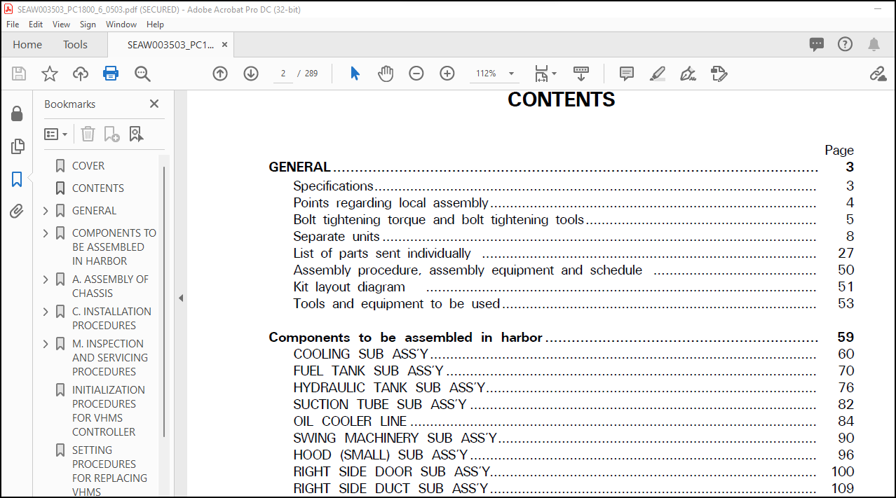
CONTENTS………………………………………………………… 2
GENERAL…………………………………………………………. 4
1. SPECIFICATIONS…………………………………………….. 4
2. POINTS REGARDING LOCAL ASSEMBLY……………………………… 5
3. BOLT TIGHTENING TORQUE AND BOLT TIGHTENING TOOLS………………. 6
4. SEPARATE UNITS…………………………………………….. 9
5. LIST OF PARTS SENT INDIVIDUALLY……………………………… 28
6. ASSEMBLY PROCEDURE, ASSEMBLY EQUIPMENT AND SCHEDULE……………. 51
7. KIT LAYOUT DIAGRAM…………………………………………. 52
8. TOOLS AND EQUIPMENT TO BE USED………………………………. 53
COMPONENTS TO BE ASSEMBLED IN HARBOR……………………………….. 60
COOLING SUB ASS’Y…………………………………………….. 61
FUEL TANK SUB ASS’Y…………………………………………… 71
HYDRAULIC TANK SUB ASS’Y………………………………………. 77
SUCTION TUBE SUB ASS’Y………………………………………… 83
OIL COOLER LINE………………………………………………. 85
SWING MACHINERY SUB ASS’Y……………………………………… 91
HOOD (SMALL) SUB ASS’Y………………………………………… 97
RIGHT SIDE DOOR SUB ASS’Y………………………………………101
RIGHT SIDE DUCT SUB ASS’Y………………………………………110
PARTITION COVER……………………………………………….112
MUFFLER COVER…………………………………………………114
BATTERY CASE SUB ASS’Y…………………………………………116
A. ASSEMBLY OF CHASSIS…………………………………………….121
A-1: ASSEMBLY OF TRACK FRAME AND AXLE……………………………122
A-2: TRAVEL MOTOR PIPING……………………………………….125
A-3: IDLER CUSHION CYLINDER PIPING………………………………127
A-4: INSTALLATION OF TRAVEL MOTOR GUARD………………………….128
A-5: FILLING SWING CIRCLE WITH GREASE……………………………130
A-6: ASSEMBLY OF REVOLVING FRAME ASSEMBLY AND AXLE ASSEMBLY………..131
A-7: SWIVEL TRAVEL PIPING………………………………………133
A-8: SWING CIRCLE GREASE TUBE PIPING…………………………….135
A-9: INSTALLATION OF LEFT AND RIGHT LADDERS………………………143
A-10: INSTALLATION OF LEFT CATWALK (STD)…………………………144
A-11: INSTALLATION OF RIGHT CATWALK……………………………..145
A-12: INSTALLATION OF CATWALK, HANDRAIL BESIDE OPERATOR’S CAB………146
A-13: INSTALLATION OF OPERATOR’S CAB LADDER………………………147
A-14: INSTALLATION OF OPERATOR’S CAB HANDRAIL…………………….148
A-16: INSTALLATION OF HANDRAIL AT REAR OF OPERATOR’S CAB…………..149
A-18: OPERATOR’S CAB FRONT FRAME, HANDRAIL……………………….150
A-20: RIGHT DECK HANDRAIL………………………………………151
A-21: INSTALLATION OF LADDER ON TOP OF HYDRAULIC TANK……………..152
A-22: INSTALLATION OF COUNTERWEIGHT……………………………..153
A-23: INSTALLATION OF COUNTERWEIGHT LADDERS (LEFT AND RIGHT)……….154
A-24: INSTALLATION OF HANDRAIL ON TOP OF FUEL TANK, COUNTERWEIGHT…..155
A-25: INSTALLATION OF FUEL TANK VIBRATION STOPPER BRACKET………….156
A-26: INSTALLATION OF GREASE REEL, HOSE, BRACKET………………….157
A-27: INSTALLATION OF LEFT CAB BASE ASSEMBLY……………………..158
A-28: INSTALLATION OF OPERATOR’S CAB ASSEMBLY…………………….163
A-29: INSTALLATION OF WIPER MOTOR COVER INSIDE OPERATOR’S CAB………164
A-30: INSTALLATION OF UPPER HANDRAIL OF LEFT-HAND DOOR COVER……….165
A-31: HANDRAILS ABOVE THE RH DOOR AND ABOVE THE HYDRAULIC OIL TANK….167
A-32: EMERGENCY STOP SWITCH, FUEL CUT LEVER………………………168
A-33: HANDRAIL ABOVE THE RADIATOR……………………………….170
A-34: CONNECTION OF HYDRAULIC PIPING OPERATOR’S CAB ASSEMBLY……….171
A-35: CONNECTION OF WINDOW WASHER HOSE OF OPERATOR’S CAB ASSEMBLY…..176
A-36: CONNECTION OF AIR PIPING OF LEFT CAB BASE ASSEMBLY…………..177
A-37: CONNECTION OF GREASE PIPING OF OPERATION’S CAB ASSEMBLY………178
A-38: CONNECTION OF WIRING HARNESS IN CAB BASE……………………182
A-39: PIPING OF AIR CONDITIONER DISCHARGE HOSE……………………183
A-40: INSTALLATION OF HEAD GUARD………………………………..188
A-41: INSTALLATION OF ORBCOMM ANTENNA……………………………189
A-42: CONNECTION OF BATTERY CABLE……………………………….190
A-43: START ENGINE…………………………………………….191
A-44: FINAL TIGHTENING OF SWING CIRCEL MOUNTING BOLTS……………..199
L-1: INSTALLATION OF LEFT-HAND CATWALK AND POWER-ASSISTED LADDER……200
C. INSTALLATION PROCEDURES…………………………………………203
C-1: INSTALLATION OF BOOM CYLINDRE TO CHASSIS…………………….204
C-2: INSTALLATION OF BOOM CYLINDER PIPING………………………..206
C-3: BLEEDING AIR FROM BOOM CYLINDER…………………………….207
C-4: BOOM SUB-ASSEMBLY…………………………………………208
C-5: INSTALLATION OF BOOM ASSEMBLY………………………………212
C-6: INSTALLATION OF BOOM CYLINDER TOP PIN……………………….215
C-7: CONNECTION OF ARM ASSEMBLY TO BOOM………………………….217
C-8: INSTALLATION OF HOSES BETWEEN BOOM AND CHASSIS……………….220
C-9: INSTALLATION OF ARM CYLINDER TOP PIN………………………..222
C-10: BLEEDING AIR FROM ARM CYLINDER…………………………….224
C-11: INSTALLATION OF HYDRAULIC HOSES BETWEEN BOOM AND ARM…………225
C-12: CONNECTION OF GREASE PIPING……………………………….226
C-13: CONNECTION OF WIRING BETWEEN BOOM AND CHASSIS……………….231
C-14: INSTALLATION OF HOSES BETWEEN BOOM AND CHASSIS………………232
C-16: CONNECTION OF BUCKET ASSEMBLY TO ARM……………………….234
C-17: INSTALLATION OF BUCKET LINK……………………………….237
C-18: BLEEDING AIR FROM BUCKET CYLINDER………………………….239
M. INSPECTION AND SERVICING PROCEDURES………………………………240
M-1: INSPECTING THE OIL LEVEL AND WATER LEVEL…………………….241
M-2: FLUSHING OF HYDRAULIC CIRCUIT………………………………244
M-3: RELEASING RESIDUAL PRESSURE FROM HYDRAULIC CIRCUIT……………245
INITIALIZATION PROCEDURES FOR VHMS CONTROLLER………………………..246
SETTING PROCEDURES FOR REPLACING VHMS CONTROLLER……………………..260
FIELD ASSEMBLY INSPECTION REPORT……………………………………277
More products