$35
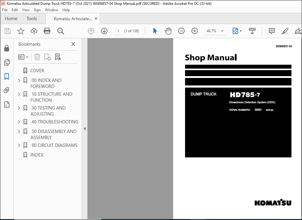
Komatsu HD785-7 Dump Truck Drowsiness Detection System (DDS) Shop Manual SEN06857-04 – PDF DOWNLOAD
Komatsu HD785-7 Dump Truck Drowsiness Detection System (DDS) Shop Manual SEN06857-04 – PDF DOWNLOAD
FILE DETAILS:
Komatsu HD785-7 Dump Truck Drowsiness Detection System (DDS) Shop Manual SEN06857-04 – PDF DOWNLOAD
Language : English
Pages : 138
Downloadable : Yes
File Type : PDF
Size: 3.25 MB
TABLE OF CONTENTS:
Komatsu HD785-7 Dump Truck Drowsiness Detection System (DDS) Shop Manual SEN06857-04 – PDF DOWNLOAD
00 INDEX AND FOREWORD 00-1
FOREWORD 00-4
BEFORE READING THIS MANUAL 00-4
10 STRUCTURE AND FUNCTION 10-1
CONTENTS 10-2
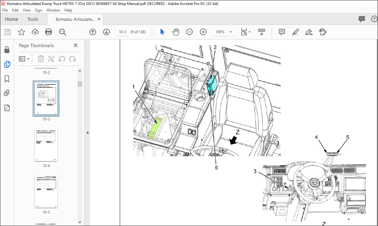
DROWSINESS DETECTION SYSTEM 10-3
LAYOUT DRAWING OF DROWSINESS DETECTION SYSTEM 10-3
SYSTEM DIAGRAM OF DROWSINESS DETECTION SYSTEM 10-4
SYSTEM DIAGRAM OF DROWSINESS DETECTION SYSTEM (EU SPECIFICATION) 10-5
FUNCTION OF DROWSINESS DETECTION SYSTEM 10-6
FUNCTION OF DROWSINESS DETECTION SYSTEM (EU SPECIFICATION) 10-7
OPERATION OF DROWSINESS DETECTION SYSTEM 10-8
COMPONENT PARTS OF DROWSINESS DETECTION SYSTEM 10-9
30 TESTING AND ADJUSTING 30-1
CONTENTS 30-2
ELECTRICAL SYSTEM 30-3
SET OPTIONAL SELECTION OF MACHINE MONITOR 30-3
40 TROUBLESHOOTING 40-1
CONTENTS 40-2
RELATED INFORMATION TO TROUBLESHOOT 40-3
CONNECTOR LIST AND LAYOUT 40-3
FUSE LOCATION TABLE 40-5
FAILURE CODE TABLE 40-7
TROUBLESHOOTING BY FAILURE CODE (DISPLAY OF CODE) 40-8
FAILURE CODE [D5WNKB] 40-8
FAILURE CODE [DR81KR] 40-9
FAILURE CODE [DR81MA] 40-14
FAILURE CODE [DV03KB] 40-15
FAILURE CODE [DV03KY] 40-16
FAILURE CODE [F9D0MC] 40-17
FAILURE CODE [F9D2KK] 40-18
FAILURE CODE [F9DSKR] 40-20
FAILURE CODE [ZA0010] 40-25
FAILURE CODE [ZA0011] 40-26
FAILURE CODE [ZA0012] 40-27
FAILURE CODE [ZA0013] 40-28
FAILURE CODE [ZA0014] 40-29
FAILURE CODE [ZA0015] 40-30
FAILURE CODE [ZA0016] 40-31
50 DISASSEMBLY AND ASSEMBLY 50-1
CONTENTS 50-2
RELATED INFORMATION ON DISASSEMBLY AND ASSEMBLY 50-3
HOW TO READ THIS MANUAL 50-3
SPECIAL TOOLS LIST 50-5
ELECTRICAL SYSTEM 50-6
REMOVE AND INSTALL DRIVER STATUS MONITOR 50-6
REMOVE AND INSTALL TRANSLATOR CONTROLLER 50-9
REMOVE AND INSTALL DROWSINESS DETECTION CAMERA 50-12
REMOVE AND INSTALL DROWSINESS ALARM BUZZER 50-15
REMOVE AND INSTALL DROWSINESS DETECTION WIRING HARNESS 50-30
90 CIRCUIT DIAGRAMS 90-1
CONTENTS 90-2
HOW TO READ THE CODES FOR ELECTRIC CABLE 90-3
ELECTRICAL CIRCUIT DIAGRAM 90-7
SYMBOLS USED IN ELECTRIC CIRCUIT DIAGRAM 90-7
ELECTRICAL CIRCUIT DIAGRAM (DROWSINESS DETECTION SYSTEM (DDS)) 90-11
INDEX 00 INDEX AND FOREWORD
00-2 HD785-7
INDEX 1
00 INDEX AND FOREWORD INDEX
DESCRIPTION:
Komatsu HD785-7 Dump Truck Drowsiness Detection System (DDS) Shop Manual SEN06857-04 – PDF DOWNLOAD
SERIAL NUMBERS 30001 and up
FOREWORD:
BEFORE READING THIS MANUAL:
- This shop manual contains only descriptions which are different from that of the standard machine (HD785-7:
Applicable machines 30001 and after) - For items which are not described in this shop manual, see the shop manual for the standard machine
(HD785-7: Applicable machines 30001 and after)
OPERATION OF DROWSINESS DETECTION SYSTEM
Preparation state
The system is started and starts the self-diagnosis when the starting switch is at the ON position. After the selfdiagnosis
is completed and the system is started normally, the operation notification sound (Three short beeps)
occurs, and the status goes to the normal operation state.
When a failure is sensed
When the Driver Status Monitor sensed
• The failure notification sound occurs from the notification sound speaker.
• Keep the preparation state.
When other than the Driver Status Monitor sensed
• The failure code is shown on the machine monitor.
• Keep the preparation state.
Normal operation state:
The system senses no abnormality and operates normally. The state is as follows.
• The drowsiness detection system ready lamp lights up.
• The operation notification sound and drowsiness alarm buzzer do not occur.
• If a failure is sensed during the normal operation state, the status changes to the preparation state.
Alarm state:
When short time sleep and drowsiness are sensed
The system judges that the operator sleeps for a short time or the drowsiness of operator is above the specified
level during the travel. The state is as follows.
• The drowsiness detection system ready lamp flashes.
• The alarm notification sound and drowsiness alarm buzzer occur.
• If a failure is sensed during the alarm state, the status changes to the preparation state.
When inattentive driving and loss of balance are sensed
The system judges that the operator looks aside or loses the balance during the travel. The state is as follows.
• The drowsiness detection system ready lamp flashes.
• The alarm notification sound occurs.
• If a failure is sensed during the alarm state, the status changes to the preparation state.
You can release the alarm state with one of the conditions that follow.
• When the system judges that the operator has no more short time sleep, inattentive driving, loss of balance,
and drowsiness.
• When the travel speed becomes below 1km/h.
IMAGES PREVIEW OF THE MANUAL:
