$37
Komatsu HYDRAULIC EXCAVATOR PC1250-11R PC1250SP-11R Field Assembly Manual – PDF DOWNLOAD
Komatsu HYDRAULIC EXCAVATOR PC1250-11R PC1250SP-11R Field Assembly Manual – PDF DOWNLOAD
DESCRIPTION:
Komatsu HYDRAULIC EXCAVATOR PC1250-11R PC1250SP-11R Field Assembly Manual – PDF DOWNLOAD
SERIAL NUMBERS 50077 and up
FOREWORD
Since this machine is large in size, it is divided into some units to meet the transportation conditions and regulations applied to the transportation route when shipped from our factory. This manual describes how to assemble the units into the complete machine in the field. We hope that this machine will display its quality and you will use it safely according to the operation manual. Many units are large in size and heavy in weight and may be handled in a dangerous place or posture and many workers may have to work together to sling them with cranes. Accordingly, before starting the assembly work, the work supervisor is required to hold a safety meeting to oblige the workers to put on pro tective gear and appoint a work leader and a crane work signal man and allot roles to all the workers for safe work. In particular, the above meeting is more important when worker of different languages and customs work together. The following is a reference supervision system diagram.
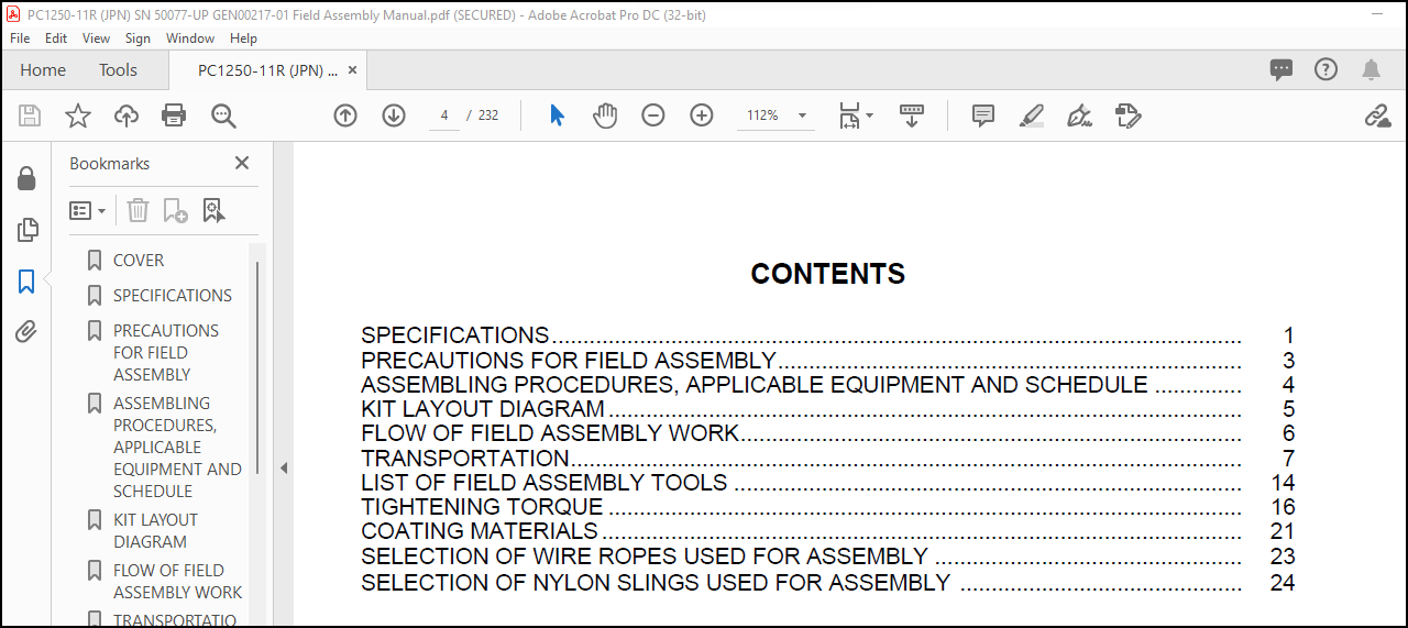
TABLE OF CONTENTS:
Komatsu HYDRAULIC EXCAVATOR PC1250-11R PC1250SP-11R Field Assembly Manual – PDF DOWNLOAD
SPECIFICATIONS 1
PRECAUTIONS FOR FIELD ASSEMBLY 3
ASSEMBLING PROCEDURES, APPLICABLE EQUIPMENT AND SCHEDULE 4
KIT LAYOUT DIAGRAM 5
FLOW OF FIELD ASSEMBLY WORK 6
TRANSPORTATION 7
LIST OF FIELD ASSEMBLY TOOLS 14
TIGHTENING TORQUE 16
COATING MATERIALS 21
SELECTION OF WIRE ROPES USED FOR ASSEMBLY 23
A ASSEMBLY OF CHASSIS 25
A- 1 Install RH and LH track frames 26
A- 2 Install travel piping 31
A- 3 Install travel piping covers 33
A- 4 Install steps 35
A- 5 Add grease to swing circle 36
A- 6 Assemble upper structure and undercarriage 37
A- 7 Install RH side step 39
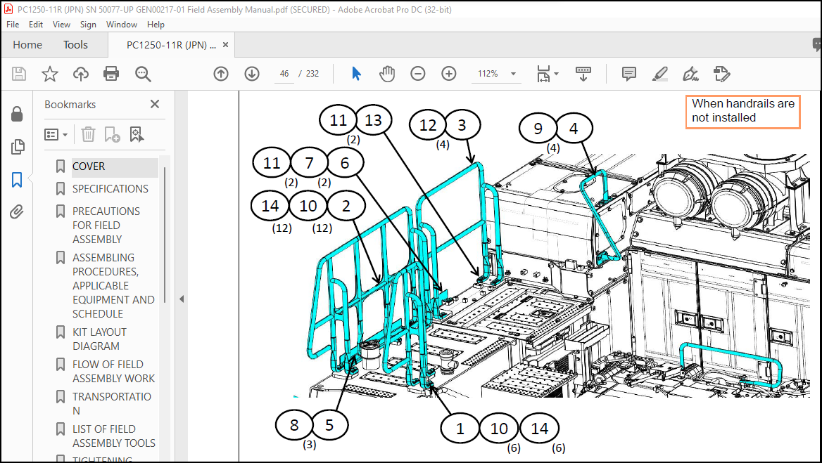
A- 8 Install handrails 40
A- 9 Install emergency stop switch on right front step (if equipped)
A-10 Install precleaner 42
A-11 Install swivel travel piping 44
A-17 Install KomVision camera 61
A-18 Install counterweight 69
A-19 Install counterweight revolving warning lamp (if equipped) 70
A-20 Install counterweight rear lamp (if equipped) 72
A-12 Install LH side step 45
A-13 Install fixed ladder 51
A-14 Install hydraulic stairway (if equipped) 53
A-15 Install flash light (if equipped) 58
A-16 Install LH side step emergency stop switch (if equipped) 60
A-21 Install radiator cover 74
A-22 Install exhaust tail pipe 75
A-23 Change installed position of step light 76
A-24 Change installed position of wireless LAN antenna 77
A-25 Install operator’s cab revolving warning lamp (if equipped) 78
A-26 Install operator’s cab handrail 80
A-27 Install LH rearview mirror 82
A-28 Install RH rearview mirror 84
A-29 Prepare for bleeding air from travel motor 86
A-30 Bleed air from hydraulic pump section 87
A-31 Tighten swing circle mounting bolts to specified torque 88
A-32 Check and adjust track tension 89
A-33 Check fuel, coolant and oil levels 92
A-34 Parts to be touched up after field assembly 94
B ASSEMBLING OF WORK EQUIPMENT OF BACKHOE 95
B- 1 Release remaining pressure in hydraulic circuit 96
B- 2 Install arm cylinder to boom 98
B- 3 Install arm cylinder hose 99
B- 4 Install boom cylinder to revolving frame 100
B- 5 Install boom cylinder hose 101
B- 6 Bleed air from cylinder 102
B- 7 Install boom foot dust seal 103
B- 8 Install boom assembly 104
B- 9 Install boom cylinder to boom assembly 105
B-10 Install boom connection hoses (between chassis and boom assembly) 106
B-11 Install arm assembly 107
B-12 Install bucket cylinder hoses (between boom and bucket cylinder) 109
B-13 Install bucket assembly 110
B-14 Clearance standard for installation of work equipment 113
B-15 Install work equipment grease piping 114
B-16 Install work equipment lamps 115
B-17 Grease after assembling work equipment 116
B-18 Bleed air from swing motor 117
B-19 Bleed air from travel motor 118
B-20 Install travel motor guard 119
B-21 Bleed air from hydraulic stairway (if equipped) 120
M PROCEDURE FOR INSPECTION AND MAINTENANCE AFTER COMPLETION
ASSEMBLY 121
M- 1 Replace return filter (Replace standard filter → flushing filter) 122
M- 2 Flush hydraulic circuit 124
M- 3 Replace return filter (Replace flushing filter → standard filter) 126
M- 4 Replace pilot filter 128
M- 5 Setting of KomVision (Camera calibration) 129
M- 7 Method for starting up KOMTRAX terminal and default setting of
KOMTRAX Plus controller 143
M- 6 Inspection method of 12m visibility (KomVision) 141
C PROCEDURE FOR ASSEMBLING OF WORK EQUIPMENT
OF LOADING SHOVEL 145
Transportation posture (only work equipment) 146
C- 1 Release remaining pressure in hydraulic circuit 147
C- 2 Bleed air from cylinder 149
C- 3 Flush hydraulic circuit 150
C- 4 Installation of Arm Cylinder Bottoms 151
C- 5 Connection of Boom and Arm 152
C- 6 Pulling out Boom Foot Pin and Boom Cylinder Foot Pin 154
C- 7 Installation of Boom and Arm Assembly 155
C- 8 Installation of Boom Hoses (Between Chassis and Boom) 156
C- 9 Installation of Hoses Between Boom and Arm (Bottom Dump) 157
C-10 Installation of Boom Cylinder Bottoms 158
C-11 Installation of Boom Cylinder Hoses 159
C-12 Installation of Boom Cylinder Head Pin 160
C-13 Installation of Arm Cylinder Hoses 161
C-14 Installation of Bucket Cylinder 162
C-15 Installation of Bucket Cylinder Hoses 163
C-16 Installation of Bucket Assembly 164
C-17 Installation of Bottom Dump Cylinder Hoses 166
C-18 Maintenance Standard 167
C-19 Installation of Working Lamp 168
C-20 Installation of Work Equipment Greasing Piping 169
C-21 Checking Oil Level in Hydraulic Tank and Adding Oil 170
C-22 Greasing After Assembling Work Equipment 171
Inspection of each part after assembly of loader 172
Field Assembly Inspecton Report
IMAGES PREVIEW OF THE MANUAL:
More products