$42
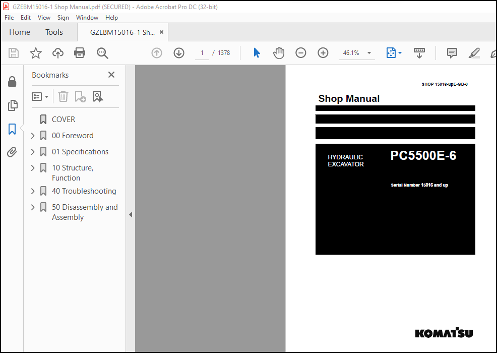
Komatsu HYDRAULIC MINING SHOVEL PC5500E-6 Shop Manual(15016-upE) – PDF DOWNLOAD
Komatsu HYDRAULIC MINING SHOVEL PC5500E-6 Shop Manual(15016-upE) – PDF DOWNLOAD
DESCRIPTION:
Serial Number 15016 and up
Komatsu HYDRAULIC MINING SHOVEL PC5500E-6 Shop Manual(15016-upE) – PDF DOWNLOAD
DIVISION OF THE BINDER
Part 1:
Operation Manual
Part 2:
Maintenance Manual
Part 3:
Depending on the volume of Part 3 a second Binder “Volume 2” is
being delivered with the Shovel. This Binder contains the General
Assembly Procedure Manual for the Shovel, Specification Booklet,
Service Literature for the Power Unit (Diesel Engine or Electric
Motor) and for Special Equipment. The Electrical- and
Hydraulic Diagrams are attached in the pocket of the front cover.
Refer to the -TABLE OF CONTENTS VOLUME 2 BINDERfor
details.
Read the Manuals before You Start the Engine.
Before operating the machine, familiarize yourself with its instruments
and controls.
Observe the instructions in these manuals for:
● your Personal SAFETY
● Operating SAFETY, and
● READY and EFFICIENT PERFORMANCE of your
KOMATSU Shovel.
Periodic preventive inspections and maintenance are the surest
means of keeping the machine in proper working order. Prompt
detection and correction of minor irregularities, and immediate
replacement of worn out or broken parts will prevent failures and
avoid expenses.
Replace damaged graphics and symbols.
Observe safety precautions to prevent injury and damage.
If you have any questions concerning this literature please contact
TABLE OF CONTENTS:
Komatsu HYDRAULIC MINING SHOVEL PC5500E-6 Shop Manual(15016-upE) – PDF DOWNLOAD
COVER………………………………………………………………………………………………………. 1
00 Foreword…………………………………………………………………………………………………. 3
Introduction…………………………………………………………………………………………….. 4
Safety Instructions………………………………………………………………………………………. 9
01 Specifications……………………………………………………………………………………………. 59
Specifications PC5500…………………………………………………………………………………….. 60
10 Structure, Function……………………………………………………………………………………….. 68
I. INTRODUCTION………………………………………………………………………………………….. 71
II. SAFETY………………………………………………………………………………………………. 9
III. SPECIFICATIONS………………………………………………………………………………………. 78
1. MAIN ASSEMBLY GROUPS…………………………………………………………………………………… 89
1.1 General layout……………………………………………………………………………………. 103
1.2 Superstructure……………………………………………………………………………………. 105
1.3 Power House………………………………………………………………………………………. 107
1.4 Hydraulic Oil Reservoir……………………………………………………………………………. 109
1.5 Hydraulic Oil Cooler………………………………………………………………………………. 111
1.6 Fuel tank (Fuel reservoir)…………………………………………………………………………. 113
1.7 Counter weight……………………………………………………………………………………. 115
1.8 Cab support………………………………………………………………………………………. 117
1.9 Operators cab…………………………………………………………………………………….. 119
1.10 Control blocks…………………………………………………………………………………… 121
1.11 Swing gears……………………………………………………………………………………… 123
1.12 Under carriage…………………………………………………………………………………… 125
2. DRIVE………………………………………………………………………………………………… 119
2.1 Prime drive assembly………………………………………………………………………………. 129
2.2 Engine and gearbox mount…………………………………………………………………………… 131
2.3 Torque supports…………………………………………………………………………………… 134
2.4 Radiator fan Drive Assy……………………………………………………………………………. 135
2.5 Pump distributor gearbox (PTO)……………………………………………………………………… 137
2.5.1 Spline shaft housing…………………………………………………………………………. 139
2.5.2 PTO lubrication and cooling…………………………………………………………………… 141
2.5.3 PTO valve adjustments………………………………………………………………………… 143
2.6 Coupling…………………………………………………………………………………………. 147
2.6.1 Rubber type coupling “Reich”, (replaces “Geislinger Coupling”)……………………………………. 147
2.6.2 Oil filled type coupling “Geisslinger”…………………………………………………………. 149
2.7 Air cleaner………………………………………………………………………………………. 151
3. HYDRAULIC OIL RESERVOIR………………………………………………………………………………… 135
3.1 Hydraulic oil reservoir……………………………………………………………………………. 155
3.2 Return and leak oil filter…………………………………………………………………………. 159
3.3 Breather Filter…………………………………………………………………………………… 163
3.4 Location of electrical components…………………………………………………………………… 165
4. HYDRAULIC OIL COOLING………………………………………………………………………………….. 149
4.1 General………………………………………………………………………………………….. 169
4.2 Hydraulic oil cooling circuit………………………………………………………………………. 171
4.3 Back pressure valve adjustment……………………………………………………………………… 175
4.4 Fan drive………………………………………………………………………………………… 177
4.4.1 Fan pump……………………………………………………………………………………. 179
4.4.2 Pressure relieve valve……………………………………………………………………….. 180
4.4.3 Temperature relay……………………………………………………………………………. 182
4.5 Cooler fan drive adjustment………………………………………………………………………… 183
5. CONTROLLING…………………………………………………………………………………………… 173
5.1 Pilot pressure supply and adjustment………………………………………………………………… 187
5.1.1 Pilot control arrangement…………………………………………………………………….. 189
5.1.2 Pilot pressure adjustment…………………………………………………………………….. 191
5.1.3 Check of Control Pressure…………………………………………………………………….. 193
5.2 Slew brakes………………………………………………………………………………………. 195
5.3 Travel parking brake………………………………………………………………………………. 198
5.4 Check of the pilot control logic……………………………………………………………………. 200
5.4.1 Check sheet FSA Page 1……………………………………………………………………….. 202
5.4.2 Check sheet BHA Page 1……………………………………………………………………….. 215
6. COMPONENTS……………………………………………………………………………………………. 221
6.1 Main control block and valve arrangement…………………………………………………………….. 225
6.1.1 FSA arrangement……………………………………………………………………………… 227
6.1.2 BHA arrangement……………………………………………………………………………… 231
6.2 Distributor manifold………………………………………………………………………………. 235
6.2.1 Front shovel attachment FSA…………………………………………………………………… 235
6.2.2 Back hoe attachment BHA………………………………………………………………………. 237
6.2.3 SRV with throttle check valve…………………………………………………………………. 239
6.2.4 Anti cavitation valve (check valve)……………………………………………………………. 241
6.3 Main control block………………………………………………………………………………… 243
6.3.1 Load holding valve…………………………………………………………………………… 249
6.3.2 High pressure filter…………………………………………………………………………. 251
6.3.3 Pressure relieve valves and anti-cavitation valve……………………………………………….. 253
6.3.4 Pressure relieve valves and anti-cavitation valve……………………………………………….. 255
6.4 Compact valve blocks………………………………………………………………………………. 257
6.5 Compact valve blocks………………………………………………………………………………. 259
6.6 Auxiliary gear pumps………………………………………………………………………………. 261
6.7 Hydraulic cylinder………………………………………………………………………………… 263
6.8 Swing ring……………………………………………………………………………………….. 265
7. MAIN HYDRAULIC PUMPS AND PUMP REGULATION…………………………………………………………………. 265
7.1 General………………………………………………………………………………………….. 269
7.1.1 Pump location……………………………………………………………………………….. 271
7.2 Main pump operating principles……………………………………………………………………… 273
7.2.1 Main pump function…………………………………………………………………………… 278
7.3 Main pump checks and adjustments……………………………………………………………………. 281
7.3.1 Peak point diesel engine test…………………………………………………………………. 281
7.3.2 Pressure transducer test……………………………………………………………………… 283
7.3.3 Cut off function…………………………………………………………………………….. 284
7.3.4 Pump regulation……………………………………………………………………………… 286
7.3.5 Swing pump volume reduction…………………………………………………………………… 287
7.4 Electronic pump regulation…………………………………………………………………………. 288
7.5 Pump Controller CR700……………………………………………………………………………… 291
7.6 Multi Monitor…………………………………………………………………………………….. 293
7.7 Multimonitor software instruction…………………………………………………………………… 295
7.7.1 Multimonitor main control…………………………………………………………………….. 295
7.7.2 Service Menu screen………………………………………………………………………….. 295
7.7.3 Monitoring (menu item 01)…………………………………………………………………….. 296
7.7.4 Abnormality Record (menu item 02)……………………………………………………………… 297
7.7.5 Default (menu item 03)……………………………………………………………………….. 300
7.7.6 Adjustment (menu item 04)…………………………………………………………………….. 301
7.7.7 Display Setup (menu item 05)………………………………………………………………….. 303
7.7.8 Table of fault messages and adjustments………………………………………………………… 304
7.8 Trouble shooting pump and pump regulation……………………………………………………………. 313
8. OPERATING HYDRAULIC……………………………………………………………………………………. 365
SM 15046-xD-GB-4.pdf………………………………………………………………………………….. 0
Contents and 00_Foreworda_15046_rev3.pdf…………………………………………………………….. 0
PC5500-6-D_Sec_1-0_rev5.pdf………………………………………………………………………… 0
PC5500-6-D_Sec_2-0_rev4.pdf………………………………………………………………………… 0
PC5500-6-D_Sec_3-0_rev1.pdf………………………………………………………………………… 0
PC5500-6-D_Sec_4-0_rev5.pdf………………………………………………………………………… 0
PC5500-6-D_Sec_5-0_rev4.pdf………………………………………………………………………… 0
PC5500-6-D_Sec_6-0_rev4.pdf………………………………………………………………………… 0
PC5500-6-D_Sec_7-0_rev6.pdf………………………………………………………………………… 0
PC5500-6-D_Sec_8-0_rev2.pdf………………………………………………………………………… 0
PC5500-6-D_Sec_8-1_rev3.pdf………………………………………………………………………… 0
PC5500-6-D_Sec_8-2_rev4.pdf………………………………………………………………………… 0
PC5500-6-D_Sec_8-3_rev2.pdf………………………………………………………………………… 537
PC5500-6-D_Sec_9-0_rev0.pdf………………………………………………………………………… 561
PC5500-6-D_Sec_10-0_rev1.pdf……………………………………………………………………….. 579
PC5500-6-D_Sec_11-0_rev0a.pdf………………………………………………………………………. 587
PC5500-6-D_Sec_12-0_rev3.pdf……………………………………………………………………….. 593
PC5500-6-D_Sec_13_0_rev0a.pdf………………………………………………………………………. 611
PC5500-6-D_Sec_14-0_rev2.pdf……………………………………………………………………….. 627
PC5500-6-D_Sec_15-0_rev2.pdf……………………………………………………………………….. 685
Safety.pdf……………………………………………………………………………………….. 0
SAFETY……………………………………………………………………………………….. 9
CONTENTS………………………………………………………………………………….. 10
Overview………………………………………………………………………………….. 11
NORMAL OPERATIONS………………………………………………………………………. 11
REGULAR MAINTENANCE…………………………………………………………………….. 11
TROUBLESHOOTING, ADJUSTMENTS AND REPAIR…………………………………………………… 11
ADDITIONAL SAFETY PRECAUTIONS FOR ASSEMBLING, DISASSEMBLING AND TRANSPORTATION OF THE EXCAVATOR…. 11
GENERAL PRECAUTIONS COMMON TO OPERATION ON THE EXCAVATOR……………………………………….. 12
PRECAUTIONS BEFORE STARTING OPERATION ON THE EXCAVATOR……………………………………… 12
PREPARATIONS FOR SAFE OPERATION………………………………………………………….. 12
FIRE PREVENTION………………………………………………………………………… 14
PRECAUTIONS WHEN GETTING ON OR OFF THE MACHINE…………………………………………….. 16
BURN PREVENTION………………………………………………………………………… 17
PRECAUTIONS WHEN CLEANING CAB GLASS………………………………………………………. 17
PRECAUTIONS RELATED TO PROTECTIVE STRUCTURES………………………………………………. 18
PRECAUTIONS AT JOBSITE………………………………………………………………….. 19
STARTING ENGINE………………………………………………………………………… 25
OPERATION……………………………………………………………………………… 26
PRECAUTION FOR MAINTENANCE………………………………………………………………….. 32
PRECAUTIONS FOR INSPECTION AND MAINTENANCE………………………………………………… 38
ADDITIONAL SAFETY INFORMATION FOR TROUBLESHOOTING AND ADJUSTMENTS……………………………….. 44
SPECIAL SAFETY EQUIPMENT……………………………………………………………………. 46
8.1 General layout……………………………………………………………………………………. 315
8.2 Floating function of boom and stick only FSA…………………………………………………………. 319
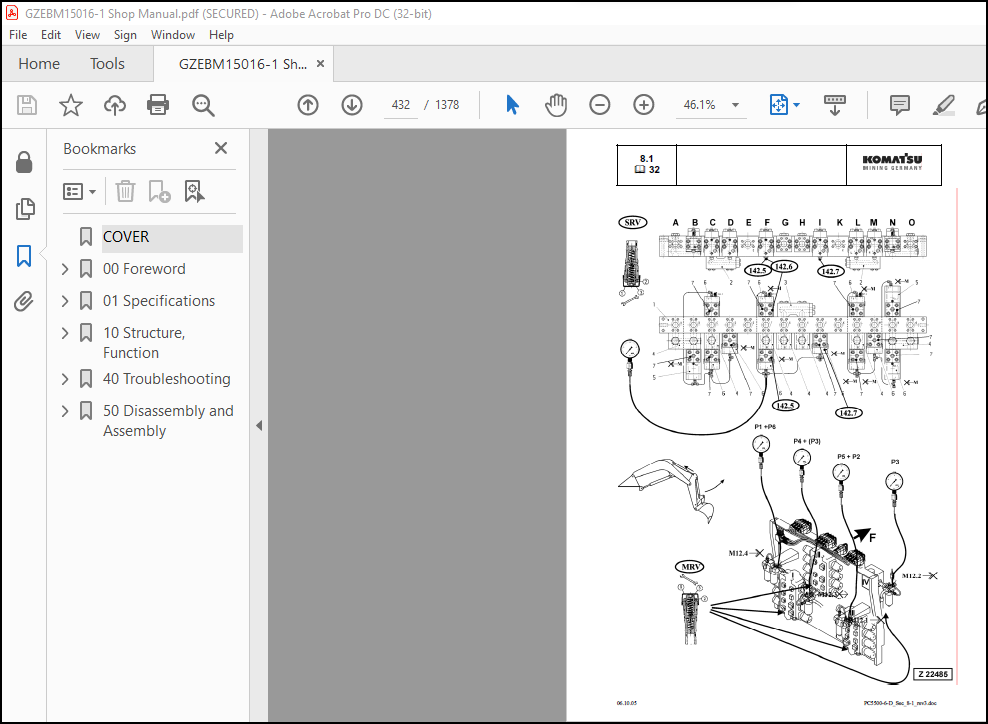
8.3 Check and Adjustments for MRV’s and SRV’s……………………………………………………………. 321
8.3.1 Check and Adjustments for MRV…………………………………………………………………. 323
8.3.2 Check and Adjustment for SRV’s………………………………………………………………… 325
8.3.3 Check and adjustment of the throttle check valves……………………………………………….. 333
8.4 Hydraulic for the swing circuit…………………………………………………………………….. 335
8.4.1 Hydraulic for the swing circuit……………………………………………………………….. 339
8.4.2 Slew gear box L & S………………………………………………………………………….. 343
8.4.3 Slew parking brake…………………………………………………………………………… 347
8.4.4 Slew service brake valve……………………………………………………………………… 351
8.4.5 Checks and adjustment of the slew pressure valve………………………………………………… 356
8.5 Travel circuit……………………………………………………………………………………. 359
8.5.1 Rotary joint………………………………………………………………………………… 361
8.5.2 Travel motor A2FMt…………………………………………………………………………… 363
8.5.3 Travel gear…………………………………………………………………………………. 365
8.5.4 Travel parking brake…………………………………………………………………………. 367
8.5.5 Travel control function………………………………………………………………………. 369
8.5.6 Check and Adjustment SRV travel system…………………………………………………………. 372
9. TRACK TENSION SYSTEM…………………………………………………………………………………… 541
9.1 General layout……………………………………………………………………………………. 375
9.2 Track tensioning function………………………………………………………………………….. 377
9.2.1 Cushioning………………………………………………………………………………….. 379
9.2.2 Pressure Increasing valve PIV…………………………………………………………………. 381
9.3 Track tensioning adjustment………………………………………………………………………… 385
9.3.1 Track tensioning function check……………………………………………………………….. 387
10. ACCESS LADDER HYDRAULICALLY OPERATED……………………………………………………………………. 559
10.1 Access ladder……………………………………………………………………………………. 391
10.2 Access ladder functional description……………………………………………………………….. 393
11. CABLE DRUM…………………………………………………………………………………………… 567
11.0.1 Functional description………………………………………………………………………….. 399
12. HINTS FOR READING THE HYDRAULIC CIRCUIT DIAGRAM………………………………………………………….. 581
12.1 General…………………………………………………………………………………………. 405
12.2 Symbolic………………………………………………………………………………………… 407
12.2.1 Lines, unions………………………………………………………………………………. 408
12.2.2 Components, valves………………………………………………………………………….. 410
12.2.3 Sensors……………………………………………………………………………………. 410
12.2.4 Valves, valve components…………………………………………………………………….. 411
12.2.5 Pump, motor, cylinder……………………………………………………………………….. 415
13. HINTS FOR READING THE ELECTRIC CIRCUIT DIAGRAM…………………………………………………………… 598
13.1 Designation of electrical components……………………………………………………………….. 422
13.2 Electric symbols…………………………………………………………………………………. 423
13.3 Symbols…………………………………………………………………………………………. 425
13.3.1 Drawing concept…………………………………………………………………………….. 427
13.3.2 Reading of the circuit diagram……………………………………………………………….. 433
14. ELECTRONIC CONTROL SYSTEM ECS………………………………………………………………………….. 615
14.1 General Function…………………………………………………………………………………. 439
15. AUTOMATIC LUBRICATION SYSTEM…………………………………………………………………………… 673
15.1 General Function…………………………………………………………………………………. 443
15.2 Function of a lubrication cycle……………………………………………………………………. 445
15.3 Lubrication pump drive……………………………………………………………………………. 453
15.4 Lubrication pump…………………………………………………………………………………. 455
15.4.1 Adjustments lubricating pump speed……………………………………………………………. 457
15.4.2 Adjustments lubricating pump pressure…………………………………………………………. 459
15.5 Lubricant Injector (metering valve)………………………………………………………………… 461
15.5.1 Connection of one or more injectors…………………………………………………………… 463
15.5.2 Function lubrication injector (metering valve)…………………………………………………. 465
15.6 End line pressure switch………………………………………………………………………….. 469
15.7 Lubricant in line filter………………………………………………………………………….. 471
15.8 Lubricant level sensor……………………………………………………………………………. 473
15.8.1 Capacitive digital type for machines with ETM………………………………………………….. 473
15.8.2 Capacitive analog type for machines with PLC…………………………………………………… 475
15.9 Lubrication system function and controlling…………………………………………………………. 477
15.9.1 Central Lubrication System (CLS) function and controlling with ETM system (PC 3000)………………… 479
15.9.2 Swing ring lubrication system (SLS) function and controlling with ETM system (PC3000)………………. 483
15.10 Adjustment of the lubrication system with ETM………………………………………………………. 490
15.11 Trouble shooting lubricating system……………………………………………………………….. 491
15.11.1 Lubrication pump cylinder does not move………………………………………………………. 492
15.11.2 Lubricant pressure built up very slowly or not at all………………………………………….. 494
15.11.3 Insufficient lubricant supply to one or more attachment bearings………………………………… 494
15.11.4 Insufficient lubricant at the swing ring gear…………………………………………………. 496
40 Troubleshooting…………………………………………………………………………………………… 741
Table of Contents………………………………………………………………………………………… 0
Introduction…………………………………………………………………………………………….. 0
Safety Notes…………………………………………………………………………………………. 0
Description of this Troubleshooting Manual………………………………………………………………. 0
General Precautions…………………………………………………………………………………… 0
Electrical Parts…………………………………………………………………………………………. 0
Componant Locations…………………………………………………………………………………… 0
Engine Electrical Parts……………………………………………………………………………….. 0
Electrical Parts On PTO, etc…………………………………………………………………………… 0
Electrical Parts on Pilot Control Frame…………………………………………………………………. 0
Electrical Parts on Main Hydraulic Reservoir…………………………………………………………….. 0
Electrical Parts on Switch Board X2…………………………………………………………………….. 0
Electrical Parts on Hydraulic Ldder…………………………………………………………………….. 0
Electrical Parts of Automatic Lube System……………………………………………………………….. 0
Electrical Parts on Air Cleaner and Fuel Tank……………………………………………………………. 0
Overview Connector Types………………………………………………………………………………. 0
Standard Value Table for Electrical Componants…………………………………………………………… 0
PT100 Temperature Charts………………………………………………………………………………. 0
Troubleshooting by Trouble Code……………………………………………………………………………. 0
Message 1 – Gear Lubrication out of Function (PTO)……………………………………………………….. 0
Message 2 – Engine Air Filter Restricted………………………………………………………………… 0
Message 3 – Filter for Control Oil Restricted……………………………………………………………. 0
Message 4 – Oil Tank Breather Filter Restricted………………………………………………………….. 0
Message 5 – Return Oil Filter Restricted………………………………………………………………… 0
Message 6 – Leak Oil Filter Restricted………………………………………………………………….. 0
Message 7 – Hydraulic Oil Temperature Too High…………………………………………………………… 0
Message 9 – Low Idle Too High Coolant Temperature………………………………………………………… 0
Message 10 – Engine Shutdown: Too Low Engine Oil Temperature………………………………………………. 0
Message 14 – Too Low Hydraulic Oil Level………………………………………………………………… 0
Message 15 – Caution, Slew Gear House Brake On…………………………………………………………… 0
Message 16 – Caution, Travel Gear House Brake On…………………………………………………………. 0
Message 17 – No Clearance For Starting, Shift Engine to Low Idle…………………………………………… 0
Message 18 – Central Lube System Fault………………………………………………………………….. 0
Message 19 – Slew Ring Gear Lubrication Fault……………………………………………………………. 0
Message 20 – Pilot Control Cut-Out……………………………………………………………………… 0
Message 21 – Central Lube System Empty Grease Barrel……………………………………………………… 0
Message 22 – Central Lube System Empty Grease Barre………………………………………………………. 0
Message 24 – Engine Problem: Stop All Control……………………………………………………………. 0
Message 32 – PTO Gear Lube Filter Restricted…………………………………………………………….. 0
Message 33 – Cooler Fan Drive Filter Restricted………………………………………………………….. 0
Message 39 – Engine Shutdown . Main Shut-Off (Gate) Volve…………………………………………………. 0
Message 42 – Too Low Coolant Pressure………………………………………………………………….. 0
Message 43 – Engine Shutdown: Emergency Stop Switch Actuated………………………………………………. 0
Message 44 – Engine Shutdown Safety Switch Actuated………………………………………………………. 0
Message 45 – Warning Signal from Engine Control Module……………………………………………………. 0
Message 48 – Too High PTO Gear Oil Temperature…………………………………………………………… 0
Message 50 – Caution, Pull Switch From Ground Man Actuated………………………………………………… 0
Message 51 – Engine Shutdown: Pull Switch From Ground Man Actuated…………………………………………. 0
Message 52 – Load Limit Clam Defective………………………………………………………………….. 0
Message 53 – Pressure Switch of CLS Actuated……………………………………………………………. 0
Message 55 – Refill Hyrdaulic Oil………………………………………………………………………. 0
Message 57 – Load Limit Regulation Fault………………………………………………………………… 0
Message 58 – Strainer Oil Cooler Restricted……………………………………………………………… 0
Message 59 – CLS Refill Grease Container………………………………………………………………… 0
Message 60 – SLS Refill Grease Barrel…………………………………………………………………… 0
Troubleshooting by Symptoms……………………………………………………………………………….. 0
Symptoms of the Hydraulic System……………………………………………………………………….. 0
50 Disassembly and Assembly…………………………………………………………………………………… 743
1. INTRODUCTION………………………………………………………………………………………….. 757
2. SAFETY……………………………………………………………………………………………….. 761
3. SUPERSTRUCTURE………………………………………………………………………………………… 793
4. UNDERCARRIAGE………………………………………………………………………………………….1071
5. ATTACHMENT…………………………………………………………………………………………….1185
6. SERVICE INFORMATION…………………………………………………………………………………….1361
IMAGES PREVIEW OF THE MANUAL:
More products