$40
Komatsu PC1250-7 PC1250SP-7 PC1250LC-7 Hydraulic Excavator Shop Manual SEBM027313 – PDF DOWNLOAD
Komatsu PC1250-7 PC1250SP-7 PC1250LC-7 Hydraulic Excavator Shop Manual SEBM027313 – PDF DOWNLOAD
FILE DETAILS:
Komatsu PC1250-7 PC1250SP-7 PC1250LC-7 Hydraulic Excavator Shop Manual SEBM027313 – PDF DOWNLOAD
Language : English
Pages : 980
Downloadable : Yes
File Type : PDF
Size: 49.6 MB
DESCRIPTION:
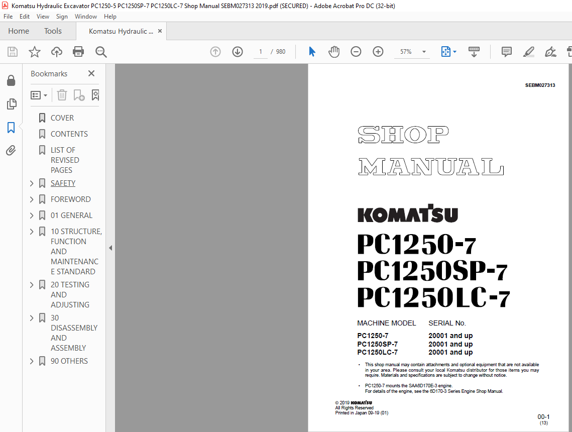
Komatsu PC1250-7 PC1250SP-7 PC1250LC-7 Hydraulic Excavator Shop Manual SEBM027313 – PDF DOWNLOAD
MACHINE MODEL SERIAL No.
PC1250-7 20001 and up
PC1250SP-7 20001 and up
PC1250LC-7 20001 and up
GENERAL PRECAUTIONS:
Mistakes in operation are extremely dangerous. Read the Operation and Maintenance Manual carefully BEFORE operating the machine.1. Before carrying out any greasing or repairs, read all the precautions given on the decals which are fixed to the machine.2. When carrying out any operation, always wear safety shoes and helmet. Do not wear loose work clothes, or clothes with buttons missing.• Always wear safety glasses when hitting parts with a hammer.• Always wear safety glasses when grinding parts with a grinder, etc.3. If welding repairs are needed, always have a trained, experienced welder carry out the work. When carrying out welding work, always wear welding gloves, apron, hand shield, cap and other clothes suited for welding work.4. When carrying out any operation with two or more workers, always agree on the operating procedure before starting. Always inform your fellow workers before starting any step of the operation. Before starting work, hang UNDER REPAIR signs on the controls in the operator’s compartment.5. Keep all tools in good condition and learn the correct way to use them.6. Decide a place in the repair workshop to keep tools and removed parts. Always keep the tools and parts in their correct places. Always keep the work area clean and make sure that there is no dirt or oil on the floor. Smoke only in the areas provided for smoking. Never smoke while working.
PREPARATIONS FOR WORK:
- 7. Before adding oil or making any repairs, park the machine on hard, level ground, and block the wheels or tracks to prevent the machine from moving.
- 8. Before starting work, lower blade, ripper, bucket or any other work equipment to the ground. If this is not possible, insert the safety pin or use blocks to prevent the work equipment from falling. In addition, be sure to lock all the control levers and hang warning signs on them.
- 9. When disassembling or assembling, support the machine with blocks, jacks or stands before starting work.
- 10.Remove all mud and oil from the steps or other places used to get on and off the machine. Always use the handrails, ladders or steps when getting on or off the machine. Never jump on or off the machine. If it is impossible to use the handrails, ladders or steps, use a stand to provide safe footing.
FOREWORD
GENERAL
This shop manual has been prepared as an aid to improve the quality of repairs by giving the serviceman an
accurate understanding of the product and by showing him the correct way to perform repairs and make judgements.
Make sure you understand the contents of this manual and use it to full effect at every opportunity.
This shop manual mainly contains the necessary technical information for operations performed in a service
workshop. For ease of understanding, the manual is divided into the following chapters; these chapters are further
divided into the each main group of components.
STRUCTURE AND FUNCTION
This section explains the structure and function of each component. It serves not only to give an understanding
of the structure, but also serves as reference material for troubleshooting.
In addition, this section may contain hydraulic circuit diagrams, electric circuit diagrams, and maintenance
standards.
TESTING AND ADJUSTING
This section explains checks to be made before and after performing repairs, as well as adjustments to
be made at completion of the checks and repairs.
Troubleshooting charts correlating “Problems” with “Causes” are also included in this section.
DISASSEMBLY AND ASSEMBLY
This section explains the procedures for removing, installing, disassembling and assembling each component,
as well as precautions for them.
MAINTENANCE STANDARD
This section gives the judgment standards for inspection of disassembled parts.
The contents of this section may be described in STRUCTURE AND FUNCTION.
OTHERS
This section mainly gives hydraulic circuit diagrams and electric circuit diagrams.
In addition, this section may give the specifications of attachments and options together.
TABLE OF CONTENTS:
Komatsu PC1250-7 PC1250SP-7 PC1250LC-7 Hydraulic Excavator Shop Manual SEBM027313 – PDF DOWNLOAD
COVER 1
CONTENTS 2
LIST OF REVISED PAGES 3
SAFETY 9
SAFETY NOTICE 9
FOREWORD 11
GENERAL 11
HOW TO READ THE SHOP MANUAL 12
HOISTING INSTRUCTIONS 13
METHOD OF DISASSEMBLING, CONNECTING PUSH-PULL TYPE COUPLER 14
COATING MATERIALS 16
STANDARD TIGHTENING TORQUE 18
ELECTRIC WIRE CODE 21
CONVERSION TABLE 22
UNITS 28
01 GENERAL 29
SPECIFICATION DIMENSION DRAWINGS 30
SPECIFICATIONS 34
WEIGHT TABLE 38
FUEL, COOLANT AND LUBRICANTS 42
10 STRUCTURE, FUNCTION AND MAINTENANCE STANDARD 43
PTO 44
PTO LUBRICATION SYSTEM 46
RADIATOR, OIL COOLER, AFTERCOOLER AND FUEL COOLER 48
POWER TRAIN 50
SWING MACHINERY 52
SWING CIRCLE 54
FINAL DRIVE 55
SPROCKET 58
TRACK FRAME 60
IDLER 62
CARRIER ROLLER 64
TRACK ROLLER 65
TRACK SHOE 66
AIR PIPING DIAGRAM 70
AIR CIRCUIT DIAGRAM 71
AIR GOVERNOR 72
AIR TANK 72
SAFETY VALVE 73
HORN VALVE 73
GREASE PUMP 74
HYDRAULIC EQUIPMENT LAYOUT DRAWING 76
HYDRAULIC TANK 81
HYDRAULIC PUMP 82
NO 1 PUMP 83
NO 2 PUMP 106
NO 3 PUMP 111
LINE OIL FILTER 120
PILOT OIL FILTER 121
RETURN OIL FILTER 122
DRAIN OIL FILTER 123
L H 5-SPOOL CONTROL VALVE 124
R H 4-SPOOL CONTROL VALVE 128
SWING 4-SPOOL CONTROL VALVE 132
STRAIGHT-TRAVEL VALVE 138
SWING MOTOR 141
CENTER SWIVEL JOINT 143
TRAVEL MOTOR 144
PPC CONTROL RELIEF VALVE 154
ACCUMULATOR 156
VALVE CONTROL 157
WORK EQUIPMENT, SWING PPC VALVE 158
TRAVEL PPC VALVE 164
SOLENOID VALVE 168
HYDRAULIC CYLINDER 176
WORK EQUIPMENT 180
DIMENSIONS OF WORK EQUIPMENT 184
AIR CONDITIONER 188
ENGINE CONTROL 189
HPI ENGINE CONTROL SYSTEM 195
MACHINE CONTROL SYSTEM 197
MONITOR SYSTEM 225
SENSOR 248
20 TESTING AND ADJUSTING 251
STANDARD VALUE TABLE FOR ENGINE RELATED PARTS 252
STANDARD VALUE TABLE FOR CHASSIS RELATED PARTS 256
TESTING AND ADJUSTING 275
TOOLS FOR TESTING, ADJUSTING AND TROUBLESHOOTING 276
MEASURING ENGINE SPEED 280
MEASURING AIR SUPPLY PRESSURE (BOOST PRESSURE) 281
MEASURING EXHAUST TEMPERATURE 282
TROUBLESHOOTING FOR INJECTOR 283
MEASURING EXHAUST COLOR 284
ADJUSTING VALVE CLEARANCE 285
ADJUSTING INJECTOR SET LOAD 286
MEASURING COMPRESSION PRESSURE 288
MEASURING BLOW-BY PRESSURE 290
MEASURING ENGINE OIL PRESSURE 291
HANDLING EQUIPMENT IN FUEL SYSTEM 292
MEASURING FUEL CIRCUIT PRESSURE 293
VISUAL INSPECTION OF RETURN FUEL 295
ARRANGEMENT OF CONTROL DEVICES FOR HPI 296
BLEEDING AIR FROM FUEL CIRCUIT 299
ADJUSTING ENGINE SPEED SENSOR 301
REPLACING AND ADJUSTING FAN BELT 302
TESTING AND ADJUSTING ALTERNATOR AND AIR COMPRESSOR BELT TENSION 303
TESTING CLEARANCE OF SWING CIRCLE BEARING 305
MEASURING WEAR OF SPROCKET 306
TESTING AND ADJUSTING TRACK SHOE TENSION 307
TESTING AND ADJUSTING HYDRAULIC PRESSURE IN WORK EQUIPMENT, SWING, TRAVEL CIRCUIT 308
TESTING AND ADJUSTING CONTROL CIRCUIT OIL PRESSURE 315
TESTING AND ADJUSTING PISTON PUMP CONTROL PRESSURE 316
TESTING SERVO PISTON STROKE 323
MEASURING PPC VALVE OUTPUT PRESSURE AND TESTINGS WING PPC SHUTTLE VALVE 324
MEASURING SOLENOID VALVE OUTPUT PRESSURE 328
ADJUSTING WORK EQUIPMENT, SWING PPC VALVE 330
TESTING TRAVEL DEVIATION 331
TESTING LOCATIONS CAUSING HYDRAULIC DRIFT OF WORK EQUIPMENT 332
MEASURING OIL LEAKAGE 333
MEASURING FAN SPEED 337
MEASURING FAN CIRCUIT OIL PRESSURE 337
BLEEDING AIR 339
RELEASING REMAINING PRESSURE IN HYDRAULIC CIRCUIT 341
INSPECTION PROCEDURES FOR DIODE 342
SPECIAL FUNCTION OF MONITOR PANEL 343
INITIALIZATION PROCEDURES FOR VHMS CONTROLLER 373
SETTING PROCEDURES FOR REPLACING VHMS CONTROLLER 386
TESTING AND ADJUSTING DEVICES RELATED TO VHMS 401
PM-CLINIC SERVICE 405
TROUBLESHOOTING 419
POINTS TO REMEMBER WHEN TROUBLESHOOTING 420
SEQUENCE OF EVENTS IN TROUBLESHOOTING 421
POINTS TO REMEMBER WHEN CARRYING OUT MAINTENANCE 422
CHECKS BEFORE TROUBLESHOOTING 430
CLASSIFICATION AND STEPS FOR TROUBLESHOOTING 431
CONNECTOR ALLOCATION DRAWING AND ELECTRICAL CIRCUIT DIAGRAM FOR EACH SYSTEM 435
CONNECTION TABLE FOR CONNECTOR PIN NUMBERS 458
T-BRANCH BOX AND T-BRANCH TABLE 482
TROUBLESHOOTING WHEN ERROR CODE (ELECTRICAL SYSTEM) AND FAILURE CODE (MECHANICAL SYSTEM) ARE DISPLAYED (1/2) 485
INFORMATION IN TROUBLESHOOTING TABLE 486
Error code in Electrical System C111 (ECM Microprocessor) 488
Error code in Electrical System C112 (Timing Actuator Stuck) 488
Error code in Electrical System C113 (Timing Actuator Current) 489
Error code in Electrical System C115 (Engine Speed Sensor (2)) 490
Error code in Electrical System C116 (Timing Rail P Sensor) 492
Error code in Electrical System C117 (Timing Rail P Sensor) 493
Error code in Electrical System C118 (Fuel Pump P Sensor) 494
Error code in Electrical System C119 (Fuel Pump P Sensor) 496
Error code in Electrical System C121 (Engine Speed Sensor (1)) 496
Error code in Electrical System C122 (Boost P Sensor) 498
Error code in Electrical System C123 (Boost P Sensor) 499
Error code in Electrical System C131 (Throttle Sensor) 500
Error code in Electrical System C132 (Throttle Sensor) 501
Error code in Electrical System C135 (Oil P Sensor) 502
Error code in Electrical System C141 (Oil P Sensor) 504
Error code in Electrical System C143 (Oil P Low) 504
Error code in Electrical System C144 (Coolant T Sensor) 505
Error code in Electrical System C145 (Coolant T Sensor) 507
Error code in Electrical System C151 (Coolant T High) 507
Error code in Electrical System C153 (Intake Manifold T Sensor) 508
Error code in Electrical System C154 (Intake Manifold T Sensor) 509
Error code in Electrical System C222 (Ambient Air P Sensor) 512
Error code in Electrical System C234 (Engine Overspeed) 512
Error code in Electrical System C254 (FSOV Circuit) 513
Error code in Electrical System C259 (FSOV Circuit) 514
Error code in Electrical System C261 (Fuel T High) 514
Error code in Electrical System C263 (Fuel T Sensor) 515
Error code in Electrical System C265 (Fuel T Sensor) 516
Error code in Electrical System C316 (Fuel Pump Actuator Current) 517
Error code in Electrical System C318 (Fuel Pump Actuator Stuck) 518
Error code in Electrical System C346 (ECM Powerdown) 520
Error code in Electrical System C423 (Timing Rail P In Range Error) 522
Error code in Electrical System C441 (Battery Voltage) 524
Error code in Electrical System C442 (Battery Voltage) 524
Error code in Electrical System C451 (Fuel Rail P Sensor) 525
Error code in Electrical System C452 (Fuel Rail P Sensor) 526
Error code in Electrical System C455 (Fuel Rail Actuator Current) 527
Error code in Electrical System C467 (Timing Actuator Control) 528
Error code in Electrical System C468 (Rail Actuator Control) 528
Error code in Electrical System C514 (Rail Actuator Stuck) 529
Error code in Electrical System C554 (Fuel Rail P In Range Error) 530
TROUBLESHOOTING WHEN ERROR CODE (ELECTRICAL SYSTEM) AND FAILURE CODE (MECHANICAL SYSTEM) ARE DISPLAYED (2/2) 533
Error Code in Electrical System E101 (Abnormality Error Record) 536
Error Code in Electrical System E112 (Wiper Drive (For) S/C) 538
Error Code in Electrical System E113 (Wiper Drive (Rev) S/C) 542
Error Code in Electrical System E114 (Washer Drive S/C) 544
Error Code in Electrical System E115 (Wiper Working Abnormality) 546
Error Code in Electrical System E116 (Wiper Parking Abnormality) 548
Error Code in Electrical System E201 (CO Cancel Sol S/C) 552
Error Code in Electrical System E202 (Travel Junction Sol S/C) 554
Error Code in Electrical System E203 (Swing Brake Sol S/C) 556
Error Code in Electrical System E204 (2-stage Relief Sol S/C)User Code 558
Error Code in Electrical System E205 (Swing Priority Sol S/C)User Code 560
Error Code in Electrical System E206 (Travel Speed Sol S/C) 562
Error Code in Electrical System E207 (Flash Light Relay S/C) 564
Error Code in Electrical System E211 (CO Cancel Sol Disc ) 566
Error Code in Electrical System E212 (Travel Junction Sol Disc ) 568
Error Code in Electrical System E213 (Swing Brake Sol Disc ) 570
Error Code in Electrical System E214 (2-stage Relief Sol Disc ) 572
Error Code in Electrical System E215 (Swing Priority Sol Disc ) 574
Error Code in Electrical System E216 (Travel Speed Sol Disc ) 576
Error Code in Electrical System E217 (Model selection Abnormality) 578
Error Code in Electrical System E218 (S-Net Comm Disc ) 580
Error Code in Electrical System E221 (J1939 Comm Error) 582
Error Code in Electrical System E222 (Working Mode Output S/C (1)) 584
Error Code in Electrical System E223 (Working Mode Output Disc (1)) 585
Error Code in Electrical System E224 (Working Mode Output S/C (2)) 586
Error Code in Electrical System E225 (Working Mode Output Disc (2)) 587
Error Code in Electrical System E226 (Auto-deceleration Output Disc ) 588
Error Code in Electrical System E227 (Engine Speed Sensor Abnormality) 589
Error Code in Electrical System E228 (Auto-deceleration Output S/C) 590
Error Code in Electrical System E232 (TVC Sol S/C) 592
Error Code in Electrical System E233 (TVC Sol Disc ) 594
Error Code in Electrical System E234 (Lever Neutral Output S/C) 596
Error Code in Electrical System E235 (Lever Neutral Output Disc ) 597
Error Code in Electrical System E241 (Pre Sens Voltage Failure) 598
Error Code in Electrical System E242 (F Pump Pre Sens Failure) 600
Error Code in Electrical System E243 (R Pump Pre Sens Failure) 602
Error Code in Electrical System E244 (Swing Pre Sens Failure) 604
Error Code in Electrical System E245 (High relief press F Pump) 606
Error Code in Electrical System E246 (High relief press R Pump) 607
Error Code in Electrical System E247 (High relief press pump swing) 608
Error Code in Electrical System E302 (Step Light Relay S/C) 610
Error Code in Electrical System E304 (Step Light Power Drive Relay S/C) 612
Error Code in Electrical System E315 (Battery Relay Drive S/C) 614
Failure Code in VHMS System A000N1 (Engine Over Speed) 616
Failure Code in Mechanical System AA10NX (Aircleaner Clogging) 618
Failure Code in Mechanical System AB00KE (Charge Voltage Low) 620
Failure Code in Mechanical System B@BAZG (Eng Oil Press Low) 622
Failure Code in Mechanical System B@BAZK (Eng Oil Level Low) 623
Failure Code in Mechanical System B@BCNS (Eng Water Overheat) 624
Failure Code in Mechanical System B@BCZK (Eng Water Lvl Low) 626
Failure Code in VHMS System B@CBNS (High PTO temperature) 628
Failure Code in Mechanical System B@HANS (Hydr Oil Overheat) 629
Failure Code in VHMS System DBB0KK (VHMS source voltage Error) 630
Failure Code in VHMS System DBB5KP (VHMS 5V source sys Error) 632
Failure Code in VHMS System DBB6KP (VHMS 24V source sys Error) 633
Failure Code in VHMS System DBBQKR (KOM-NET/c error) 634
Failure Code in VHMS System DBBRKR (CAN-NET sys (J1939) Error) 636
Failure Code in VHMS System DGE1KB (Eng Oil Temp Sensor Failure) 638
Failure Code in VHMS System DGE1KY (Eng Oil Temp Sensor Failure) 640
Failure Code in VHMS System DGE5KX (Ambient Air Temp Sensor Failure) 642
Failure Code in VHMS System DGT3KZ (PTO Temp Sensor Failure) 644
Failure Code in VHMS System DGT4KA (F Exhaust Temp Sensor Failure) 646
Failure Code in VHMS System DGT4KB (F Exhaust Temp Sensor Failure) 648
Failure Code in VHMS System DGT5KA (R Exhaust Temp Sensor Failure) 650
Failure Code in VHMS System DGT5KB (R Exhaust Temp Sensor Failure) 652
Failure Code in VHMS System DHE5KB (Blowby Pres Sensor Failure) 654
Failure Code in VHMS System DHE5KY (Blowby Pres Sensor Failure) 656
Failure Code in VHMS System F@BBZL (High Blowby Pressure) 658
Failure Code in VHMS System F@BYNR (High F cyl Exhaust Temp 2) 659
Failure Code in VHMS System F@BYNS (High F cyl Exhaust Temp 1) 660
Failure Code in VHMS System F@BZNR (High R cyl Exhaust Temp 2) 661
Failure Code in VHMS System F@BZNS (High R cyl Exhaust Temp 1) 662
Failure Code in VHMS System J100KA (Cnt Pump Pre Sens Failure) 664
Failure Code in VHMS System j100KA (Fan Pump Pre Sens Failure) 666
Failure Code in VHMS System J100KB (Cnt Pump Pre Sens Failure) 668
Failure Code in VHMS System j100KB (Fan Pump Pre Sens Failure) 670
Failure Code in VHMS System J100L6 (Abnomal Cnt gear pump press) 672
Failure Code in VHMS System j100L6 (Abnomal Fan gear pump press) 674
TROUBLESHOOTING OF ELECTRICAL SYSTEM (E-MODE) 677
INFORMATION CONTAINED IN TROUBLESHOOTING TABLE 678
E-1 Engine does not start (Engine does not rotate) 679
E-2 Auto-decelerator does not work 682
E-3 Auto engine warm-up device does not work 683
E-4 Preheater does not work 684
E-5 All work equipment, swing and travel do not move 686
E-6 Machine push-up circuit does not work 688
E-7 Boom shockless circuit cannot be reset 690
E-8 No display in monitor panel at all 692
E-9 Part of display on monitor panel is missing 693
E-10 Monitor panel displays contents irrelevant to the model 693
E-11 Fuel level monitor red lamp lights up while engine is running 694
E-12 Hydraulic oil temperature gauge does not display correctly 695
E-13 Fuel gauge does not display correctly 696
E-14 Swing lock monitor does not display correctly 697
E-15 When the monitor switch is operated, no display appears 698
E-16 Windshield wiper does not work 699
E-17 Alarming buzzer cannot be cancelled 702
E-18 “Boom RAISE” is not correctly displayed in monitor function 703
E-19 “Boom LOWER” is not correctly displayed in monitor function 704
E-20 “Arm DIGGING” is not correctly displayed in monitor function 705
E-21 “Arm DUMPING” is not correctly displayed in monitor function 706
E-22 “Bucket DIGGING” is not correctly displayed in monitor function 707
E-23 “Bucket DUMPING” is not correctly displayed in monitor function 708
E-24 “SWING” is not correctly displayed in monitor function 710
E-25 “TRAVEL” is not correctly displayed in monitor function 712
E-26 Air Conditioner does not work 714
E-27 Travel alarm does not sound 715
E-28 Any of panel lamp, head lamp, working lamp (including additional lamp) does not light up 716
TROUBLESHOOTING OF HYDRAULIC, MECHANICAL SYSTEM (H MODE) 721
BEFORE TROUBLESHOOTING FOR HYDRAULIC AND MECHANICAL SYSTEMS 722
INFORMATION IN TROUBLESHOOTING TABLE 727
H-1 Speed or power of all work equipment, travel, and swing is low 728
H-2 Engine speed lowers remarkably or engine stalls 730
H-3 All work equipment, travel, and swing systems do not work 731
H-4 Abnormal sound is heard from around pump 732
H-5 Speed or power of boom is low 733
H-6 Speed or power of arm is low 735
H-7 Speed or power of bucket is low 736
H-8 Boom does not move 737
H-9 Arm does not move 737
H-10 Bucket does not move 737
H-11 Hydraulic drift of work equipment is large 738
H-12 Time lag of work equipment is large 739
H-13 Boom shockless function cannot be turned ON or OFF 740
H-14 Machine deviates in one direction 740
H-15 Machine deviates largely at start 742
H-16 Machine deviates largely during compound ope 743
H-17 Travel speed or power is low 743
H-18 Machine does not travel (only one track) 744
H-19 Travel speed does not change 745
H-20 Machine does not swing 746
H-21 Swing speed or acceleration is low 747
H-22 Swing speed or power is low in compound operation of travel and bucket 748
H-23 Swing speed or power is low in compound operation of travel and boom in swing priority mode 748
H-24 Upper structure overruns largely 749
H-25 Large shocks are made when upper structure stops swingi 750
H-26 Large abnormal sounds are made when upper structure stops swinging 751
H-27 Hydraulic drift of swing is large 751
TROUBLESHOOTING OF ENGINE BODY (S MODE) 753
POINTS TO REMEMBER WHEN TROUBLESHOOTING 754
METHOD OF USING TROUBLESHOOTING CHARTS 755
S-1 STARTING PERFORMANCE IS POOR (STARTING ALWAYS TAKES TIME) 758
S-2 ENGINE DOES NOT START 760
S-3 ENGINE DOES NOT PICK UP SMOOTHLY (FOLLOW-UP IS POOR) 766
S-4 ENGINE STOPS DURING OPERATIONS 768
S-5 ENGINE DOES NOT ROTATE SMOOTHLY (HUNTING) 770
S-6 ENGINE LACKS OUTPUT (OR LACKS POWER) 772
S-7 EXHAUST SMOKE IS BLACK (INCOMPLETE COMBUSTION) 774
S-8 OIL CONSUMPTION IS EXCESSIVE (OR EXHAUST SMOKE IS BLUE) 776
S-9 OIL BECOMES CONTAMINATED QUICKLY 777
S-10 FUEL CONSUMPTION IS EXCESSIVE 778
S-11 OIL IS IN COOLANT, OR COOLANT SPURTS BACK, OR COOLANT LEVEL GOES DOWN 779
S-12 OIL PRESSURE CAUTION LAMP LIGHTS UP (DROP IN OIL PRESSURE) 780
S-13 OIL LEVEL RISES 781
S-14 COOLANT TEMPERATURE BECOMES TOO HIGH (OVERHEATING) 782
S-15 ABNORMAL NOISE IS MADE 783
S-16 VIBRATION IS EXCESSIVE 784
30 DISASSEMBLY AND ASSEMBLY 785
HOW TO READ THIS MANUAL 789
REMOVAL AND INSTALLATIONOF ASSEMBLIES 789
DISASSEMBLY AND ASSEMBLYOF ASSEMBLIES 790
PRECAUTIONS WHEN PERFORMING OPERATION 791
SPECIAL TOOL LIST 793
SKETCHES OF SPECIAL TOOLS 797
REMOVAL AND INSTALLATION OF FUEL PUMP ASSEMBLY 803
REMOVAL 803
INSTALLATION 803
REMOVAL AND INSTALLATION OF ENGINE FRONT SEAL 804
SPECIAL TOOLS 804
REMOVAL 804
INSTALLATION 804
REMOVAL AND INSTALLATION OF ENGINE REAR SEAL 806
SPECIAL TOOLS 806
REMOVAL 806
INSTALLATION 806
REMOVAL AND INSTALLATION OF CYLINDER HEAD ASSEMBLY 808
SPECIAL TOOLS 808
REMOVAL 808
INSTALLATION 811
REMOVAL AND INSTALLATION OF FUEL COOLER AND AIR CONDITIONER ASSEMBLY 813
SPECIAL TOOLS 813
REMOVAL 813
INSTALLATION 814
REMOVAL AND INSTALLATION OF AFTERCOOLER ASSEMBLY 815
REMOVAL 815
INSTALLATION 815
REMOVAL AND INSTALLATION OF RADIATOR, HYDRAULIC COOLER ASSEMBLY 816
REMOVAL 816
INSTALLATION 817
REMOVAL AND INSTALLATION OF ENGINE, PTO, HYDRAULIC PUMP ASSEMBLY 818
REMOVAL 818
INSTALLATION 821
REMOVAL AND INSTALLATION OF PTO ASSEMBLY 822
REMOVAL 822
INSTALLATION 823
DISASSEMBLY AND ASSEMBLY OF PTO ASSEMBLY 824
DISASSEMBLY 824
ASSEMBLY 826
REMOVAL AND INSTALLATION OF FUEL TANK ASSEMBLY 828
REMOVAL 828
INSTALLATION 828
DISASSEMBLY AND ASSEMBLY OF FINAL DRIVE ASSEMBLY 829
SPECIAL TOOLS 829
DISASSEMBLY 829
ASSEMBLY 833
SKETCHES OF SPECIAL TOOLS 839
REMOVAL AND INSTALLATION OF REVOLVING FRAME ASSEMBLY 840
REMOVAL 840
INSTALLATION 840
REMOVAL AND INSTALLATION OF SWING MACHINERY ASSEMBLY 841
REMOVAL 841
INSTALLATION 841
DISASSEMBLY AND ASSEMBLY OF SWING MACHINERY ASSEMBLY 842
SPECIAL TOOLS 842
DISASSEMBLY 842
ASSEMBLY 845
SKETCHES OF SPECIAL TOOLS 849
REMOVAL AND INSTALLATION OF SWING CIRCLE ASSEMBLY 851
REMOVAL 851
INSTALLATION 851
REMOVAL AND INSTALLATION OF TRACK SHOE ASSEMBLY 852
SPECIAL TOOLS 852
REMOVAL 852
INSTALLATION 853
REMOVAL AND INSTALLATION OF IDLER ASSEMBLY 854
REMOVAL 854
INSTALLATION 854
DISASSEMBLY AND ASSEMBLY OF IDLER ASSEMBLY 855
SPECIAL TOOLS 855
DISASSEMBLY 855
ASSEMBLY 856
DISASSEMBLY AND ASSEMBLY OF IDLER ADJUSTMENT CYLINDER ASSEMBLY 858
DISASSEMBLY 858
ASSEMBLY 858
REMOVAL AND INSTALLATION OF RECOIL SPRING ASSEMBLY 859
REMOVAL 859
INSTALLATION 859
DISASSEMBLY AND ASSEMBLY OF RECOIL SPRING ASSEMBLY 861
SPECIAL TOOLS 861
DISASSEMBLY 861
INSTALLATION 862
SKETCHES OF SPECIAL TOOLS 863
REMOVAL AND INSTALLATION OF CARRIER ROLLER ASSEMBLY 864
REMOVAL 864
INSTALLATION 864
DISASSEMBLY AND ASSEMBLY OF CARRIER ROLLER ASSEMBLY 865
SPECIAL TOOLS 865
DISASSEMBLY 865
ASSEMBLY 866
SKETCHES OF SPECIAL TOOLS 867
REMOVAL AND INSTALLATION OF TRACK ROLLER ASSEMBLY 868
SPECIAL TOOLS 868
REMOVAL 868
INSTALLATION 868
DISASSEMBLY AND ASSEMBLY OF TRACK ROLLER ASSEMBLY 869
SPECIAL TOOLS 869
DISASSEMBLY 869
ASSEMBLY 870
REMOVAL AND INSTALLATION OF HYDRAULIC TANK ASSEMBLY 872
REMOVAL 872
INSTALLATION 873
REMOVAL AND INSTALLATION OF HYDRAULIC PUMP ASSEMBLY 874
REMOVAL 874
INSTALLATION 874
REMOVAL AND INSTALLATION OF MAIN PUMP INPUT SHAFT OIL SEAL 875
REMOVAL 875
INSTALLATION 875
DISASSEMBLY AND ASSEMBLY OF MAIN RELIEF VALVE ASSEMBLY 876
DISASSEMBLY 876
ASSEMBLY 876
REMOVAL AND INSTALLATION OF 5-SPOOL CONTROL VALVE ASSEMBLY (NO 1) 877
REMOVAL 877
INSTALLATION 878
REMOVAL AND INSTALLATION OF 4-SPOOL CONTROL VALVE ASSEMBLY (NO 2) 879
REMOVAL 879
INSTALLATION 880
REMOVAL AND INSTALLATION OF 4-SPOOL CONTROL VALVE ASSEMBLY (NO 3) 881
REMOVAL 881
INSTALLATION 882
DISASSEMBLY AND ASSEMBLY OF CONTROL VALVE ASSEMBLY (NO 1) 883
DISASSEMBLY 883
ASSEMBLY 884
DISASSEMBLY AND ASSEMBLY OF CONTROL VALVE ASSEMBLY (NO 2) 886
DISASSEMBLY 886
ASSEMBLY 887
DISASSEMBLY AND ASSEMBLY OF CONTROL VALVE ASSEMBLY (NO 3) 890
DISASSEMBLY 890
ASSEMBLY 891
REMOVAL AND INSTALLATION OF SWING MOTOR ASSEMBLY 893
REMOVAL 893
INSTALLATION 894
REMOVAL AND INSTALLATION OF CENTER SWIVEL JOINT ASSEMBLY 895
REMOVAL 895
INSTALLATION 895
DISASSEMBLY AND ASSEMBLY OF CENTER SWIVEL JOINT ASSEMBLY 896
DISASSEMBLY 896
ASSEMBLY 896
REMOVAL AND INSTALLATIONOF TRAVEL MOTOR ASSEMBLY 897
SPECIAL TOOLS 897
REMOVAL 897
INSTALLATION 897
DISASSEMBLY AND ASSEMBLY OF WORK EQUIPMENT PPC VALVE ASSEMBLY 898
DISASSEMBLY 898
ASSEMBLY 899
DISASSEMBLY AND ASSEMBLY OF TRAVEL PPC VALVE ASSEMBLY 900
DISASSEMBLY 900
ASSEMBLY 901
REMOVAL AND INSTALLATION OF BUCKET CYLINDER ASSEMBLY 902
REMOVAL 902
INSTALLATION 903
REMOVAL AND INSTALLATION OF BUCKET CYLINDER ASSEMBLY (LOADING SHOVEL) 904
REMOVAL 904
INSTALLATION 905
REMOVAL AND INSTALLATION OF BOTTOM DUMP CYLINDER ASSEMBLY (LOADING SHOVEL) 906
REMOVAL 906
INSTALLATION 907
REMOVAL AND INSTALLATION OF ARM CYLINDER ASSEMBLY (BACKHOE SPECIFICATION) 908
SPECIAL TOOLS 908
REMOVAL 908
INSTALLATION 909
SKETCHES OF SPECIAL TOOLS 910
REMOVAL AND INSTALLATION OF ARM CYLINDER ASSEMBLY (LOADING SHOVEL) 911
REMOVAL 911
INSTALLATION 912
REMOVAL AND INSTALLATION OF BOOM CYLINDER ASSEMBLY (BACKHOE SPECIFICATION) 913
SPECIAL TOOLS 913
REMOVAL 913
INSTALLATION 914
REMOVAL AND INSTALLATION OF BOOM CYLINDER ASSEMBLY (LOADING SHOVEL) 915
REMOVAL 915
INSTALLATION 916
DISASSEMBLY AND ASSEMBLY OF HYDRAULIC CYLINDER ASSEMBLY (BACKHOE SPECIFICATION) 917
SPECIAL TOOLS 917
DISASSEMBLY 917
ASSEMBLY 921
REMOVAL AND INSTALLATION OF BUCKET ASSEMBLY (BACKHOE SPECIFICATION) 925
REMOVAL 925
INSTALLATION 926
REMOVAL AND INSTALLATION OF BUCKET ASSEMBLY (LOADING SHOVEL) 927
REMOVAL 927
INSTALLATION 928
REMOVAL AND INSTALLATION OF ARM ASSEMBLY (BACKHOE SPECIFICATION) 929
REMOVAL 929
INSTALLATION 929
REMOVAL AND INSTALLATION OF ARM ASSEMBLY (LOADING SHOVEL) 930
REMOVAL 930
INSTALLATION 931
REMOVAL AND INSTALLATION OF BOOM ASSEMBLY (BACKHOE SPECIFICATION) 932
REMOVAL 932
INSTALLATION 933
REMOVAL AND INSTALLATION OF BOOM ASSEMBLY (LOADING SHOVEL) 934
REMOVAL 934
INSTALLATION 935
REMOVAL AND INSTALLATION OF OPERATOR’S CAB ASSEMBLY 936
REMOVAL 936
INSTALLATION 937
REMOVAL AND INSTALLATION OF OPERATOR’S CAB GLASS (STUCK GLASS) 938
SPECIAL TOOLS 939
REMOVAL 939
INSTALLATION 940
REMOVAL AND INSTALLATION OF FRONT WINDOW ASSEMBLY 948
REMOVAL 948
INSTALLATION 950
REMOVAL AND INSTALLATION OF COUNTERWEIGHT ASSEMBLY 954
REMOVAL 954
INSTALLATION 954
REMOVAL AND INSTALLATION OF RECEIVER TANKASSEMBLY 955
SPECIAL TOOLS 955
REMOVAL 955
INSTALLATION 955
REMOVAL AND INSTALLATION OF AIR CONDITIONER COMPRESSOR ASSEMBLY 956
SPECIAL TOOLS 956
REMOVAL 956
INSTALLATION 956
REMOVAL AND INSTALLATION OF VHMS CONTROLLER 957
REMOVAL 957
INSTALLATION 957
90 OTHERS 959
HYDRAULIC CIRCUIT DIAGRAM (1/3) 961
HYDRAULIC CIRCUIT DIAGRAM (2/3) 963
HYDRAULIC CIRCUIT DIAGRAM (3/3) 965
ELECTRICAL CIRCUIT DIAGRAM (1/7) 967
ELECTRICAL CIRCUIT DIAGRAM (2/7) 969
ELECTRICAL CIRCUIT DIAGRAM (3/7) 971
ELECTRICAL CIRCUIT DIAGRAM (4/7) 973
ELECTRICAL CIRCUIT DIAGRAM (5/7) 975
ELECTRICAL CIRCUIT DIAGRAM (6/7) 977
ELECTRICAL CIRCUIT DIAGRAM (7/7) 979
IMAGES PREVIEW OF THE MANUAL:

More products