$33
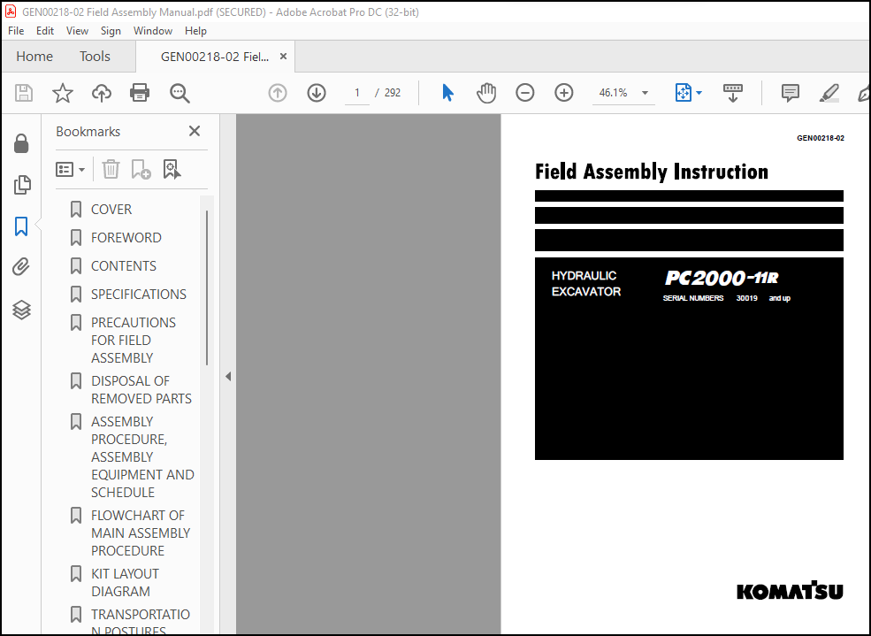
Komatsu PC2000-11R Hydraulic Excavator Field Assembly Instruction Manual GEN00218-02 – PDF DOWNLOAD
Komatsu PC2000-11R Hydraulic Excavator Field Assembly Instruction Manual GEN00218-02 – PDF DOWNLOAD
FILE DETAILS:
Komatsu PC2000-11R Hydraulic Excavator Field Assembly Instruction Manual GEN00218-02 – PDF DOWNLOAD
Language : English
Pages : 292
Downloadable : Yes
File Type : PDF
Size: 43.8 MB
IMAGES PREVIEW OF THE MANUAL:

DESCRIPTION:
Komatsu PC2000-11R Hydraulic Excavator Field Assembly Instruction Manual GEN00218-02 – PDF DOWNLOAD
SERIAL NUMBERS 30019 and up
FOREWORD:
Since this machine is large in size, it is divided into some units to meet
the transportation conditions and regulations applied to the transportation
route when shipped from our factory.
This manual describes how to assemble the units into the complete
machine in the field. We hope that this machine will display its quality
and you will use it safely according to the operation manual.
Many units are large in size and heavy in weight and may be handled
in a dangerous place or posture and many workers may have to work
together to sling them with cranes.
Accordingly, before starting the assembly work, the work supervisor is
required to hold a safety meeting to oblige the workers to put on protective
gear and appoint a work leader and a crane work signal man
and allot roles to all the workers for safe work.
In particular, the above meeting is more important when worker of different
languages and customs work together.
The following is a reference supervision system diagram.
TABLE OF CONTENTS:
Komatsu PC2000-11R Hydraulic Excavator Field Assembly Instruction Manual GEN00218-02 – PDF DOWNLOAD
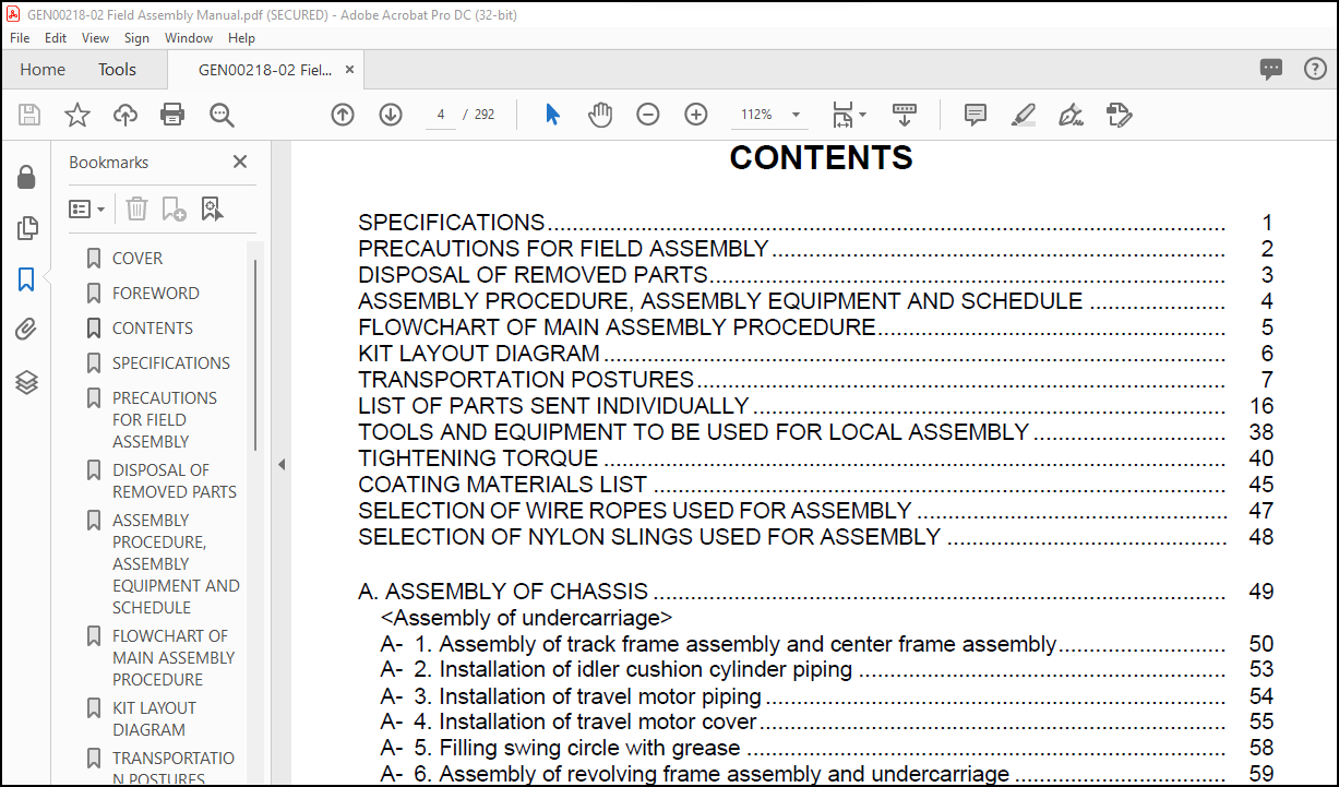
SPECIFICATIONS………………………………………………………………………………………………. 1
PRECAUTIONS FOR FIELD ASSEMBLY ………………………………………………………………. 2
DISPOSAL OF REMOVED PARTS……………………………………………………………………….. 3
ASSEMBLY PROCEDURE, ASSEMBLY EQUIPMENT AND SCHEDULE …………………. 4
FLOWCHART OF MAIN ASSEMBLY PROCEDURE……………………………………………….. 5
KIT LAYOUT DIAGRAM ………………………………………………………………………………………. 6
TRANSPORTATION POSTURES…………………………………………………………………………. 7
LIST OF PARTS SENT INDIVIDUALLY …………………………………………………………………. 16
TOOLS AND EQUIPMENT TO BE USED FOR LOCAL ASSEMBLY …………………………. 38
TIGHTENING TORQUE ………………………………………………………………………………………. 40
COATING MATERIALS LIST ……………………………………………………………………………….. 45
A. ASSEMBLY OF CHASSIS ……………………………………………………………………………….. 49
<Assembly of undercarriage>
A- 1. Assembly of track frame assembly and center frame assembly……………………… 50
A- 2. Installation of idler cushion cylinder piping ………………………………………………….. 53
A- 3. Installation of travel motor piping ……………………………………………………………….. 54
A- 4. Installation of travel motor cover………………………………………………………………… 55
A- 5. Filling swing circle with grease ………………………………………………………………….. 58
A- 6. Assembly of revolving frame assembly and undercarriage ……………………………. 59
A- 7. Installation of swing machinery (front) assembly (27t)
Installation of swing motor (front) assembly (32t) …………………………………………. 61
A- 8. Connection of swivel joint piping………………………………………………………………… 62
A- 9. Connection of swing circle grease piping ……………………………………………………. 63
<Assembly of upper structure>
A-10. Installation of hydraulic tank assembly ……………………………………………………….. 64
A-11. Installation of fuel tank assembly……………………………………………………………….. 69
A-12. Connection of fuel tank assembly piping and wiring……………………………………… 70
A-13. Installation of cab base assembly………………………………………………………………. 72
A-14. Installation of emergency escape ladder …………………………………………………….. 74
A-15. Installation of left floor assembly ……………………………………………………………….. 75
A-16. Connection of cab base assembly piping ……………………………………………………. 80
A-17. Connection of cab base assembly wiring ……………………………………………………. 83
A-18. Connection of left floor assembly heater piping……………………………………………. 90
<Coupling of power module>
A-19. Connection of left floor assembly wiring ……………………………………………………… 91
A-20. Installation of tail pipe and precleaner ………………………………………………………… 93
A-21. Installation of power module assembly……………………………………………………….. 95
A-22. Connection of suction piping …………………………………………………………………….. 97
A-23. Connection of oil cooler piping and pump drain piping………………………………….. 99
A-24. Connection of fan motor drain piping………………………………………………………….. 100
A-25. Installation of suction unit undercover ………………………………………………………… 101
A-26. Connection of delivery piping ……………………………………………………………………. 102
A-27. Connection of pilot piping and fan motor piping …………………………………………… 105
A-28. Connection of power module assembly fuel piping ………………………………………. 106
A-29. Connection of power module assembly air conditioner piping ……………………….. 108
A-30. Connection of power module assembly heater piping…………………………………… 109
A-31. Connection of power module assembly wiring …………………………………………….. 110
SELECTION OF WIRE ROPES USED FOR ASSEMBLY ………………………………………….. 47
SELECTION OF NYLON SLINGS USED FOR ASSEMBLY ……………………………………… 48
<Coupling of operator’s cab>
A-32. Installation of operator’s cab assembly ………………………………………………………. 114
A-33. Installation of rotary lamp (if equipped) ………………………………………………………. 118
A-34. Installation of Iridium antenna …………………………………………………………………… 120
A-35. Connection of operator’s cab assembly wiring…………………………………………….. 121
A-36. Connection of operator’s cab assembly hydraulic piping ………………………………. 124
A-37. Connection of operator’s cab assembly window washer hose……………………….. 126
A-38. Connection of operator’s cab assembly air conditioner piping ……………………….. 127
A-39. Connection of operator’s cab assembly heater piping ………………………………….. 129
A-40. Installation of operator’s cab rear floor assembly…………………………………………. 130
A-41. Installation of handrail around operator’s cab ……………………………………………… 131
<Coupling of exterior parts, counterweight, etc.>
A-42. Installation of track frame ladder ……………………………………………………………….. 132
A-43. Installation of power module side catwalk assemblies (right and left)…………….. 133
A-44. Installation of right floor assembly,
grease can cover assembly and center floor……………………………………………….. 134
A-45. Installation of fuel tank right catwalk assembly ……………………………………………. 136
A-46. Installation of fuel tank front catwalk assembly ……………………………………………. 137
A-47. Adjustment of exterior parts clearance……………………………………………………….. 138
A-48. Connection of grease reel piping ………………………………………………………………. 139
A-49. Installation of access ladder assembly……………………………………………………….. 140
A-50. Installation of counterweight assembly ………………………………………………………. 141
A-51. Installation of deformation preventing stoppers for catwalk assemblies
(left and right) on the side of power module ………………………………………………… 142
A-52. Installation of handrail on counterweight…………………………………………………….. 143
A-53. Installation of handrail clamps…………………………………………………………………… 144
A-54. Connection of fuel cut wire……………………………………………………………………….. 147
A-55. Connection of drain piping under power module………………………………………….. 148
A-56. Connection of battery wiring……………………………………………………………………… 149
<Starting of engine and inspection and servicing procedures>
A-57. Setting of hydraulic tank strainer……………………………………………………………….. 150
A-58. Starting engine, checking oil and coolant levels, bleeding air from each part,
and adjusting track ………………………………………………………………………………….. 151
A-59. Permanent tightening of swing circle bolt……………………………………………………. 166
A-60. Parts to be touched up after field assembly (chassis side) ……………………………. 167
A-61. Connection of engine heater connection port ……………………………………………… 168
A-62. Installation of optional harness………………………………………………………………….. 171
A-63. Installation of KomVision and rear lamp……………………………………………………… 172
A-64. Connection of emergency stop switch (if equipped) (at the right below power module)… 181
A-65. Connection of emergency stop switch (if equipped) (at the left side of ladder)…. 182
A-66. Installation of engine oil and PTO oil pipings ………………………………………………. 183
A-67. Installation of coolant piping……………………………………………………………………… 184
A-68. Installation of guard bracket (if equipped) …………………………………………………… 185
C. ASSEMBLY OF BACKHOE………………………………………………………………………………. 187
<Coupling of boom>
C- 1. Installation of boom cylinder……………………………………………………………………… 188
C- 2. Installation of boom cylinder hoses ……………………………………………………………. 190
C- 3. Assembly of boom sub assembly………………………………………………………………. 191
C- 4. Installation of boom assembly…………………………………………………………………… 196
C- 5. Installation of boom cylinder head side ………………………………………………………. 198
C- 6. Installation of hoses between boom and chassis …………………………………………. 200
<Coupling of arm>
C- 7. Installation of arm assembly ……………………………………………………………………… 201
C- 8. Installation of arm cylinder………………………………………………………………………… 204
C- 9. Connection of hoses between boom and arm ……………………………………………… 205
C-10. Connection of auto grease piping………………………………………………………………. 206
C-11. Connection of wiring between boom and chassis ………………………………………… 207
<Coupling of bucket>
C-12. Installation of bucket assembly …………………………………………………………………. 208
C-13. Installation of bucket link ………………………………………………………………………….. 211
C-14. Bleeding air from cylinders ……………………………………………………………………….. 213
C-15. Parts to be touched up after field assembly (work equipment side)………………… 217
C-16. Bleeding air from auto grease circuit………………………………………………………….. 218
M. INSPECTION AND SERVICING PROCEDURES AFTER ASSEMBLY…………………… 221
M- 1. Inspection of oil levels and coolant levels and
using standard of fuel and lubricant …………………………………………………………… 222
M- 2. Flushing of hydraulic circuit………………………………………………………………………. 224
M- 3. Releasing residual pressure from hydraulic circuit……………………………………….. 233
M- 4. Releasing residual pressure from HIC circuit and check of
gas pressure in HIC accumulator………………………………………………………………. 234
M- 5. Charging air conditioner with refrigerant ……………………………………………………. 235
M- 6. Installed angles of mirrors ………………………………………………………………………… 238
M- 7. Installed angles of lights…………………………………………………………………………… 241
M- 8. Method for starting up KOMTRAX terminal and default setting of
KOMTRAX Plus controller………………………………………………………………………… 244
PC2000-11R Main pump air bleeding check sheet ………………………………………………….. 258
FIELD ASSEMBLY INSPECTION REPORT (BACKHOE)
More products