$42
Komatsu PC2000-8 Hydraulic Excavator Shop Manual SEN01607-31 – PDF DOWNLOAD
Komatsu PC2000-8 Hydraulic Excavator Shop Manual SEN01607-31 – PDF DOWNLOAD
FILE DETAILS:
Komatsu PC2000-8 Hydraulic Excavator Shop Manual SEN01607-31 – PDF DOWNLOAD
Language : English
Pages : 1550
Downloadable : Yes
File Type : PDF
Size: 98.4 MB
IMAGES PREVIEW OF THE MANUAL:
DESCRIPTION:
Komatsu PC2000-8 Hydraulic Excavator Shop Manual SEN01607-31 – PDF DOWNLOAD
- The Komatsu PC2000-8 Hydraulic Excavator Shop Manual is a comprehensive guide that provides detailed information and instructions for the maintenance, repair, and overhaul of the Komatsu PC2000-8 hydraulic excavator. This manual is designed to help users understand the various systems and components of the excavator, and provides step-by-step instructions for performing routine maintenance tasks, as well as more complex repair and overhaul procedures.
- The manual is organized into sections that correspond to the various systems and components of the excavator, including the engine, hydraulic system, electrical system, undercarriage, and more. Within each section, the manual provides detailed information about the components, including specifications, procedures for disassembly and reassembly, and troubleshooting tips. The manual also includes exploded view illustrations that show the relationship between the parts, making it easier to understand the components and how they work together.
- One of the key benefits of the Komatsu PC2000-8 Hydraulic Excavator Shop Manual is its focus on preventative maintenance. The manual provides detailed information about the recommended maintenance procedures for each component, as well as guidelines for monitoring the health of the excavator and addressing potential issues before they become major problems. This can help users extend the lifespan of the excavator, minimize downtime, and reduce repair costs.
- In addition to providing information about the excavator itself, the Komatsu PC2000-8 Hydraulic Excavator Shop Manual also includes important safety information, including guidelines for working around the excavator, handling hazardous materials, and using the excavator safely and efficiently.
- Overall, the Komatsu PC2000-8 Hydraulic Excavator Shop Manual is a valuable resource for anyone who needs to maintain, repair, or overhaul the Komatsu PC2000-8 hydraulic excavator. With its clear and concise language, step-by-step instructions, and detailed illustrations, this manual is an essential tool for anyone who is involved in the maintenance and repair of this important piece of heavy machinery.
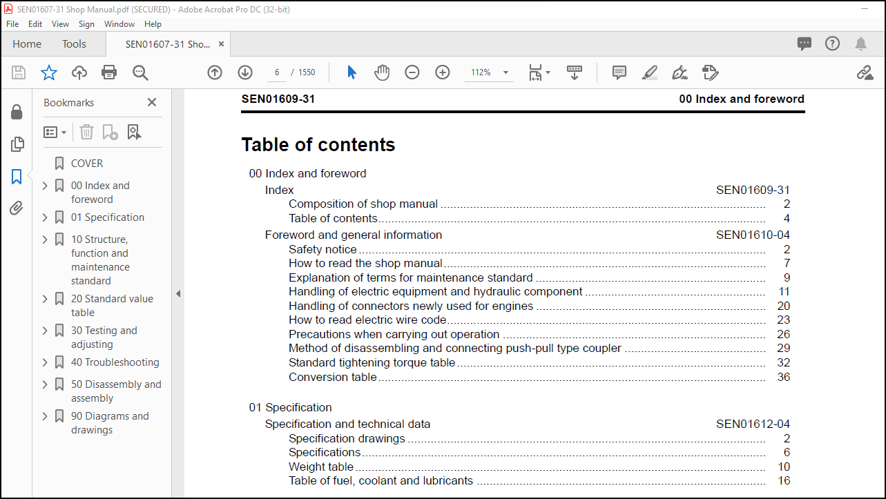
TABLE OF CONTENTS:
Komatsu PC2000-8 Hydraulic Excavator Shop Manual SEN01607-31 – PDF DOWNLOAD
COVER……………………………………………………………………………………………….. 1
00 Index and foreword…………………………………………………………………………………. 3
Index……………………………………………………………………………………………. 3
Composition of shop manual……………………………………………………………………… 4
Table of contents……………………………………………………………………………… 6
Foreword and general information……………………………………………………………………. 19
Safety notice…………………………………………………………………………………. 20
How to read the shop manual…………………………………………………………………….. 25
Explanation of terms for maintenance standard…………………………………………………….. 27
Handling of electric equipment and hydraulic component…………………………………………….. 29
Handling of connectors newly used for engines…………………………………………………….. 38
How to read electric wire code………………………………………………………………….. 41
Precautions when carrying out operation………………………………………………………….. 44
Method of disassembling and connecting push-pull type coupler………………………………………. 47
Standard tightening torque table………………………………………………………………… 50
Conversion table………………………………………………………………………………. 54
01 Specification……………………………………………………………………………………… 61
Specification and technical data……………………………………………………………………. 61
Specification drawings…………………………………………………………………………. 62
Specifications………………………………………………………………………………… 66
Weight table………………………………………………………………………………….. 70
Table of fuel, coolant and lubricants……………………………………………………………. 76
10 Structure, function and maintenance standard………………………………………………………….. 79
Engine and cooling system………………………………………………………………………….. 79
Radiator and oil cooler………………………………………………………………………… 80
PTO………………………………………………………………………………………….. 82
PTO lubrication system…………………………………………………………………………. 84
Power train………………………………………………………………………………………. 87
Power train…………………………………………………………………………………… 88
Swing machinery……………………………………………………………………………….. 90
Swing circle………………………………………………………………………………….. 92
Final drive…………………………………………………………………………………… 94
Sprocket……………………………………………………………………………………… 96
Undercarriage and frame……………………………………………………………………………. 99
Track frame…………………………………………………………………………………… 100
Idler………………………………………………………………………………………… 102
Carrier roller………………………………………………………………………………… 104
Track roller………………………………………………………………………………….. 105
Track shoe……………………………………………………………………………………. 106
HIC system……………………………………………………………………………………. 111
Hydraulic system, Part 1…………………………………………………………………………… 119
Hydraulic piping drawing……………………………………………………………………….. 122
Hydraulic tank………………………………………………………………………………… 126
Oil cooler……………………………………………………………………………………. 128
Line oil filter……………………………………………………………………………….. 130
Pilot oil filter………………………………………………………………………………. 131
Return oil filter……………………………………………………………………………… 132
Motor drain oil filter…………………………………………………………………………. 133
Pump drain filter……………………………………………………………………………… 134
Accumulator…………………………………………………………………………………… 135
Travel junction valve………………………………………………………………………….. 137
Solenoid valve………………………………………………………………………………… 140
Hydraulic cylinder…………………………………………………………………………….. 148
Greasing system……………………………………………………………………………….. 152
Center swivel joint……………………………………………………………………………. 162
Hydraulic ladder system………………………………………………………………………… 163
Service center system………………………………………………………………………….. 168
Hydraulic system, Part 2…………………………………………………………………………… 175
Hydraulic system, Part 2……………………………………………………………………….. 176
Control valve……………………………………………………………………………… 176
Electronic OLSS system……………………………………………………………………… 204
Swing motor……………………………………………………………………………….. 208
Cooling fan motor (For radiator and oil cooler)……………………………………………….. 216
Cooling fan pump…………………………………………………………………………… 222
Hydraulic system, Part 3…………………………………………………………………………… 237
Travel motor………………………………………………………………………………….. 238
Hydraulic pump………………………………………………………………………………… 250
PPC valve…………………………………………………………………………………….. 270
Variable back pressure valve……………………………………………………………………. 282
Suction selector valve…………………………………………………………………………. 286
PPC cut-off valve……………………………………………………………………………… 290
Work equipment……………………………………………………………………………………. 299
Work equipment………………………………………………………………………………… 300
Dimensions of work equipment……………………………………………………………………. 304
Cab and its attachments……………………………………………………………………………. 309
Air conditioner piping…………………………………………………………………………. 310
Cab………………………………………………………………………………………….. 311
Electrical system…………………………………………………………………………………. 315
Engine control………………………………………………………………………………… 316
Electrical control system………………………………………………………………………. 327
Monitor system………………………………………………………………………………… 369
Sensor……………………………………………………………………………………….. 397
ORBCOMM terminal………………………………………………………………………………. 409
20 Standard value table……………………………………………………………………………….. 411
Standard service value table……………………………………………………………………….. 411
Standard service value table for engine………………………………………………………….. 412
Standard service value table for chassis (Backhoe specification)……………………………………. 413
Standard service value table for chassis (Loading shovel specification)……………………………… 424
30 Testing and adjusting………………………………………………………………………………. 437
Testing and adjusting, Part 1………………………………………………………………………. 437
Tools for testing, adjusting, and troubleshooting…………………………………………………. 439
Measuring engine speed…………………………………………………………………………. 442
Testing air boost pressure……………………………………………………………………… 443
Testing exhaust temperature…………………………………………………………………….. 444
Testing exhaust color………………………………………………………………………….. 445
Adjusting valve clearance………………………………………………………………………. 447
Testing compression pressure……………………………………………………………………. 449
Testing blow-by pressure……………………………………………………………………….. 451
Testing engine oil pressure…………………………………………………………………….. 452
Handling fuel system parts……………………………………………………………………… 453
Releasing residual pressure in fuel system……………………………………………………….. 453
Testing fuel pressure………………………………………………………………………….. 454
Reduced cylinder mode operation…………………………………………………………………. 455
No-injection cranking………………………………………………………………………….. 455
Testing leakage from pressure limiter and return rate from injector…………………………………. 456
Bleeding air from fuel circuit………………………………………………………………….. 459
Bleeding air from fuel circuit (lowgrade fuel specification)……………………………………….. 463
Testing fuel system for leakage…………………………………………………………………. 465
Testing and adjusting alternator belt tension…………………………………………………….. 466
Testing and adjusting air conditioner compressor belt tension………………………………………. 467
Handling controller high-voltage circuit…………………………………………………………. 468
Testing and adjusting, Part 2………………………………………………………………………. 471
Testing swing circle bearing clearance…………………………………………………………… 473
Remaining pressure relief from HIC circuit……………………………………………………….. 474
Gas filling in HIC circuit accumulator…………………………………………………………… 475
Bleeding air from HIC circuit and supplying oil to it……………………………………………… 478
Testing and adjusting track shoe tension…………………………………………………………. 482
Testing and adjusting work equipment, swing and travel circuit oil pressures…………………………. 486
Testing and adjusting control circuit oil pressure (output pressure of self pressure reducing valve)……. 490
Testing and adjusting main pump control signal……………………………………………………. 492
Measuring fan speed……………………………………………………………………………. 495
Measuring fan pump EPC solenoid current………………………………………………………….. 496
Measuring fan pump EPC solenoid valve output pressure……………………………………………… 497
Oil pressure measuring points for pump discharge pressure or jet sensor differential pressure………….. 499
Measuring PPC valve output pressure……………………………………………………………… 500
Measuring solenoid valve outlet pressure…………………………………………………………. 504
Adjusting work equipment and swing PPC valve……………………………………………………… 506
Testing and adjusting travel deviation…………………………………………………………… 507
Testing work equipment hydraulic drift cause portion………………………………………………. 509
Testing oil leakage……………………………………………………………………………. 510
Remaining pressure relief from hydraulic circuit………………………………………………….. 513
Air bleeding from each component………………………………………………………………… 514
Testing and adjusting auto grease system…………………………………………………………. 520
Adjusting mirrors……………………………………………………………………………… 523
Testing and adjusting clearance of hydraulic ladder proximity switch………………………………… 525
Testing and adjusting position of hydraulic ladder position sensor plate…………………………….. 527
Testing and adjusting clearance to service arm proximity switch…………………………………….. 528
Testing and adjusting, Part 3………………………………………………………………………. 531
Special functions of machine monitor…………………………………………………………….. 532
Handling controller voltage circuit……………………………………………………………… 587
Testing and adjusting, Part 4………………………………………………………………………. 589
VHMS controller initial setting procedure………………………………………………………… 590
Precautions for replacing VHMS controller………………………………………………………… 609
Preparation work for troubleshooting of electrical system………………………………………….. 615
Pm-clinic service……………………………………………………………………………… 617
Measurement procedure………………………………………………………………………….. 618
40 Troubleshooting……………………………………………………………………………………. 637
Failure code table and fuse locations……………………………………………………………….. 637
Failure code table…………………………………………………………………………….. 638
Before carrying out troubleshooting of electrical system…………………………………………… 645
General information on troubleshooting………………………………………………………………. 653
Points to remember when troubleshooting………………………………………………………….. 654
Sequence of events in troubleshooting……………………………………………………………. 655
Checks before troubleshooting…………………………………………………………………… 656
Classification and procedures of troubleshooting………………………………………………….. 657
Connection table for connector pin numbers……………………………………………………….. 661
T- branch box and T- branch adapter table………………………………………………………… 697
Troubleshooting by failure code, Part 1……………………………………………………………… 701
Failure code [0410KA] Fuel LV. Sensor Failure…………………………………………………….. 704
Failure code [0410KB] Fuel LV. Sensor Failure…………………………………………………….. 706
Failure code [6014NX] Hydraulic Oil Filter Clogging (or change of VHMS-LED display from n5 to 51)………. 708
Failure code [8800ZG] Auto grease abnormally……………………………………………………… 709
Failure code [7@HAZL] VR1/P1F Relief Press Abnormality…………………………………………….. 710
Failure code [7@HBZL] VL1/P1R Relief Press Abnormality…………………………………………….. 711
Failure code [7@HCZL] VR2/P2F Relief Press Abnormality…………………………………………….. 712
Failure code [7@HDZL] VL2/P2R Relief Press Abnormality…………………………………………….. 714
Failure code [AA10NX] Aircleaner Clogging………………………………………………………… 716
Failure code [AB00KE] Charge Voltage Low…………………………………………………………. 718
Failure code [aB00KE] Low Upper ALR Charge Voltage (or change of VHMS-LED display from n9 to 11)……….. 720
Failure code [B@BAZG] Eng. Oil Press. Low………………………………………………………… 722
Failure code [B@BAZK] Eng. Oil Level Low…………………………………………………………. 724
Failure code [B@BCNS] Eng. Water Overheat………………………………………………………… 726
Failure code [B@BCZK] Eng. Water Lvl Low…………………………………………………………. 728
Failure code [B@CBNS] PTO Oil Overheat (or change of VHMS-LED display from n5 to 61)………………….. 730
Failure code [B@HANS] Hydr. Oil Overheat…………………………………………………………. 732
Failure code [B@HAZK] Low Hydraulic Oil Level (or change of VHMSLED display from n5 to 52)…………….. 734
Failure code [CA111] ECM Critical Internal Failure………………………………………………… 736
Failure code [CB111] ECM Critical Internal Failure………………………………………………… 738
Failure code [CA115] Eng. Ne and Bkup Speed Sens Error…………………………………………….. 740
Failure code [CB115] Eng. Ne and Bkup Speed Sens Error…………………………………………….. 741
Failure code [CA122] Chg Air Press Sensor High Error………………………………………………. 742
Failure code [CA123] Chg Air Press Sensor Low Error……………………………………………….. 744
Failure code [CA131] Throttle Sensor High Error…………………………………………………… 746
Failure code [CA132] Throttle Sensor Low Error……………………………………………………. 748
Failure code [CA135] Eng Oil Press Sensor High Error………………………………………………. 750
Failure code [CA141] Eng Oil Press Sensor Low Error……………………………………………….. 752
Failure code [CA144] Coolant Temp Sens High Error…………………………………………………. 754
Failure code [CA145] Coolant Temp Sens Low Error………………………………………………….. 756
Failure code [CA153] Chg Air Temp Sensor High Error……………………………………………….. 758
Failure code [CA154] Chg Air Temp Sensor Low Error………………………………………………… 760
Failure code [CA187] Sens Supply 2 Volt Low Error…………………………………………………. 762
Failure code [CB187] Sens Supply 2 Volt Low Error…………………………………………………. 762
Failure code [CA212] Eng Oil Temp Sensor High Error……………………………………………….. 764
Failure code [CA213] Eng Oil Temp Sensor Low Error………………………………………………… 766
Troubleshooting by failure code, Part 2……………………………………………………………… 769
Failure code [CA221] Ambient Press Sens High Error………………………………………………… 772
Failure code [CA222] Ambient Press Sens Low Error…………………………………………………. 774
Failure code [CA227] Sens Supply 2 Volt High Error………………………………………………… 776
Failure code [CB227] Sens Supply 2 Volt High Error………………………………………………… 778
Failure code [CA234] Eng Over Speed……………………………………………………………… 780
Failure code [CA238] Ne Speed Sens Supply Volt Error………………………………………………. 782
Failure code [CB238] Ne Speed Sens Supply Volt Error………………………………………………. 784
Failure code [CA263] Fuel Temp Sensor High Error………………………………………………….. 786
Failure code [CB263] Fuel Temp Sensor High Error………………………………………………….. 788
Failure code [CA265] Fuel Temp Sensor Low Error…………………………………………………… 789
Failure code [CB265] Fuel Temp Sensor Low Error…………………………………………………… 789
Failure code [CA271] IMV/PCV1 Short Error………………………………………………………… 790
Failure code [CB271] IMV/PCV1 Short Error………………………………………………………… 792
Failure code [CA272] IMV/PCV1 Open Error…………………………………………………………. 794
Failure code [CB272] IMV/PCV1 Open Error…………………………………………………………. 796
Failure code [CA273] PCV2 Short Error……………………………………………………………. 798
Failure code [CB273] PCV2 Short Error……………………………………………………………. 800
Failure code [CA274] PCV2 Open Error…………………………………………………………….. 802
Failure code [CB274] PCV2 Open Error…………………………………………………………….. 804
Failure code [CA322] Inj #1(L/B#1) Open/Short Error……………………………………………….. 806
Failure code [CA323] Inj #5(L/B#5) Open/Short Error……………………………………………….. 808
Failure code [CA324] Inj #3(L/B#3) Open/Short Error……………………………………………….. 810
Failure code [CA325] Inj #6(L/B#6) Open/Short Error……………………………………………….. 812
Failure code [CA331] Inj #2(L/B#2) Open/Short Error……………………………………………….. 814
Failure code [CA332] Inj #4(L/B#4) Open/Short Error……………………………………………….. 816
Failure code [CA342] Calibration Code Incompatibility……………………………………………… 818
Failure code [CB342] Calibration Code Incompatibility……………………………………………… 818
Failure code [CA351] Injectors Drive Circuit Error………………………………………………… 820
Failure code [CB351] Injectors Drive Circuit Error………………………………………………… 822
Failure code [CA352] Sens Supply 1 Volt Low Error…………………………………………………. 824
Failure code [CB352] Sens Supply 1 Volt Low Error…………………………………………………. 824
Failure code [CA386] Sens Supply 1 Volt High Error………………………………………………… 826
Failure code [CB386] Sens Supply 1 Volt High Error………………………………………………… 828
Failure code [CA441] Battery Voltage Low Error……………………………………………………. 830
Failure code [CB441] Battery Voltage Low Error……………………………………………………. 830
Failure code [CA442] Battery Voltage High Error…………………………………………………… 831
Failure code [CB442] Battery Voltage High Error…………………………………………………… 831
Failure code [CA449] Rail Press Very High Error…………………………………………………… 832
Failure code [CB449] Rail Press Very High Error…………………………………………………… 832
Troubleshooting by failure code, Part 3……………………………………………………………… 835
Failure code [CA451] Rail Press Sensor High Error…………………………………………………. 838
Failure code [CB451] Rail Press Sensor High Error…………………………………………………. 840
Failure code [CA452] Rail Press Sensor Low Error………………………………………………….. 842
Failure code [CB452] Rail Press Sensor Low Error………………………………………………….. 842
Failure code [CA553] Rail Press High Error……………………………………………………….. 843
Failure code [CB553] Rail Press High Error……………………………………………………….. 844
Failure code [CA554] Rail Press Sensor In Range Error……………………………………………… 845
Failure code [CB554] Rail Press Sensor In Range Error……………………………………………… 845
Failure code [CA559] Rail Press Low Error………………………………………………………… 846
Failure code [CB559] Rail Press Low Error………………………………………………………… 850
Failure code [CA689] Eng Ne Speed Sensor Error……………………………………………………. 854
Failure code [CB689] Eng Ne Speed Sensor Error……………………………………………………. 856
Failure code [CA691] Intake Air Temp Sens High Error………………………………………………. 858
Failure code [CA692] Intake Air Temp Sens Low Error……………………………………………….. 860
Failure code [CA731] Eng Bkup Speed Sens Phase Error………………………………………………. 861
Failure code [CB731] Eng Bkup Speed Sens Phase Error………………………………………………. 861
Failure code [CA757] All Persistent Data Lost Error……………………………………………….. 862
Failure code [CB757] All Persistent Data Lost Error……………………………………………….. 862
Failure code [CA778] Eng Bkup Speed Sensor Error………………………………………………….. 864
Failure code [CB778] Eng Bkup Speed Sensor Error………………………………………………….. 866
Failure code [CA781] CEN Communication Error……………………………………………………… 868
Failure code [CB781] CEN Communication Error……………………………………………………… 870
Failure code [CA1257] Harness Key Error………………………………………………………….. 872
Failure code [CB1257] Harness Key Error………………………………………………………….. 873
Failure code [CB1548] Inj #7(R/B#1) Open/Short Error………………………………………………. 874
Failure code [CB1549] Inj #8(R/B#2) Open/Short Error………………………………………………. 876
Failure code [CB1551] Inj #10(R/B#4) Open/Short Error……………………………………………… 878
Failure code [CB1552] Inj #11(R/B#5) Open/Short Error……………………………………………… 880
Failure code [CB1553] Inj #12(R/B#6) Open/Short Error……………………………………………… 882
Failure code [CB1622] Inj #9(R/B#3) Open/Short Error………………………………………………. 884
Failure code [CA1633] KOMNET Data link Time out Error……………………………………………… 886
Failure code [CA2185] Throt Sens Sup Volt High Error………………………………………………. 888
Failure code [CA2186] Throt Sens Sup Volt Low Error……………………………………………….. 890
Failure code [CA2249] Rail Press Very Low Error…………………………………………………… 891
Failure code [CB2249] Rail Press Very Low Error…………………………………………………… 891
Failure code [CA2555] Grid Heater Relay Volt Low Error…………………………………………….. 892
Failure code [CA2556] Grid Heater Relay Volt High Error……………………………………………. 894
Troubleshooting by failure code, Part 4……………………………………………………………… 897
Failure code [D110KB] Battery Relay Drive S/C…………………………………………………….. 900
Failure code [D163KB] Flash Light Relay S/C………………………………………………………. 902
Failure code [D195KA] Step Light Relay Disc………………………………………………………. 904
Failure code [D195KY] Step Light Relay S/C……………………………………………………….. 906
Failure code [D1E9KB] Wiper Drive Relay 1 S/C…………………………………………………….. 908
Failure code [D1EAKB] Wiper Drive Relay 2 S/C…………………………………………………….. 910
Failure code [D1EBKB] Lower Wiper Brake Relay Short Circuit………………………………………… 912
Failure code [D1ECKB] Upper Wiper Brake Relay Short Circuit………………………………………… 914
Failure code [DA22KK] Pump 1 Solenoid Power Low Error……………………………………………… 916
Failure code [dA22KK] Pump 2 Solenoid Power Low Error……………………………………………… 918
Failure code [DA25KP] Pump 1 Sens Supply Vol Low Error…………………………………………….. 920
Failure code [dA25KP] Pump 2 Sens Supply Vol Low Error…………………………………………….. 922
Failure code [DA26KP] 5V Sensor 2 Power Abnormality……………………………………………….. 924
Failure code [DA29KQ] Pump 1 Model Select Abnormality……………………………………………… 926
Failure code [dA29KQ] Pump 2 Model Select Abnormality……………………………………………… 928
Failure code [DA2RMC] CAN Discon (Pump 1 Con Detected)…………………………………………….. 930
Failure code [dA2RMC] CAN Discon (Pump 2 Con Detected)…………………………………………….. 932
Failure code [DAFRMC] CAN Discon (Monitor Detected)……………………………………………….. 934
Failure code [DA2TMC] Pump Comm. ECM Child Abnormality…………………………………………….. 936
Failure code [DBB0KK] VHMS Source Voltage Error (or change of VHMS-LED display from n9 to 01)………….. 938
Failure code [DBB0KQ] VHMS Connector Mismatch (or change of VHMS-LED display from nF to 11)……………. 940
Failure code [DBB5KP] VHMS 5V source sys Error (or change of VHMSLED display from n9 to 04)……………. 942
Failure code [DBB6KP] VHMS 24V source sys Error (or change of VHMS-LED display from n9 to 02)………….. 944
Failure code [DBBQKR] KOM-NET/c error (or change of VHMS-LED display from n8 to 02)…………………… 946
Failure code [DGE5KX] Ambient Air Temp Sensor Failure (or change of VHMS-LED display from n4 to 01)…….. 948
Failure code [DGH2KB] Hydr. Oil Temp. Sensor S/C………………………………………………….. 950
Failure code [DGT3KZ] PTO Temp Sensor Failure (or change of VHMSLED display from n5 to 01)…………….. 952
Troubleshooting by failure code, Part 5……………………………………………………………… 955
Failure code [DGT5KA] Exhaust Temp. Sensor LBF Failure (or change of VHMS-LED display from n3 to 12)……. 958
Failure code [dGT5KA] Exhaust Temp. Sensor LBR Failure (or change of VHMS-LED display from n3 to 22)……. 960
Failure code [DGT5KB] Exhaust Temp. Sensor LBF Failure (or change of VHMS-LED display from n3 to 11)……. 962
Failure code [dGT5KB] Exhaust Temp. Sensor LBR Failure (or change of VHMS-LED display from n3 to 21)……. 964
Failure code [DGT6KA] Exhaust Temp. Sensor RBF Failure (or change of VHMS-LED display from n3 to 24)……. 966
Failure code [dGT6KA] Exhaust Temp. Sensor RBR Failure (or change of VHMS-LED display from n3 to 26)……. 968
Failure code [DGT6KB] Exhaust Temp. Sensor RBF Failure (or change of VHMS-LED display from n3 to 23)……. 970
Failure code [dGT6KB] Exhaust Temp. Sensor RBR Failure (or change of VHMS-LED display from n3 to 26)……. 972
Failure code [DH25KX] VR1/P1F J/S Dif Press Sensor Abnormality……………………………………… 974
Failure code [DH26KX] VL1/P1R J/S Dif Press Sensor Abnormality……………………………………… 976
Failure code [DH27KX] VR2/P2F J/S Dif Press Sensor Abnormality……………………………………… 978
Failure code [DH28KX] VL2/P2R J/S Dif Press Sensor Abnormality……………………………………… 980
Failure code [DHE5KB] Blowby Pres. Sensor Failure (or change of VHMS-LED display from n3 to 32)………… 982
Failure code [DHE5KY] Blowby Pres. Sensor Failure (or change of VHMS-LED display from n3 to 31)………… 984
Failure code [DHH2KA] Hydraulic oil filter Sensor Failure (or change of VHMS-LED display from n5 to 53)…. 986
Failure code [DHPEKX] VR1/P1F Pump P. Sensor Abnormality…………………………………………… 988
Failure code [DHPFKX] VL1/P1R Pump P. Sensor Abnormality…………………………………………… 990
Failure code [DHPGKX] VR2/P2F Pump P. Sensor Abnormality…………………………………………… 992
Failure code [DHPHKX] VL2/P2R Pump P. Sensor Abnormality…………………………………………… 994
Failure code [DHPSKX] Auto Grease Press Sensor Abnormality…………………………………………. 996
Failure code [DHPTKX] Fan(RAD) Pump P. Sensor Open Circuit…………………………………………. 998
Failure code [DHPUKX] Fan(O/C) Pump P. Sensor Open Circuit………………………………………….1000
Failure code [DHS3KX] Arm Dig PPC Press Sensor Abnormality………………………………………….1002
Failure code [DHS4KX] Bucket Curl PPC Press Sensor Abnormality………………………………………1004
Failure code [DHS8KX] Boom Raise PPC Press Sensor Abnormality……………………………………….1006
Failure code [DHS9KX] Boom Lower PPC Press Sensor Abnormality……………………………………….1008
Failure code [DHSAKX] Swing Right PPC Press Sensor Abnormality………………………………………1010
Failure code [DHSBKX] Swing Left PPC Press Sensor Abnormality……………………………………….1012
Failure code [DHSCKX] Arm Dump PPC Press Sensor Abnormality…………………………………………1014
Failure code [DHSDKX] Bucket Dump PPC Press Sensor Abnormality………………………………………1016
Troubleshooting by failure code, Part 6………………………………………………………………1019
Failure code [DUM3KB] Auto Grease Caution LED Short Circuit…………………………………………1021
Failure code [DUM4KB] FAN Reverse LED Short Circuit………………………………………………..1022
Failure code [DV20KB] Travel Alarm S/C……………………………………………………………1023
Failure code [DW41KA] Swing Priority Sol Open Circuit………………………………………………1025
Failure code [DW41KB] Swing Priority Sol Short Circuit……………………………………………..1027
Failure code [DW45KA] Swing Brake Sol. Disc……………………………………………………….1029
Failure code [DW45KB] Swing Brake Sol. S/C………………………………………………………..1032
Failure code [DW91KA] Straight-Travel Sol. Disc……………………………………………………1034
Failure code [DW91KB] Straight-Travel Sol. S/C…………………………………………………….1036
Failure code [DW4XKA] Bucket Curl Hi Cancel Sol. Disc………………………………………………1038
Failure code [DW4XKB] Bucket Curl Hi Cancel Sol. S/C……………………………………………….1039
Failure code [DW7BKA] Fan Motor (RAD) Reverse Sol Open Circuit………………………………………1040
Failure code [DW7BKB] Fan Motor (RAD) Reverse Sol. S/C……………………………………………..1042
Failure code [DW7HKA] Fan Motor(O/C) Reverse Sol Open Circuit……………………………………….1044
Failure code [DW7HKB] Fan Motor(O/C) Reverse Sol Short Circuit………………………………………1046
Failure code [DWA3KA] Arm throttle Valve/L Sol Open Circuit…………………………………………1048
Failure code [DWA3KB] Arm throttle Valve/L Sol Short Circuit………………………………………..1050
Failure code [DWA4KA] Arm throttle Valve/R Sol Open Circuit…………………………………………1052
Failure code [DWA4KB] Arm throttle Valve/R Sol Short Circuit………………………………………..1054
Failure code [DWA5KA] Auto Grease Sol Open Circuit…………………………………………………1056
Failure code [DWA5KB] Auto Grease Sol Short Circuit………………………………………………..1058
Failure code [DWA6KA] Boom throttle Valve Sol Open Circuit………………………………………….1059
Failure code [DWA6KB] Boom throttle Valve Sol Short Circuit…………………………………………1061
Failure code [DWK0KA] 2-stage Relief Sol. Disc…………………………………………………….1063
Failure code [DWK0KB] 2-stage Relief Sol. S/C……………………………………………………..1065
Failure code [DWK2KA] Back Press Comp Valve Sol Open Circuit………………………………………..1066
Failure code [DWK2KB] Back Press Comp Valve Sol Short Circuit……………………………………….1067
Troubleshooting by failure code, Part 7………………………………………………………………1069
Failure code [DWN5KA] Fan(RAD) Pump EPC Sol Open Circuit……………………………………………1071
Failure code [DWN5KB] Fan(RAD) Pump EPC Sol Short Circuit…………………………………………..1072
Failure code [DWNCKA] Fan(O/C) Pump EPC Sol Open Circuit……………………………………………1073
Failure code [DWNCKB] Fan(O/C) Pump EPC Sol Short Circuit…………………………………………..1074
Failure code [DXAAKA] P1F EPC Sol Disc……………………………………………………………1076
Failure code [DXAAKB] P1F EPC Sol S/C…………………………………………………………….1078
Failure code [DXABKA] P1R Pump EPC Sol. Disc………………………………………………………1080
Failure code [DXABKB] P1R Pump EPC Sol. S/C……………………………………………………….1082
Failure code [DXACKA] P2F Pump EPC Sol. Disc………………………………………………………1084
Failure code [DXACKB] P2F Pump EPC Sol. S/C……………………………………………………….1086
Failure code [DXADKA] P2R Pump EPC Sol. Disc………………………………………………………1088
Failure code [DXADKB] P2R Pump EPC Sol. S/C……………………………………………………….1090
Failure code [DY2CKB] Washer Drive S/C……………………………………………………………1092
Failure code [DY20MA] Low Wiper Working Abnormality………………………………………………..1094
Failure code [DY2FMA] Upper Wiper Working Abnormality………………………………………………1097
Failure code [F@BBZL] High Blowby Pressure (or change of VHMS-LED display from n3 to 38)……………….1100
Failure code [F@BYNR] Very High LBF CYL Exhaust Temp (or change of VHMS-LED display from n3 to 62)………1102
Failure code [f@BYNR] Very High LBR CYL Exhaust Temp (or change of VHMS-LED display from n3 to 72)………1104
Failure code [F@BYNS] High LBF CYL Exhaust Temp (or change of VHMS-LED display from n3 to 61)…………..1106
Failure code [f@BYNS] High LBR CYL Exhaust Temp (or change of VHMS-LED display from n3 to 71)…………..1108
Failure code [F@BZNR] Very High RBF CYL Exhaust Temp (or change of VHMS-LED display from n3 to 82)………1110
Failure code [f@BZNR] Very High RBR CYL Exhaust Temp (or change of VHMS-LED display from n3 to 92)………1112
Failure code [F@BZNS] High RBF CYL Exhaust Temp (or change of VHMS-LED display from n3 to 81)…………..1114
Failure code [f@BZNS] High RBR CYL Exhaust Temp (or change of VHMS-LED display from n3 to 91)…………..1116
Failure code [LA10ZL] RAD system fan pump relief pressure high error…………………………………1118
Failure code [LA20ZL] O/C system pump relief pressure high error…………………………………….1120
Troubleshooting of electrical system (E-mode)…………………………………………………………1123
Before carrying out troubleshooting of electrical system……………………………………………1125
Contents of troubleshooting table………………………………………………………………..1132
E-1 When starting switch is turned ON, machine monitor displays nothing………………………………1134
E-2 When starting switch turned ON (before starting engine), basic check item lights up………………..1136
E-3 Engine does not start (Engine does not turn)…………………………………………………..1138
E-4 Auto-decelerator does not operate…………………………………………………………….1142
E-5 Automatic warm-up system does not operate……………………………………………………..1143
E-6 Preheater does not work……………………………………………………………………..1144
E-7 Whole work equipment, swing operation and machine travel operation are disabled……………………1146
E-8 Machine push-up function does not work………………………………………………………..1148
E-9 Boom shockless function cannot be released…………………………………………………….1150
E-10 Machine monitor does not display some items…………………………………………………..1152
E-11 Contents of display by machine monitor are different from applicable machine……………………..1153
E-12 Fuel level monitor lights up in red while engine is running…………………………………….1154
E-13 Hydraulic oil temperature gauge does not indicate normally……………………………………..1155
E-14 Fuel level gauge does not indicate normally…………………………………………………..1156
E-15 Swing lock monitor does not indicate normally…………………………………………………1158
E-16 Machine monitor display anything even when operated on monitor switch section…………………….1160
E-17 Wiper does not work………………………………………………………………………..1161
E-18 Monitoring function does not display “Travel” normally…………………………………………1168
E-19 Travel alarm does not sound…………………………………………………………………1170
E-20 All of room lamp, headlamp and working lamp do not light up…………………………………….1171
E-21 Air conditioner does not work……………………………………………………………….1176
E-22 Step light does not light up or goes off……………………………………………………..1178
Troubleshooting of hydraulic and mechanical system (H-mode)…………………………………………….1183
Before troubleshooting for hydraulic and mechanical systems…………………………………………1185
Table of failure modes and causes………………………………………………………………..1190
Information in troubleshooting table……………………………………………………………..1192
H-1 Speed or power of whole work equipment, travel, and swing is low…………………………………1193
H-2 Engine speed lowers remarkably or engine stalls………………………………………………..1195
H-3 Work equipment, swing, and travel mechanism do not move…………………………………………1196
H-4 Abnormal noise comes from around hydraulic pump………………………………………………..1198
H-5 Speed or power of boom is low………………………………………………………………..1199
H-6 Speed or power of arm is low…………………………………………………………………1201
H-7 Speed or power of bucket is low………………………………………………………………1202
H-8 Boom does not move………………………………………………………………………….1203
H-9 Arm does not move…………………………………………………………………………..1203
H-10 Bucket does not move……………………………………………………………………….1203
H-11 Hydraulic drift of work equipment is large……………………………………………………1204
H-12 Time lag of work equipment is large………………………………………………………….1205
H-13 Heavy lift function does not work or is not reset……………………………………………..1206
H-14 Machine push-up function does not work or is not reset…………………………………………1206
H-15 Boom shockless function does not work or is not reset………………………………………….1206
H-16 Machine gradually deviates during traveling…………………………………………………..1208
H-17 Machine deviates excessively when started to travel……………………………………………1211
H-18 Machine deviates excessively during multiple operations………………………………………..1212
H-19 Traveling speed or power is low……………………………………………………………..1212
H-20 Travel system does not move (only one side)…………………………………………………..1213
H-21 Upper structure does not swing………………………………………………………………1214
H-22 Swing speed or acceleration is low…………………………………………………………..1216
H-23 In compound operation of work equipment, swing speed or acceleration is low………………………1218
H-24 Upper structure overruns remarkably when it stops swinging……………………………………..1219
H-25 Large shock is made when upper structure stops swinging………………………………………..1220
H-26 Large abnormal sound comes from when upper structure stops swinging……………………………..1221
H-27 Hydraulic drift of work equipment is large in swing operation…………………………………..1222
H-28 Fan rotation is abnormal (large noise or vibration of fans, or fan overheating)…………………..1223
H-29 Bottom dump speed or power is lower (Loading shovel specification)………………………………1224
H-30 Bottom dump cylinder does not move (Loading shovel specification)……………………………….1225
Troubleshooting of mechanical system (S-mode)…………………………………………………………1227
Method of using troubleshooting charts……………………………………………………………1229
S-1 Starting performance is poor…………………………………………………………………1232
S-2 Engine does not start……………………………………………………………………….1233
S-3 Engine does not pick up smoothly……………………………………………………………..1236
S-4 Engine stops during operations……………………………………………………………….1237
S-5 Engine does not rotate smoothly………………………………………………………………1238
S-6 Engine lacks output (or lacks power)………………………………………………………….1240
S-7 Exhaust smoke is black (incomplete combustion)…………………………………………………1242
S-8 Oil consumption is excessive (or exhaust smoke is blue)…………………………………………1243
S-9 Oil becomes contaminated quickly……………………………………………………………..1244
S-10 Fuel consumption is excessive……………………………………………………………….1245
S-11 Oil is in coolant (or coolant spurts back or coolant level goes down)……………………………1246
S-12 Oil pressure drops…………………………………………………………………………1247
S-13 Oil level rises (Entry of coolant or fuel)……………………………………………………1248
S-14 Coolant temperature becomes too high (overheating)…………………………………………….1249
S-15 Abnormal noise is made……………………………………………………………………..1250
S-16 Vibration is excessive……………………………………………………………………..1251
50 Disassembly and assembly…………………………………………………………………………….1253
General information on disassembly and assembly……………………………………………………….1253
How to read this manual…………………………………………………………………………1254
Coating materials list………………………………………………………………………….1256
Special tool list………………………………………………………………………………1259
Sketches of special tools……………………………………………………………………….1263
Engine and cooling system…………………………………………………………………………..1267
Removal and installation of power container assembly……………………………………………….1268
Removal and installation of engine, PTO and hydraulic pump assembly………………………………….1273
Removal and installation of radiator assembly……………………………………………………..1285
Removal and installation of aftercooler assembly…………………………………………………..1286
Removal and installation of hydraulic oil cooler assembly…………………………………………..1288
Removal and installation of fuel cooler assembly…………………………………………………..1289
Removal and installation of cooling assembly………………………………………………………1290
Removal and installation of fan motor assembly…………………………………………………….1294
Removal and installation of fuel tank assembly…………………………………………………….1295
Engine……………………………………………………………………………………………1299
Removal and installation of fuel supply pump assembly………………………………………………1300
Removal and installation of cylinder head assembly…………………………………………………1304
Removal and installation of fuel injector…………………………………………………………1318
Removal and installation of engine front oil seal………………………………………………….1329
Removal and installation of engine rear oil seal…………………………………………………..1332
Power train……………………………………………………………………………………….1337
Removal and installation of PTO assembly………………………………………………………….1338
Disassembly and assembly of PTO assembly………………………………………………………….1339
Removal and installation of swing motor and swing machinery assembly…………………………………1343
Disassembly and assembly of swing machinery assembly……………………………………………….1345
Removal and installation of swing circle assembly………………………………………………….1355
Removal and installation of final drive assembly…………………………………………………..1356
Disassembly and assembly of final drive assembly…………………………………………………..1358
Undercarriage and frame…………………………………………………………………………….1371
Removal and installation of track shoe assembly……………………………………………………1372
Removal and installation of idler assembly………………………………………………………..1374
Disassembly and assembly of idler assembly………………………………………………………..1375
Disassembly and assembly of idler adjust cylinder assembly………………………………………….1377
Removal and installation of idler cushion cylinder assembly…………………………………………1378
Disassembly and assembly of idler cushion cylinder assembly…………………………………………1379
Removal and installation of track roller assembly………………………………………………….1380
Disassembly and assembly of track roller assembly………………………………………………….1381
Removal and installation of carrier roller assembly………………………………………………..1383
Disassembly and assembly of carrier roller assembly………………………………………………..1384
Removal and installation of revolving frame assembly……………………………………………….1388
Removal and installation of counterweight assembly…………………………………………………1391
Removal and installation of hydraulic ladder………………………………………………………1392
Hydraulic system…………………………………………………………………………………..1395
Removal and installation of hydraulic tank assembly………………………………………………..1396
Removal and installation of hydraulic pump assembly………………………………………………..1399
Removal and installation of hydraulic pump input shaft oil seal……………………………………..1404
Removal and installation of control valve assembly…………………………………………………1405
Disassembly and assembly of control valve assembly…………………………………………………1412
Removal and installation of center swivel joint assembly……………………………………………1416
Disassembly and assembly of center swivel joint assembly……………………………………………1417
Removal and installation of swing motor assembly…………………………………………………..1418
Removal and installation of travel motor assembly………………………………………………….1419
Disassembly and assembly of work equipment PPC valve assembly……………………………………….1420
Disassembly and assembly of travel PPC valve assembly………………………………………………1422
Disassembly and assembly of hydraulic cylinder assembly (Backhoe specification)……………………….1425
Disassembly and assembly of hydraulic cylinder assembly (Loading shovel specification)…………………1432
Removal and installation of grease pump…………………………………………………………..1437
Disassembly and assembly of grease pump…………………………………………………………..1441
Work equipment…………………………………………………………………………………….1451
Removal and installation of bucket cylinder assembly (Backhoe specification)………………………….1452
Removal and installation of bucket cylinder assembly (Loading shovel specification)……………………1454
Removal and installation of bucket assembly (Backhoe specification)………………………………….1456
Removal and installation of bucket assembly (Loading shovel specification)……………………………1458
Removal and installation of arm cylinder (Backhoe specification)…………………………………….1460
Removal and installation of arm cylinder (Loading shovel specification)………………………………1462
Removal and installation of arm assembly (Backhoe specification)…………………………………….1463
Removal and installation of arm assembly (Loading shovel specification)………………………………1465
Removal and installation of boom cylinder assembly (Backhoe specification)……………………………1466
Removal and installation of boom cylinder assembly (Loading shovel specification)……………………..1468
Removal and installation of boom assembly (Backhoe specification)……………………………………1470
Removal and installation of boom assembly (Loading shovel specification)……………………………..1472
Removal and installation of bottom dump cylinder assembly (Loading shovel specification)……………….1474
Cab and its attachments…………………………………………………………………………….1477
Removal and installation of operator cab assembly………………………………………………….1478
Removal and installation of operator cab glass (adhesion glass)……………………………………..1481
Removal and installation of operator cab (assembly-type)……………………………………………1488
Removal and installation of cab base assembly……………………………………………………..1489
Removal and installation of service center………………………………………………………..1491
Electrical system………………………………………………………………………………….1495
Removal and installation of air conditioner unit assembly…………………………………………..1496
Removal and installation of monitor assembly………………………………………………………1500
Removal and installation of engine controller assembly……………………………………………..1501
Removal and installation of pump controller assembly……………………………………………….1502
Removal and installation of VHMS controller assembly……………………………………………….1503
Removal and installation of Orbcomm terminal assembly for VHMS………………………………………1503
90 Diagrams and drawings……………………………………………………………………………….1505
Hydraulic diagrams and drawings……………………………………………………………………..1505
Hydraulic circuit diagram (Backhoe specification) Serial No.: 20001 – 20197…………………………..1507
Hydraulic circuit diagram (Backhoe specification) Serial No.: 20198 and up……………………………1509
Hydraulic circuit diagram (Loading shovel specification) Serial No.: 20001 – 20197…………………….1511
Hydraulic circuit diagram (Loading shovel specification) Serial No.: 20198 and up……………………..1513
Electrical diagrams and drawings…………………………………………………………………….1517
Electrical circuit diagram (1/14)………………………………………………………………..1519
Electrical circuit diagram (2/14)………………………………………………………………..1521
Electrical circuit diagram (3/14)………………………………………………………………..1523
Electrical circuit diagram (4/14)………………………………………………………………..1525
Electrical circuit diagram (5/14)………………………………………………………………..1527
Electrical circuit diagram (6/14)………………………………………………………………..1529
Electrical circuit diagram (7/14)………………………………………………………………..1531
Electrical circuit diagram (8/14)………………………………………………………………..1533
Electrical circuit diagram (9/14)………………………………………………………………..1535
Electrical circuit diagram (10/14)……………………………………………………………….1537
Electrical circuit diagram (11/14)……………………………………………………………….1539
Electrical circuit diagram (12/14)……………………………………………………………….1541
Electrical circuit diagram (13/14)……………………………………………………………….1543
Electrical circuit diagram (14/14)……………………………………………………………….1545
Connector list and stereogram……………………………………………………………………1547
More products