$42
Komatsu PC200LL-8 PC220LL-8 Hydarulic Excavator Shop Manual CEBM001505 – PDF DOWNLOAD
Komatsu PC200LL-8 PC220LL-8 Hydarulic Excavator Shop Manual CEBM001505 – PDF DOWNLOAD
FILE DETAILS:
Komatsu PC200LL-8 PC220LL-8 Hydarulic Excavator Shop Manual CEBM001505 – PDF DOWNLOAD
Language : English
Pages : 1316
Downloadable : Yes
File Type : PDF
Size: 186 MB
IMAGES PREVIEW OF THE MANUAL:

DESCRIPTION:
Komatsu PC200LL-8 PC220LL-8 Hydarulic Excavator Shop Manual CEBM001505 – PDF DOWNLOAD
SERIAL NUMBERS:
PC200LL-8 A87001 and up
PC220LL-8 A87001 and up
ENGINE 6D107E-1
GENERAL :
This shop manual has been prepared as an aid to improve the quality of repairs by giving the serviceman an accurate
understanding of the product and by showing him the correct way to perform repairs and make judgements. Make sure you
understand the contents of this manual and use it to full effect at every opportunity.
This shop manual mainly contains the necessary technical information for operations performed in a service workshop. For
ease of understanding, the manual is divided into the following sections. These sections are further divided into each main
group of components.
01 GENERAL
This section lists the general machine dimensions, performance specifications, component weights, and fuel, coolant and
lubricant specification charts.
10 STRUCTURE, FUNCTION AND MAINTENANCE STANDARD
This section explains the structure and function of each component. It serves not only to give an understanding of the
structure, but also serves as reference material for troubleshooting. In addition, this section gives the judgement standards
when inspecting disassembled parts.
20 STANDARD VALUE TABLE
This section explains the standard values for new machine and judgement criteria for testing, adjusting and
troubleshooting. This standard value table is used to check the standard values in testing and adjusting and to judge parts
in troubleshooting.
30 TESTING AND ADJUSTING
This section explains checks to be made before and after performing repairs, as well as adjustments to be made at
completion of the checks and repairs.
40 TROUBLESHOOTING
Troubleshooting charts correlating “Problems” to “Causes” are also included in this section.
50 DISASSEMBLY AND ASSEMBLY
This section explains the order to be followed when removing, installing, disassembling or assembling each component,
as well as precautions to be taken for these operations.
60 AIR CONDITIONER
This section explains the structure and function of each air conditioning component. In addition, it has the testing and
adjusting, troubleshooting, disassembly, assembly and corrections of the air conditioning system.
90 DIAGRAMS AND DRAWINGS
This section has the foldout drawings for the machine.
TABLE OF CONTENTS:
Komatsu PC200LL-8 PC220LL-8 Hydarulic Excavator Shop Manual CEBM001505 – PDF DOWNLOAD
COVER PC200LL/220LL-8…………………………………………………………………………….. 0
CONTENTS…………………………………………………………………………………….. 2
00 FOREWORD………………………………………………………………………………….. 15
SAFETY…………………………………………………………………………………… 15
Safety Notice…………………………………………………………………………. 15
Important Safety Notice…………………………………………………………….. 15
General Precautions………………………………………………………………… 15
Preparations For Work………………………………………………………………. 15
Precautions During Work…………………………………………………………….. 15
GENERAL………………………………………………………………………………….. 18
HOW TO READ THE SHOP MANUAL………………………………………………………………… 19
Volumes………………………………………………………………………………. 19
Distribution And Updating………………………………………………………………. 19
Filing Method…………………………………………………………………………. 19
Revised Edition Mark…………………………………………………………………… 19
Revisions…………………………………………………………………………….. 19
Symbols………………………………………………………………………………. 19
HOISTING INSTRUCTIONS……………………………………………………………………… 20
Hoisting……………………………………………………………………………… 20
Wire Ropes……………………………………………………………………………. 20
HANDLING ELECTRIC EQUIPMENT AND HYDRAULIC COMPONENTS………………………………………….. 21
Points To Remember When Handling Electric Equipment……………………………………….. 21
Points To Remember When Handling Hydraulic Equipment………………………………………. 27
PUSH PULL COUPLER…………………………………………………………………………. 29
Type 1……………………………………………………………………………….. 29
Disconnection……………………………………………………………………… 29
Connection………………………………………………………………………… 29
Type 2……………………………………………………………………………….. 30
Disconnection……………………………………………………………………… 30
Connection………………………………………………………………………… 30
Type 3……………………………………………………………………………….. 31
Disconnection……………………………………………………………………… 31
Connection………………………………………………………………………… 31
EXPLANATION OF MAINTENANCE STANDARD TERMS……………………………………………………. 32
STANDARD TIGHTENING TORQUE…………………………………………………………………. 34
Bolts And Nuts………………………………………………………………………… 34
Tightening Torque Of Hose Nuts………………………………………………………….. 35
Tightening Torque Of Split Flange Bolts………………………………………………….. 35
Tightening Torque For Flared Nuts……………………………………………………….. 35
Tightening Torques For O-ring Boss Piping Joints………………………………………….. 36
Table Of Tightening Torques For O-ring Boss Plugs…………………………………………. 36
Torque Table For Hoses (Taper Seal Type And Face Seal Type)………………………………… 36
ELECTRIC WIRE CODE………………………………………………………………………… 37
Classification By Thickness…………………………………………………………….. 37
Classification By Color And Code………………………………………………………… 37
How To Read Electric Wire Code………………………………………………………….. 38
CONVERSION TABLES…………………………………………………………………………. 41
Method Of Using The Conversion Table…………………………………………………….. 41
COATING MATERIALS…………………………………………………………………………. 47
01 GENERAL…………………………………………………………………………………… 49
SPECIFICATIONS……………………………………………………………………………. 50
Dimensions PC200LL-8…………………………………………………………………… 50
Road Builder………………………………………………………………………. 50
Log Loader – 36 Ft Komatsu Forest Front………………………………………………. 50
Dimensions PC220LL-8…………………………………………………………………… 52
Road Builder………………………………………………………………………. 52
Log Loader – 38 Ft Komatsu Forest Front………………………………………………. 52
Working Ranges………………………………………………………………………… 54
Road Builder………………………………………………………………………. 54
PC200LL-8 Log Loader – 36 Ft Komatsu Forest Front……………………………………… 55
PC220LL-8 Log Loader – 38 Ft Komatsu Forest Front……………………………………… 55
Specifications PC200LL-8……………………………………………………………….. 56
Specifications PC220LL-8……………………………………………………………….. 58
WEIGHT TABLE……………………………………………………………………………… 61
PC200LL-8…………………………………………………………………………….. 61
PC220LL-8…………………………………………………………………………….. 63
FUEL, COOLANT, AND LUBRICANTS………………………………………………………………. 65
Recommended Brands, Recommended Quality for Products Other Than Komatsu Genuine Oil…………… 67
10 STRUCTURE, FUNCTION AND MAINTENANCE STANDARD………………………………………………….. 69
ENGINE AND COOLING SYSTEM………………………………………………………………….. 74
Engine Related Parts…………………………………………………………………… 74
Radiator, Oil Cooler, Aftercooler, and Fuel Cooler………………………………………… 75
Specifications…………………………………………………………………….. 75
POWER TRAIN………………………………………………………………………………. 76
Power Train…………………………………………………………………………… 76
FINAL DRIVE………………………………………………………………………………. 78
PC200LL-8…………………………………………………………………………….. 78
Specifications…………………………………………………………………….. 79
PC220LL-8…………………………………………………………………………….. 80
Specification……………………………………………………………………… 81
SWING MACHINERY…………………………………………………………………………… 82
PC200LL-8…………………………………………………………………………….. 82
Specifications…………………………………………………………………….. 83
PC220LL-8…………………………………………………………………………….. 84
Specifications…………………………………………………………………….. 85
SWING CIRCLE……………………………………………………………………………… 86
PC200LL-8…………………………………………………………………………….. 86
Specifications…………………………………………………………………….. 86
PC220LL-8…………………………………………………………………………….. 88
Specifications…………………………………………………………………….. 88
UNDERCARRIAGE AND FRAME……………………………………………………………………. 90
Track Frame and Recoil Spring…………………………………………………………… 90
Standard Shoe……………………………………………………………………… 91
PC200LL-8…………………………………………………………………………. 91
PC220LL-8…………………………………………………………………………. 91
Idler………………………………………………………………………………… 92
PC200LL-8…………………………………………………………………………. 92
PC220LL-8…………………………………………………………………………. 94
TRACK AND CARRIER ROLLER…………………………………………………………………… 96
PC200LL-8…………………………………………………………………………….. 96
PC220LL-8…………………………………………………………………………….. 97
TRACK SHOES………………………………………………………………………………. 98
PC200LL-8…………………………………………………………………………….. 98
PC220LL-8…………………………………………………………………………….. 102
Double Grouser Shoe……………………………………………………………………. 104
PC200LL-8…………………………………………………………………………. 104
PC220LL-8…………………………………………………………………………. 104
Triple Grouser Shoe……………………………………………………………………. 105
PC200LL-8…………………………………………………………………………. 105
PC220LL-8…………………………………………………………………………. 105
HYDRAULIC SYSTEM………………………………………………………………………….. 106
Hydraulic Equipment Layout……………………………………………………………… 106
Hydraulic Tank and Filter………………………………………………………………. 108
Specifications…………………………………………………………………….. 108
Hydraulic Pump………………………………………………………………………… 110
Type: HPV95+95…………………………………………………………………….. 110
LS valve………………………………………………………………………….. 116
PC valve………………………………………………………………………….. 121
LS (PC)-EPC valve………………………………………………………………….. 129
Pilot Oil Filter…………………………………………………………………… 132
Control Valve…………………………………………………………………………. 134
General View………………………………………………………………………. 135
Sectional View (1/5)……………………………………………………………….. 138
Sectional View (2/5)……………………………………………………………….. 140
Sectional View (3/5)……………………………………………………………….. 142
Sectional View (4/5)……………………………………………………………….. 144
Sectional View (5/5)……………………………………………………………….. 146
CLSS…………………………………………………………………………………. 148
Outline Of CLSS……………………………………………………………………. 148
Functions and Operation by Valve………………………………………………………… 152
Hydraulic Circuit Diagram and the Name of Valves………………………………………. 152
Unload Valve………………………………………………………………………. 154
Introduction of LS Pressure…………………………………………………………. 156
LS By-pass Plug……………………………………………………………………. 157
Pressure Compensation Valve…………………………………………………………. 158
Pressure Compensation Valve Inner Shuttle Valve……………………………………….. 161
Boom Regeneration Circuit…………………………………………………………… 163
Arm Regeneration Circuit……………………………………………………………. 165
Merge-Divider Valve………………………………………………………………… 167
LS Select Valve……………………………………………………………………. 169
Self Pressure Reducing Valve………………………………………………………… 170
Travel Junction Valve………………………………………………………………. 174
Travel PPC Shuttle Valve……………………………………………………………. 177
Boom Drift Prevention Valve…………………………………………………………. 179
Arm Drift Prevention Valve………………………………………………………….. 182
Quick Return Valve…………………………………………………………………. 186
Lift Check Valve…………………………………………………………………… 188
Main Relief Valve………………………………………………………………….. 189
Swing Motor…………………………………………………………………………… 191
PC200LL-8 Type: KMF125ABE-6…………………………………………………………. 191
PC220LL-8 Type: KMF230ABE-5…………………………………………………………. 195
Swing Holding Brake………………………………………………………………… 198
Relief Valve Portion……………………………………………………………….. 199
Reverse Prevention Valve……………………………………………………………….. 200
Center Swivel Joint……………………………………………………………………. 204
Travel Motor PC200LL-8 Type: HMV110ADT-3…………………………………………………. 206
Operation of motor…………………………………………………………………. 210
Operation of Parking Brake………………………………………………………….. 212
Brake Valve……………………………………………………………………….. 214
Travel Motor PC220LL-8 Type: HMV160ADT-3…………………………………………………. 217
Operation of Motor…………………………………………………………………. 220
Operation of Parking Brake………………………………………………………….. 222
Brake Valve……………………………………………………………………….. 224
PPC Valve…………………………………………………………………………….. 229
Work Equipment and Swing PPC Valve…………………………………………………… 229
Travel PPC Valve………………………………………………………………………. 235
Service PPC Valve (with EPC Valve)…………………………………………………… 244
Service Valve (Straight Travel Option)……………………………………………….. 250
Valve Control…………………………………………………………………………. 252
Solenoid Valve………………………………………………………………………… 254
Attachment Solenoid Valve………………………………………………………………. 256
PPC Accumulator……………………………………………………………………….. 258
CRN (Canadian certified) PPC Accumulator…………………………………………………. 258
Return Oil Filter……………………………………………………………………… 259
Hydraulic Cylinder – Road Builder PC200LL-8………………………………………………. 260
Boom Cylinder……………………………………………………………………… 260
Arm Cylinder………………………………………………………………………. 260
Bucket Cylinder……………………………………………………………………. 260
Hydraulic Cylinders – Log Loader PC200LL-8……………………………………………….. 262
Boom Cylinder……………………………………………………………………… 262
Arm Cylinder………………………………………………………………………. 262
Heel Cylinder……………………………………………………………………… 262
Hydraulic Cylinder – Road Builder PC220LL-8………………………………………………. 264
Boom Cylinder……………………………………………………………………… 264
Arm Cylinder………………………………………………………………………. 264
Bucket Cylinder……………………………………………………………………. 264
Hydraulic Cylinders – Log Loader PC220LL-8……………………………………………….. 266
Boom Cylinder……………………………………………………………………… 266
Arm Cylinder………………………………………………………………………. 266
Heel Cylinder……………………………………………………………………… 266
WORK EQUIPMENT……………………………………………………………………………. 268
Dimensions of Components……………………………………………………………….. 268
PC200LL-8…………………………………………………………………………. 269
PC220LL-8…………………………………………………………………………. 270
Arm………………………………………………………………………………. 272
Bucket……………………………………………………………………………. 274
CAB AND ITS ATTACHMENTS……………………………………………………………………. 276
Air Conditioner Piping…………………………………………………………………. 276
ELECTRICAL SYSTEM…………………………………………………………………………. 277
Engine Control………………………………………………………………………… 277
Fuel Control Dial……………………………………………………………………… 278
Engine Controller……………………………………………………………………… 279
CN-CE01…………………………………………………………………………… 280
CN-CE02…………………………………………………………………………… 281
CN-CE03…………………………………………………………………………… 282
Coolant Temperature Sensor……………………………………………………………… 283
Oil Pressure Switch……………………………………………………………………. 283
Rotation Sensor……………………………………………………………………….. 284
Boost Pressure and Temperature Sensor……………………………………………………. 284
WIF (Water-In-Fuel Detection) Sensor…………………………………………………….. 285
Engine Oil Level Sensor………………………………………………………………… 285
ELECTRICAL CONTROL SYSTEM………………………………………………………………….. 286
Machine Control System Diagram………………………………………………………….. 286
Engine and Pump Composite Control Function……………………………………………. 288
Pump and Valve Control Function……………………………………………………… 292
Power Maximizing Function…………………………………………………………… 294
Auto-deceleration Function………………………………………………………….. 295
Auto-warm-up and Overheat Prevention Function…………………………………………. 296
Swing Control Function……………………………………………………………… 299
Swing Control Function with Soft Swing (Option)……………………………………….. 301
Travel Control Function…………………………………………………………….. 303
System Component Parts……………………………………………………………… 305
MONITOR SYSTEM……………………………………………………………………………. 311
Machine Monitor……………………………………………………………………….. 312
Input And Output Signals……………………………………………………………. 313
Monitor Control, Display Portion…………………………………………………….. 317
Monitor Items and Display…………………………………………………………… 319
Switches……………………………………………………………………………… 323
Buzzer Cancel Switch……………………………………………………………….. 323
Auto-deceleration Switch……………………………………………………………. 323
Guidance Icon and Function Switch……………………………………………………. 324
Working Mode Selector Switch………………………………………………………… 325
Travel Speed Selector Switch………………………………………………………… 326
Window Washer Switch……………………………………………………………….. 326
Wiper Switch………………………………………………………………………. 326
Air Conditioner Control Switch………………………………………………………. 327
Camera Screen Display Function………………………………………………………. 328
Service Meter/Time Selector Function…………………………………………………. 329
Maintenance Function……………………………………………………………….. 330
User Mode…………………………………………………………………………. 332
Breaker/Attachment Setting………………………………………………………….. 332
Changing Breaker Mode Setting……………………………………………………….. 333
Changing Attachment Mode Setting…………………………………………………….. 335
Message Display……………………………………………………………………. 337
Screen Adjustment………………………………………………………………….. 337
Clock Adjustment…………………………………………………………………… 338
Language Setting…………………………………………………………………… 339
Economy Mode Adjustment…………………………………………………………….. 339
Idle Stop Guidance Function…………………………………………………………. 340
Service Meter Check Function………………………………………………………… 340
Display LCD Check Function………………………………………………………….. 341
User Code/Failure Code Display Function………………………………………………. 342
SENSORS………………………………………………………………………………….. 343
Fuel Level Sensor……………………………………………………………………… 343
Air Cleaner Clogging Sensor…………………………………………………………….. 344
Coolant Level Sensor…………………………………………………………………… 344
KOMTRAX TERMINAL SYSTEM……………………………………………………………………. 345
Komtrax Communication Orbcomm…………………………………………………………… 346
20 STANDARD VALUE TABLES………………………………………………………………………. 349
STANDARD SERVICE VALUE TABLE……………………………………………………………….. 350
Engine Related Parts…………………………………………………………………… 350
PC200LL-8…………………………………………………………………………. 350
PC220LL-8…………………………………………………………………………. 351
Chassis Related Parts………………………………………………………………….. 352
PC200LL-8…………………………………………………………………………. 352
PC220LL-8…………………………………………………………………………. 359
MACHINE POSTURE…………………………………………………………………………… 367
Measuring Performance And Measurement Procedure…………………………………………… 367
Control Valve: Spool Stroke…………………………………………………………. 367
Swing 1: Swing Brake Angle, Time Taken To Start Swing, Time Taken To Swing……………….. 367
Swing 2: Hydraulic Drift Of Swing……………………………………………………. 367
Travel 1: Travel Speed (Without Load)………………………………………………… 367
Travel 2: Travel Speed (Actual Run), Travel Deviation………………………………….. 368
Travel 3: Travel Deviation………………………………………………………….. 368
Travel 4: Hydraulic Drift Of Travel………………………………………………….. 368
Work Equipment 1: Hydraulic Drift Of Work Equipment……………………………………. 368
Work Equipment 2: Boom Speed………………………………………………………… 369
Work Equipment 3: Arm Speed…………………………………………………………. 369
Work Equipment 4: Bucket Speed………………………………………………………. 369
Work Equipment 5: Boom Time Lag……………………………………………………… 369
Work Equipment 6: Arm Time Lag………………………………………………………. 370
Work Equipment 7: Bucket Time Lag……………………………………………………. 370
30 TESTING AND ADJUSTING………………………………………………………………………. 371
TOOLS FOR TESTING, ADJUSTING, AND TROUBLESHOOTING…………………………………………….. 374
Sketch of Special Tool…………………………………………………………………. 377
ENGINE COMPONENTS…………………………………………………………………………. 378
Determining a Defective Cylinder………………………………………………………… 378
Procedures………………………………………………………………………… 378
Determining Cylinder Group………………………………………………………….. 378
Isolating the Defective Cylinder…………………………………………………….. 378
Water Pump Leakage…………………………………………………………………….. 379
Engine Speed………………………………………………………………………….. 384
Intake Air Pressure (Boost Pressure)…………………………………………………….. 386
Exhaust Gas Color……………………………………………………………………… 387
Valve Clearance……………………………………………………………………….. 389
Compression Pressure…………………………………………………………………… 391
Blow-by Pressure………………………………………………………………………. 393
Engine Oil Pressure……………………………………………………………………. 394
Handling Fuel System Parts……………………………………………………………… 395
Releasing Residual Pressure from Fuel System………………………………………….. 395
Fuel Pressure…………………………………………………………………………. 396
Fuel Return Rate and Leakage……………………………………………………………. 399
Bleeding Air from Fuel Circuit………………………………………………………….. 403
Checking Fuel Circuit for Leakage……………………………………………………….. 404
AIR CONDITIONER COMPRESSOR BELT TENSION……………………………………………………… 405
FAN BELT…………………………………………………………………………………. 406
SWING CIRCLE BEARING CLEARANCE……………………………………………………………… 407
TRACK CHAIN TENSION……………………………………………………………………….. 408
OIL PRESSURE IN WORK EQUIPMENT, SWING, AND TRAVEL CIRCUITS…………………………………….. 409
CONTROL CIRCUIT BASIC PRESSURE……………………………………………………………… 414
OIL PRESSURE IN PUMP PC CONTROL CIRCUIT……………………………………………………… 416
Measuring…………………………………………………………………………….. 416
Adjusting…………………………………………………………………………….. 418
OIL PRESSURE IN PUMP LS CONTROL CIRCUIT……………………………………………………… 419
Measuring…………………………………………………………………………….. 419
Adjusting…………………………………………………………………………….. 423
SOLENOID VALVE OUTPUT PRESSURE……………………………………………………………… 424
Measuring…………………………………………………………………………….. 424
Operation Table of PPC Lock Solenoid Valve……………………………………………….. 426
Operation Table of 2-stage Relief Solenoid Valve………………………………………….. 426
Operation Table of Swing Holding Brake Solenoid Valve……………………………………… 426
Operation Table of Travel Speed Shifting Solenoid Valve……………………………………. 426
Operation Table of Travel Junction Solenoid Valve…………………………………………. 427
Operation Table of Att Return Selector Solenoid Valve (Attachment Installation Specification)….. 427
ATTACHMENT SOLENOID VALVE OUTPUT PRESSURE……………………………………………………. 428
Measuring…………………………………………………………………………….. 428
Table for Functioning Conditions…………………………………………………….. 429
PPC VALVE OUTPUT PRESSURE………………………………………………………………….. 430
SOFT SWING ADJUSTMENTS (IF EQUIPPED)………………………………………………………… 433
Overview……………………………………………………………………………… 433
Testing………………………………………………………………………………. 433
Adjustments…………………………………………………………………………… 433
PLAY OF WORK EQUIPMENT AND SWING PPC VALVES………………………………………………….. 434
HYDRAULIC DRIFT OF WORK EQUIPMENT…………………………………………………………… 435
RESIDUAL PRESSURE FROM HYDRAULIC CIRCUIT…………………………………………………….. 437
OIL LEAKAGE………………………………………………………………………………. 438
BLEEDING AIR FROM EACH PART………………………………………………………………… 441
ADJUSTING MIRRORS…………………………………………………………………………. 445
SPECIAL FUNCTIONS OF MACHINE MONITOR………………………………………………………… 447
Operator Mode…………………………………………………………………………. 451
Service Mode………………………………………………………………………….. 465
Failure Codes Table……………………………………………………………………. 477
Long Distance Transport Mode……………………………………………………………. 513
HANDLING VOLTAGE CIRCUIT OF ENGINE CONTROLLER………………………………………………… 515
PREPARATION FOR ELECTRICAL SYSTEM TROUBLESHOOTING…………………………………………….. 516
PROCEDURE FOR TESTING DIODES……………………………………………………………….. 521
PM CLINIC SERVICE…………………………………………………………………………. 524
PC200LL-8 Check sheet………………………………………………………………….. 527
PC220LL-8 Check sheet………………………………………………………………….. 531
40 TROUBLESHOOTING……………………………………………………………………………. 535
GENERAL INFORMATION……………………………………………………………………….. 539
Points to Remember…………………………………………………………………….. 539
Sequence of Events…………………………………………………………………….. 541
Handling Electric Equipment and Hydraulic Components………………………………………. 542
Connectors for Tier 3 Engines…………………………………………………………… 550
Checks Before Troubleshooting…………………………………………………………… 554
Classification and Procedures for Troubleshooting…………………………………………. 555
Procedure for Troubleshooting……………………………………………………….. 555
Information in Troubleshooting Table…………………………………………………. 556
Related Circuit Diagram…………………………………………………………….. 557
Possible Problems and Troubleshooting No…………………………………………………. 558
ELECTRIC WIRE CODE………………………………………………………………………… 561
Classification by Thickness…………………………………………………………….. 561
Classification by Color and Code………………………………………………………… 561
HOW TO READ ELECTRIC WIRE CODE……………………………………………………………… 562
CONNECTION TABLE FOR CONNECTOR PIN NUMBERS…………………………………………………… 565
T-ADAPTER TABLE…………………………………………………………………………… 598
FAILURE CODES (DISPLAY CODES)………………………………………………………………. 601
Failure Code Tables……………………………………………………………………. 601
Before Performing Troubleshooting when Failure Code is Displayed……………………………. 607
Connection Table of Fuse Box………………………………………………………… 607
Locations of Fusible Links………………………………………………………….. 609
Location of Fuse Box and Fuse Nos……………………………………………………. 609
Troubles That Occur When Power Supply of Pump Controller is Defective……………………. 610
Troubles That Occur When Power Supply of Pump Controller is Defective……………………. 611
989L00 – Engine Controller Lock Caution 1………………………………………………… 612
989M00 – Engine Controller Lock Caution 2………………………………………………… 612
989N00 – Engine Controller Lock Caution 3………………………………………………… 613
AA10NX – Air Cleaner Clogging…………………………………………………………… 613
AB00KE – Charge Voltage Low…………………………………………………………….. 614
B@BAZG – Eng Oil Press. Low…………………………………………………………….. 616
B@BAZK – Eng Oil Level Low……………………………………………………………… 616
B@BCNS – Eng Coolant Overheat…………………………………………………………… 617
B@BCZK – Eng Coolant Level Low………………………………………………………….. 618
B@HANS – Hyd Oil Overheat………………………………………………………………. 619
CA111 – EMC Critical Internal Failure……………………………………………………. 619
CA115 – Eng Ne and Bkup Speed Sens Error…………………………………………………. 620
CA122 – Chg Air Press Sensor High Error………………………………………………….. 622
CA123 – Chg Air Press Sensor Low Error…………………………………………………… 624
CA131 – Throttle Sensor High Error………………………………………………………. 626
CA132 – Throttle Sensor Low Error……………………………………………………….. 628
CA144 – Coolant Temp Sens High Error…………………………………………………….. 630
CA145 – Coolant Temp Sens Low Error……………………………………………………… 632
CA153 – Chg Air Temp Sensor High Error…………………………………………………… 634
CA154 – Chg Air Temp Sensor Low Error……………………………………………………. 636
CA155 – Chg Air Temp High Speed Derate…………………………………………………… 638
CA187 – Sens Supply 2 Volt Low Error…………………………………………………….. 640
CA221 – Ambient Press Sens High Error……………………………………………………. 642
CA222 – Ambient Press Sens Low Error…………………………………………………….. 644
CA227 – Sens Supply 2 Volt High Error……………………………………………………. 646
CA234 – Eng Overspeed………………………………………………………………….. 647
CA238 – Ne Speed Sens Supply Volt Error………………………………………………….. 648
CA271 – IMV/PCV1 Short Error……………………………………………………………. 650
CA272 – IMV/PCV1 Open Error…………………………………………………………….. 652
CA322 – Inj #1 Open/short Error…………………………………………………………. 654
CA323 – Inj #5 Open/short Error…………………………………………………………. 656
CA324 – Inj #3 Open/short Error…………………………………………………………. 658
CA325 – Inj #6 Open/short Error…………………………………………………………. 660
CA331 – Inj #2 Open/short Error…………………………………………………………. 662
CA332 – Inj #4 Open/short Error…………………………………………………………. 664
CA342 – Calibration Code Incompatibility…………………………………………………. 667
CA351 – Injectors Drive Circuit Error……………………………………………………. 668
CA352 – Sens Supply 1 Volt Low Error…………………………………………………….. 670
CA386 – Sens Supply 1 Volt High Error……………………………………………………. 672
CA428 – Water in Fuel Sensor High Error………………………………………………….. 674
CA429 – Water in Fuel Sensor Low Error…………………………………………………… 676
CA435 – Eng Oil Press Sw Error………………………………………………………….. 678
CA441 – Battery Voltage Low Error……………………………………………………….. 680
CA442 – Battery Voltage High Error………………………………………………………. 684
CA449 – Rail Press Very High Error………………………………………………………. 686
CA451 – Rail Press Sensor High Error…………………………………………………….. 688
CA452 – Rail Press Sensor Low Error……………………………………………………… 690
CA488 – Chg Air Temp High Torque Derate………………………………………………….. 692
CA553 – Rail Press High Error…………………………………………………………… 693
CA559 – Rail Press Low Error……………………………………………………………. 694
CA689 – Eng NE Speed Sensor Error……………………………………………………….. 696
CA731 – Eng Bkup Speed Sens Phase Error………………………………………………….. 698
CA757 – All Continuous Data Lost Error…………………………………………………… 699
CA778 – Eng Bkup Speed Sensor Error……………………………………………………… 702
CA1633 – KOMNET Datalink Timeout Error…………………………………………………… 706
CA2185 – Throt Sens Sup Volt High Error………………………………………………….. 708
CA2186 – Throt Sens Sup Volt Low Error…………………………………………………… 710
CA2249 – Rail Press Very Low Error………………………………………………………. 711
CA2311 – IMV Solenoid Error…………………………………………………………….. 712
CA2555 – Grid Htr Relay Volt High Error………………………………………………….. 714
CA2556 – Grid Htr Relay Volt Low Error…………………………………………………… 717
D19JKZ – Personal Code Relay Abnormality…………………………………………………. 720
D862KA – GPS Antenna Discon…………………………………………………………….. 723
DA22KK – Pump Solenoid Power Low Error…………………………………………………… 724
DA25KP – 5 V Sensor 1 Power Abnormality………………………………………………….. 727
Overload Alarm Monitor Non-display Specification………………………………………. 727
Overload Alarm Monitor Display Specification………………………………………….. 732
DA29KQ – Model Selection Abnormality…………………………………………………….. 736
PC200LL-8…………………………………………………………………………. 736
PC220LL-8…………………………………………………………………………. 738
DA2RMC – CAN Discon (Pump Con Detected)………………………………………………….. 740
DAF8KB Short Circuit In Camera Power Supply………………………………………………. 748
DAFGMC – GPS Module Error………………………………………………………………. 750
DAFRMC CAN Discon (Monitor Detected)…………………………………………………….. 751
DGH2KB – Hyd Oil Sensor Short…………………………………………………………… 758
DHPAMA – F Pump Press Sensor Abnormality…………………………………………………. 760
DHPBMA – R Pump Press Sensor Abnormality…………………………………………………. 762
DHS3MA – Arm Curl PPC Press Sensor Abnormality……………………………………………. 764
DHS4MA – Bucket Curl PPC Press Sensor Abnormality…………………………………………. 766
DHS8MA – Boom Raise PPC Press Sensor Abnormality………………………………………….. 768
DHSAMA – Swing RH PPC Press Sensor Abnormality……………………………………………. 770
DHSBMA – Swing LH PPC Press Sensor Abnormality……………………………………………. 772
DHSDMA – Bucket Dump PPC Press Sensor Abnormality…………………………………………. 774
DHX1MA – Overload Sensor Abnormality (Analog)…………………………………………….. 777
Overload Alarm Monitor Non-display Specification………………………………………. 777
Overload Alarm Monitor Display Specification………………………………………….. 778
DW43KA – Travel Speed Sol Discon………………………………………………………… 780
DW43KB – Travel Speed Sol Short…………………………………………………………. 782
DW45KA – Swing Brake Sol Discon…………………………………………………………. 784
DW45KB – Swing Brake Sol Short………………………………………………………….. 786
DW91KA – Travel Junction Sol Discon……………………………………………………… 788
DW91KB – Travel Junction Sol Discon……………………………………………………… 790
DWA2KA – Service Sol Discon…………………………………………………………….. 792
DWA2KB – Service Sol Short……………………………………………………………… 794
DWK0KA – 2-Stage Relief Sol Discon………………………………………………………. 796
DWK0KB – 2-Stage Relief Sol Short……………………………………………………….. 798
DXA8KA – PC-EPC (F) Sol Discon………………………………………………………….. 800
DXA8KB – PC-EPC (F) Sol Short…………………………………………………………… 802
DXA9KA – PC-EPC (R) Sol Discon………………………………………………………….. 804
DXA9KB – PC-EPC (R) Sol Short…………………………………………………………… 806
DXE0KA – LS-EPC Sol Discon……………………………………………………………… 808
DXE0KB – LS-EPC Sol Short………………………………………………………………. 810
DXE4KA – Service Current EPC Discon……………………………………………………… 812
DXE4KB – Service Current EPC Short………………………………………………………. 814
DXE5KA – Merge-divider Main Sol Discon…………………………………………………… 816
DXE5KB – Merge-divider Main Sol Short……………………………………………………. 818
DXE6KA – Merge-divider LS Sol Discon…………………………………………………….. 820
DXE6KB – Merge-divider LS Sol Short……………………………………………………… 822
DY20KA – Wiper Working Abnormality………………………………………………………. 824
DY20MA – Wiper Parking Abnormality………………………………………………………. 826
DY2CKA – Washer Drive Discon……………………………………………………………. 828
DY2CKB – Washer Drive Short…………………………………………………………….. 830
DY2DKB – Wiper Drive Forward Short………………………………………………………. 832
DY2EKB – Wiper Drive Reverse Short………………………………………………………. 834
ELECTRICAL SYSTEM (E-MODE)…………………………………………………………………. 836
Troubleshooting Additional Information for Two-piece Harness……………………………….. 836
E-1 When starting Switch Turned On, Machine Monitor Displays Nothing………………………… 837
E-2 When starting Switch Turned on (Before Starting Engine), Basic Check Item Lights Up……….. 840
E-3 Engine Does Not Start………………………………………………………………. 844
E-4 Preheater Does Not Operate………………………………………………………….. 850
E-5 Automatic Warm-up System Does Not Operate (In Cold Season)……………………………… 854
E-6 All Work Equipment, Swing, and Travel Mechanism Does Not Move or Cannot Be Locked…………. 855
E-7 Precaution Lights Up While Engine is Running………………………………………….. 858
E-10 Hydraulic Oil Temperature Gauge Does Not Indicate Normally…………………………….. 866
E-11 Fuel Level Gauge Does Not Indicate Normally………………………………………….. 870
E-12 Contents of Display by Machine Monitor are Different from Applicable Machine…………….. 872
E-13 Machine Monitor Does Not Display Some Items………………………………………….. 872
E-14 Function Switch Does Not Work………………………………………………………. 872
E-15 Auto-decelerator Does Not Operate Normally…………………………………………… 873
E-16 Working Mode Does Not Change……………………………………………………….. 874
E-17 Travel Speed Does Not Change……………………………………………………….. 876
E-18 Alarm Buzzer Cannot be Stopped……………………………………………………… 878
E-19 Windshield Wiper and Window Washer Do Not Operate…………………………………….. 879
E-20 Power Maximizing Function Does Not Operate Normally…………………………………… 882
E-21 Swing Holding Brake Does Not Operate Normally………………………………………… 886
E-22 Travel Alarm Does Not Sound or Does Not Stop Sounding…………………………………. 888
E-23 Air Conditioner Does Not Operate Normally (Including Air Conditioner Abnormality Record)….. 890
E-25 Machine Monitor Cannot be set in Service Mode………………………………………… 903
E-26 Monitoring Function Does Not Display Lever Control Signal Normally……………………… 905
E-27 KOMTRAX System Does Not Operate Normally…………………………………………….. 916
NONE – Failure Code Soft Swing System……………………………………………………. 918
No Code………………………………………………………………………………. 920
Short or Open in Attachment Solenoid System…………………………………………… 920
Open in Cab Tilt System…………………………………………………………….. 924
HYDRAULIC AND MECHANICAL SYSTEM (H-MODE)…………………………………………………….. 926
System Diagram Of Hydraulic And Mechanical System…………………………………………. 926
Information in Troubleshooting Table…………………………………………………….. 928
H-1 Speed or Power of Whole Work Equipment, Swing, and Travel is Low………………………… 930
H-2 Engine Speed Lowers Extremely or Engine Stalls………………………………………… 932
H-3 Work Equipment, Swing, and Travel Systems Do Not Work………………………………….. 934
H-4 Abnormal Sound Comes Out From Around Hydraulic Pump……………………………………. 934
H-5 Auto-decelerator Does Not Operate……………………………………………………. 935
H-6 Fine Control Performance or Response is Low…………………………………………… 936
H-7 Speed or Power of Boom is Low……………………………………………………….. 937
H-8 Speed or Power of Arm is Low………………………………………………………… 938
H-9 Speed or Power of Bucket is Low……………………………………………………… 939
H-10 Work Equipment Does Not Move Independently…………………………………………… 940
H-11 Hydraulic Drift of Work Equipment is Large…………………………………………… 940
H-12 Time Lag of Work Equipment is Large…………………………………………………. 942
H-13 When Part of Work Equipment is Relieved Independently, Other Parts of Work Equipment Move…. 942
H-14 Power Maximizing Function Does Not Work……………………………………………… 943
H-15 In Compound Operation of Work Equipment, Speed of Part Loaded More is Low……………….. 943
H-16 When Machine Swings and Raises Boom Simultaneously, Boom Rising Speed is Low…………….. 944
H-17 When Machine Swings and Travels Simultaneously, Travel Speed Lowers Largely……………… 944
H-18 Machine Deviates During Travel……………………………………………………… 946
H-19 Travel Speed is Low……………………………………………………………….. 948
H-20 Machine is Not Steered Well or Steering Power is Low………………………………….. 950
H-21 Travel Speed Does Not Change or Travel Speed is Low/high………………………………. 952
H-22 Travel System Does Not Move (Only One Side)………………………………………….. 953
H-23 Upper Structure Does Not Swing……………………………………………………… 954
H-24 Swing Acceleration or Swing Speed is Low…………………………………………….. 956
H-26 Large Shock is Made When Upper Structure Stops Swinging……………………………….. 960
H-27 Large Sound is Made When Upper Structure Stops Swinging……………………………….. 960
H-28 Hydraulic Drift of Swing is Large…………………………………………………… 961
H-29 Attachment Circuit is Not Changed…………………………………………………… 962
H-30 Oil Flow in Attachment Circuit Cannot Be Controlled…………………………………… 962
50 DISASSEMBLY AND ASSEMBLY……………………………………………………………………. 963
HOW TO READ THIS MANUAL……………………………………………………………………. 967
Removal and Installation of Assemblies…………………………………………………… 967
Special Tools……………………………………………………………………… 967
Removal…………………………………………………………………………… 967
Installation………………………………………………………………………. 967
Disassembly and Assembly of Assemblies…………………………………………………… 968
Special Tools……………………………………………………………………… 968
Disassembly……………………………………………………………………….. 968
Assembly………………………………………………………………………….. 969
SPECIAL TOOLS LIST………………………………………………………………………… 970
SKETCHES OF SPECIAL TOOLS………………………………………………………………….. 976
CONNECTOR REPAIR PROCEDURES………………………………………………………………… 982
Stripping Insulation…………………………………………………………………… 982
Wire Inspection……………………………………………………………………….. 982
Contact Terminal Removal (HD30 Type)…………………………………………………….. 983
Crimping Contact Terminal (HD30 Type)……………………………………………………. 984
Insertion of Contact Terminal (HD30 Type)………………………………………………… 985
Contact Terminal Removal (DT Type)………………………………………………………. 986
Crimping Contact Terminal (DT Type)……………………………………………………… 987
Insertion of Contact Terminal (DT Type)………………………………………………….. 988
PRECAUTIONS DURING OPERATION……………………………………………………………….. 989
Precautions when Performing Removal Work…………………………………………………. 989
Precautions when Performing Installation Work…………………………………………….. 990
Precautions when Completing The Operations……………………………………………….. 991
Other Precautions……………………………………………………………………… 991
LIST OF ADHESIVES…………………………………………………………………………. 992
ENGINE AND COOLING SYSTEM………………………………………………………………….. 995
Fuel Supply Pump………………………………………………………………………. 995
Removal…………………………………………………………………………… 995
Installation………………………………………………………………………. 999
Fuel Injector………………………………………………………………………….1001
Removal……………………………………………………………………………1001
Installation……………………………………………………………………….1006
Engine Front Seal………………………………………………………………………1011
Removal……………………………………………………………………………1011
Installation……………………………………………………………………….1013
Engine Rear Seal……………………………………………………………………….1015
Removal……………………………………………………………………………1015
Installation……………………………………………………………………….1016
Cylinder Head………………………………………………………………………….1018
Removal……………………………………………………………………………1018
Installation……………………………………………………………………….1026
Radiator………………………………………………………………………………1036
Removal……………………………………………………………………………1036
Installation……………………………………………………………………….1038
Hydraulic Oil Cooler……………………………………………………………………1040
Removal……………………………………………………………………………1040
Installation……………………………………………………………………….1042
After Cooler…………………………………………………………………………..1043
Removal……………………………………………………………………………1043
Installation……………………………………………………………………….1045
Fuel Cooler……………………………………………………………………………1046
Removal……………………………………………………………………………1046
Installation……………………………………………………………………….1046
Engine and Hydraulic Pump……………………………………………………………….1047
Removal……………………………………………………………………………1047
Installation……………………………………………………………………….1056
POWER TRAIN……………………………………………………………………………….1059
Final Drive PC200LL-8…………………………………………………………………..1059
Removal……………………………………………………………………………1059
Installation……………………………………………………………………….1060
Disassembly………………………………………………………………………..1061
Assembly…………………………………………………………………………..1065
Final Drive PC220LL-8…………………………………………………………………..1071
Removal……………………………………………………………………………1071
Installation……………………………………………………………………….1072
Disassembly………………………………………………………………………..1073
Special Tools………………………………………………………………………1073
Assembly…………………………………………………………………………..1078
Swing Motor and Swing Machinery PC200LL-8…………………………………………………1085
Removal……………………………………………………………………………1085
Installation……………………………………………………………………….1087
Disassembly………………………………………………………………………..1088
Assembly…………………………………………………………………………..1093
Swing Motor and Swing Machinery PC220LL-8…………………………………………………1099
Removal……………………………………………………………………………1099
Installation……………………………………………………………………….1100
Disassembly………………………………………………………………………..1101
Assembly…………………………………………………………………………..1105
Swing Circle…………………………………………………………………………..1111
Removal……………………………………………………………………………1111
Installation……………………………………………………………………….1111
UNDERCARRIAGE AND FRAME…………………………………………………………………….1112
Track and Carrier Roller PC200LL-8……………………………………………………….1112
Disassembly………………………………………………………………………..1112
Assembly…………………………………………………………………………..1112
Track and Carrier Roller PC220LL-8……………………………………………………….1114
Assembly…………………………………………………………………………..1114
Idler PC200LL-8………………………………………………………………………..1115
Disassembly………………………………………………………………………..1115
Assembly…………………………………………………………………………..1116
Idler PC220LL-8………………………………………………………………………..1119
Disassembly………………………………………………………………………..1119
Assembly…………………………………………………………………………..1120
Recoil Spring………………………………………………………………………….1123
Disassembly………………………………………………………………………..1124
Assembly…………………………………………………………………………..1125
Sprocket………………………………………………………………………………1126
Removal……………………………………………………………………………1126
Installation……………………………………………………………………….1126
Track Shoe PC200LL-8……………………………………………………………………1127
Expanding track shoe………………………………………………………………..1127
Installation……………………………………………………………………….1129
Track Shoe PC220LL-8……………………………………………………………………1130
Expansion………………………………………………………………………….1130
Installation……………………………………………………………………….1131
Revolving Frame………………………………………………………………………..1132
Removal……………………………………………………………………………1132
Installation……………………………………………………………………….1134
Counterweight………………………………………………………………………….1135
Removal……………………………………………………………………………1135
Installation……………………………………………………………………….1136
Additional Fuel Tank Counterweight……………………………………………………….1137
Removal……………………………………………………………………………1137
Installation……………………………………………………………………….1139
HYDRAULIC SYSTEM…………………………………………………………………………..1140
Center Swivel Joint…………………………………………………………………….1140
Removal……………………………………………………………………………1140
Installation……………………………………………………………………….1141
Disassembly………………………………………………………………………..1142
Assembly…………………………………………………………………………..1143
Hydraulic Tank…………………………………………………………………………1144
Removal……………………………………………………………………………1144
Installation……………………………………………………………………….1147
Control Valve………………………………………………………………………….1148
Removal……………………………………………………………………………1148
Installation……………………………………………………………………….1153
Disassembly………………………………………………………………………..1154
Procedures for Replacing Pressure Compensation Valve Seal……………………………….1155
Assembly…………………………………………………………………………..1157
Hydraulic Pump…………………………………………………………………………1159
Removal……………………………………………………………………………1159
Installation……………………………………………………………………….1163
Hydraulic Pump Input Shaft Oil Seal………………………………………………………1164
Removal……………………………………………………………………………1164
Installation……………………………………………………………………….1164
Work Equipment PPC Valve………………………………………………………………..1165
Disassembly………………………………………………………………………..1165
Assembly…………………………………………………………………………..1165
Travel PPC Valve……………………………………………………………………….1167
Special Tools………………………………………………………………………1167
Disassembly………………………………………………………………………..1167
Assembly…………………………………………………………………………..1168
Hydraulic Cylinder……………………………………………………………………..1170
Disassembly………………………………………………………………………..1171
Assembly…………………………………………………………………………..1174
WORK EQUIPMENT…………………………………………………………………………….1179
Removal……………………………………………………………………………….1179
Installation…………………………………………………………………………..1182
CAB AND ITS ATTACHMENTS…………………………………………………………………….1183
Cab…………………………………………………………………………………..1183
Removal……………………………………………………………………………1183
Installation……………………………………………………………………….1186
Cab Glass (Stuck Glass)…………………………………………………………………1187
Removal……………………………………………………………………………1188
Installation……………………………………………………………………….1189
Front Window…………………………………………………………………………..1198
Removal……………………………………………………………………………1198
Installation……………………………………………………………………….1202
Floor Frame……………………………………………………………………………1207
Removal……………………………………………………………………………1207
Installation……………………………………………………………………….1209
ELECTRICAL SYSTEM………………………………………………………………………….1210
Air Conditioner Unit……………………………………………………………………1210
Removal……………………………………………………………………………1210
Installation……………………………………………………………………….1213
Komtrax Communication Modem……………………………………………………………..1214
Removal……………………………………………………………………………1214
Installation……………………………………………………………………….1214
Monitor……………………………………………………………………………….1215
Removal……………………………………………………………………………1215
Installation……………………………………………………………………….1216
Pump Controller………………………………………………………………………..1217
Removal……………………………………………………………………………1217
Installation……………………………………………………………………….1218
Engine Controller………………………………………………………………………1220
Removal……………………………………………………………………………1220
Installation……………………………………………………………………….1221
60 AIR CONDITIONER…………………………………………………………………………….1223
STRUCTURE AND FUNCTION……………………………………………………………………..1226
Air Conditioner Component……………………………………………………………….1226
Configuration and Function of Refrigerating Cycle………………………………………….1228
Outline of Refrigerating Cycle…………………………………………………………..1229
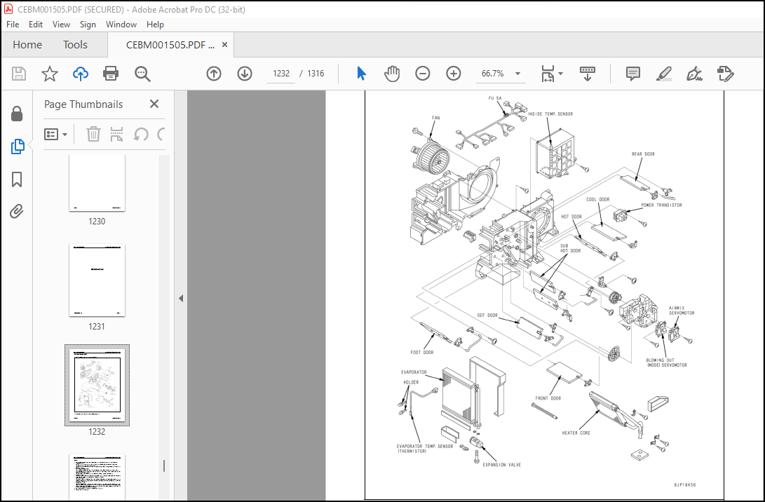
Air Conditioner Unit……………………………………………………………………1232
Functions of Major Components in the Air Conditioner Unit…………………………………..1234
Control Plate………………………………………………………………………….1236
Compressor…………………………………………………………………………….1239
Condenser and Receiver Drier…………………………………………………………….1240
TESTING AND ADJUSTING………………………………………………………………………1241
Caution About Refrigerant……………………………………………………………….1241
Troubleshooting Procedure……………………………………………………………….1242
Block Diagram………………………………………………………………………….1243
Circuit Diagram and Arrangement of Connector Pins………………………………………….1244
Detail of Air Conditioner Unit…………………………………………………………..1246
Part and Connector Locations…………………………………………………………….1248
Testing Air Leakage (Ducts)……………………………………………………………..1252
Testing with Self-diagnosis Function……………………………………………………..1254
Testing Temperature Control……………………………………………………………..1257
Testing Vent (Mode) Changeover…………………………………………………………..1260
Testing Recirc/Fresh Changeover………………………………………………………….1264
Testing Inner Sensor……………………………………………………………………1266
Testing Evaporator Temperature Sensor…………………………………………………….1267
Testing Sunlight Sensor…………………………………………………………………1269
Testing (Dual) Pressure Switch for Refrigerant…………………………………………….1270
Testing Relays…………………………………………………………………………1272
TROUBLESHOOTING……………………………………………………………………………1274
Troubleshooting Chart 1…………………………………………………………………1274
Troubleshooting Chart 2…………………………………………………………………1275
Troubleshooting for Electrical System (E mode)…………………………………………….1278
E-1 Power Supply System (Air Conditioner Does Not Operate)………………………………1279
E-2 Compressor System (Air is Not Cooled)……………………………………………..1283
E-3 Blower Motor System (No Air Comes Out or Air Flow is Abnormal)……………………….1286
E-4 Temperature Cannot be Controlled………………………………………………….1290
E-5 Vent (Mode) Cannot be Changed Over………………………………………………..1293
E-6 Recirc/Fresh Air Cannot be Changed Over……………………………………………1296
Troubleshooting With Gauge Pressure………………………………………………………1299
Connection of Service Tool………………………………………………………………1302
Precautions for connecting air conditioner piping………………………………………….1304
Handling of Compressor Oil………………………………………………………………1305
Control of Compressor Oil……………………………………………………………1305
Adding of Compressor Oil…………………………………………………………….1305
Compressor Replacement………………………………………………………………1306
Applying Compressor Oil for O-ring……………………………………………………1306
Desiccant Replacement Procedure………………………………………………………….1307
90 DIAGRAMS AND DRAWINGS……………………………………………………………………….1309
HYDRAULIC DIAGRAMS AND DRAWINGS……………………………………………………………..1310
PC220LL-8 HYDRAULIC CIRCUIT DIAGRAM………………………………………………………1310
PC200LL-8 HYDRAULIC CIRCUIT DIAGRAM………………………………………………………1311
ELECTRICAL DIAGRAMS AND DRAWINGS…………………………………………………………….1312
ELECTRICAL CIRCUIT DIAGRAM (1/2)…………………………………………………………1312
ELECTRICAL CIRCUIT DIAGRAM (2/2)…………………………………………………………1313
CIRCUIT DIAGRAM RELATED TO SWING HOLDING BRAKE SOLENOID…………………………………….1314
ELECTRICAL CIRCUIT DIAGRAM FOR AIR CONDITIONER…………………………………………….1315
CONNECTOR ARRANGEMENT DIAGRAM……………………………………………………………1316
More products