$45
Komatsu PC210-8, PC210LC-8, PC210NLC-8, PC230NHD-8 PC240NLC-8 Hydraulic Excavator Shop Manual PDF
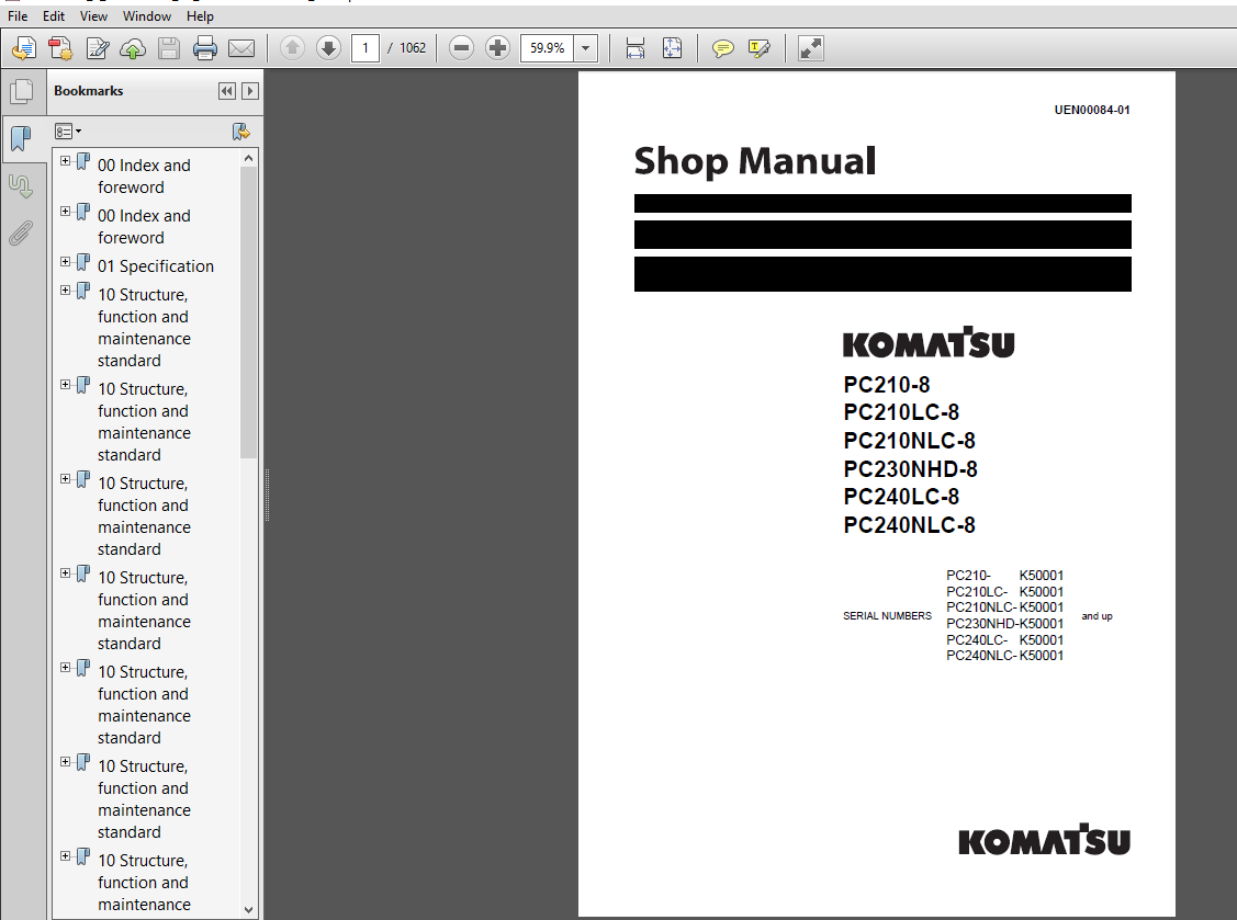
Komatsu PC210-8, PC210LC-8, PC210NLC-8, PC230NHD-8, PC240LC-8, PC240NLC-8 Hydraulic Excavator Shop Manual
FILE DETAILS:
Komatsu PC210-8, PC210LC-8, PC210NLC-8, PC230NHD-8, PC240LC-8, PC240NLC-8 Hydraulic Excavator Shop Manual
File Format : PDF
Language : English
Printable : Yes
Searchable : Yes
Bookmarked : Yes
Product Code : UEN00084-01
Total Pages : 1062
DESCRIPTION:
Komatsu PC210-8, PC210LC-8, PC210NLC-8, PC230NHD-8, PC240LC-8, PC240NLC-8 Hydraulic Excavator Shop Manual
HOW TO READ THE SHOP MANUAL:
1. Composition of shop manual:
This shop manual contains the necessary technical information for services performed in a workshop. For ease of understanding, the manual is divided into the following sections.
00. Index and foreword:
This section explains the shop manuals list, table of contents, safety, and basic information.
01. Specification:
This section explains the specifications of the machine.
10. Structure, function and maintenance standard:
This section explains the structure, function, and maintenance standard values of each component. The structure and function sub-section explains the structure and function of each component. It serves not only to give an understanding of the structure, but also serves as reference material for troubleshooting. The maintenance standard sub-section explains the criteria and remedies for disassembly and service.
20. Standard value table:
This section explains the standard values for new machine and judgement criteria for testing, adjusting, and troubleshooting. This standard value table is used to check the standard values in testing and adjusting and to judge parts in troubleshooting.
30. Testing and adjusting:
This section explains measuring instruments and measuring methods for testing and adjusting, and method of adjusting each part. The standard values and judgement criteria for testing and adjusting are explained in Testing and adjusting.
40. Troubleshooting:
This section explains how to find out failed parts and how to repair them. The troubleshooting is divided by failure modes. The “S mode” of the troubleshooting related to the engine may be also explained in the Chassis volume and Engine volume. In this case, see the Chassis volume.
50. Disassembly and assembly:
This section explains the special tools and procedures for removing, installing, disassembling, and assembling each component, as well as precautions for them. In addition, tightening torque and quantity and weight of coating material, oil, grease, and coolant necessary for the work are also explained.
90. Diagrams and drawings (chassis volume)/Repair and replacement of parts (engine volume):
- Chassis volume
This section gives hydraulic circuit diagrams and electrical circuit diagrams. - Engine volume
This section explains the method of reproducing, repairing, and replacing parts
TABLE OF CONTENTS:
Komatsu PC210-8, PC210LC-8, PC210NLC-8, PC230NHD-8, PC240LC-8, PC240NLC-8 Hydraulic Excavator Shop Manual
00 Index and foreword........................................................................................   3
	Index....................................................................................................   3
		Organization list of the shop manual.................................................................   4
		Table of contents....................................................................................   6
00 Index and foreword........................................................................................  15
	Foreword and general information.........................................................................  15
		Foreword and general information.....................................................................  16
			Safety notice....................................................................................  16
			How to read the shop manual......................................................................  20
			Explanation of terms for maintenance standard....................................................  22
			Handling electric equipment and hydraulic component..............................................  24
			How to read electric wire code...................................................................  32
			Method of disassembling and connecting push-pull type coupler....................................  35
			Standard tightening torque table.................................................................  38
			Conversion table.................................................................................  42
01 Specification.............................................................................................  49
	Specification and technical data.........................................................................  49
		Specification and technical data.....................................................................  50
			Specification dimension drawings.................................................................  50
			Working range diagram............................................................................  51
			Specifications...................................................................................  52
			Weight table.....................................................................................  56
			Table of fuel, coolant and lubricants............................................................  60
10 Structure, function and maintenance standard..............................................................  63
	Engine and cooling system................................................................................  63
		Engine and cooling system............................................................................  64
			Engine related parts.............................................................................  64
			Radiator, oil cooler, aftercooler and fuel cooler................................................  65
10 Structure, function and maintenance standard..............................................................  67
	Power train..............................................................................................  67
		Power train..........................................................................................  68
			Power train......................................................................................  68
			Final drive......................................................................................  70
			Swing machinery..................................................................................  72
			Swing circle.....................................................................................  76
10 Structure, function and maintenance standard..............................................................  79
	Undercarriage and frame..................................................................................  79
		Undercarriage and frame..............................................................................  80
			Track frame and recoil spring....................................................................  80
			Idler............................................................................................  82
			Carrier roller...................................................................................  84
			Track roller.....................................................................................  85
			Track shoe.......................................................................................  86
10 Structure, function and maintenance standard..............................................................  93
	Hydraulic system, Part 1.................................................................................  93
		Hydraulic system, Part 1.............................................................................  94
			Hydraulic equipment layout drawing...............................................................  94
		Hydraulic tank and filter............................................................................  96
			Hydraulic pump...................................................................................  97
			Hydraulic pump...................................................................................  98
			Pilot oil filter................................................................................. 121
10 Structure, function and maintenance standard.............................................................. 123
	Hydraulic system, Part 2................................................................................. 123
		Hydraulic system, Part 2............................................................................. 124
			Control valve.................................................................................... 124
			CLSS............................................................................................. 137
			Functions and operation by valve................................................................. 142
			Hydraulic drift prevention valve................................................................. 168
10 Structure, function and maintenance standard.............................................................. 181
	Hydraulic system, Part 3................................................................................. 181
		Hydraulic system, Part 3............................................................................. 183
			Swing motor...................................................................................... 183
			Center swivel joint.............................................................................. 192
			Travel motor..................................................................................... 195
			PPC valve........................................................................................ 206
			Valve control.................................................................................... 228
			Solenoid valve................................................................................... 230
			PPC Accumulator.................................................................................. 232
			Return oil filter................................................................................ 233
			Attachment circuit selector valve................................................................ 234
			Hydraulic cylinder............................................................................... 236
10 Structure, function and maintenance standard.............................................................. 241
	Work equipment........................................................................................... 241
		Work equipment....................................................................................... 242
			Dimensions of components......................................................................... 242
10 Structure, function and maintenance standard.............................................................. 249
	Cab and its attachments.................................................................................. 249
		Cab and its attachments.............................................................................. 250
			Air conditioner piping........................................................................... 250
10 Structure, function and maintenance standard.............................................................. 253
	Electrical system........................................................................................ 253
		Electrical system.................................................................................... 254
			Engine control................................................................................... 254
			Electrical control system........................................................................ 262
			Monitor system................................................................................... 282
			Sensor........................................................................................... 309
			KOMTRAX terminal system.......................................................................... 312
20 Standard value table...................................................................................... 315
	Standard service value table............................................................................. 315
		Standard service value table......................................................................... 316
			Standard value table for engine related parts.................................................... 316
			Standard value table for chassis related parts................................................... 318
30 Testing and adjusting..................................................................................... 337
	Testing and adjusting, Part 1............................................................................ 337
		Testing and adjusting, Part 1........................................................................ 339
			Tools for testing, adjusting, and troubleshooting................................................ 339
			Measuring engine speed........................................................................... 342
			Measuring intake air pressure (boost pressure)................................................... 343
			Checking exhaust gas color....................................................................... 344
			Adjusting valve clearance........................................................................ 345
			Measuring compression pressure................................................................... 347
			Measuring blow-by pressure....................................................................... 349
			Measuring engine oil pressure.................................................................... 350
			Handling fuel system parts....................................................................... 351
			Releasing residual pressure from fuel system..................................................... 351
			Measuring fuel pressure.......................................................................... 352
			Measuring fuel return rate and leakage........................................................... 354
			Bleeding air from fuel circuit................................................................... 356
			Checking fuel circuit for leakage................................................................ 358
			Checking and adjusting air conditioner compressor belt tension................................... 359
			Measuring swing circle bearing clearance......................................................... 360
			Checking and adjusting track shoe tension........................................................ 361
			Measuring and adjusting oil pressure in work equipment, swing, and travel circuits............... 363
			Measuring control circuit basic pressure......................................................... 367
			Measuring and adjusting oil pressure in pump PC control circuit.................................. 368
			Measuring and adjusting oil pressure in pump LS control circuit.................................. 372
			Measuring solenoid valve output pressure......................................................... 378
			Measuring PPC valve output pressure.............................................................. 381
			Adjusting play of work equipment and swing PPC valves............................................ 383
			Checking parts which cause hydraulic drift of work equipment..................................... 384
			Releasing residual pressure from hydraulic circuit............................................... 386
			Measuring oil leakage............................................................................ 387
			Bleeding air from each part...................................................................... 390
			Checking cab tipping stopper..................................................................... 393
			Adjusting mirrors................................................................................ 394
30 Testing and adjusting..................................................................................... 397
	Testing and adjusting, Part 2............................................................................ 397
		Testing and adjusting, Part 2........................................................................ 398
			Special functions of machine monitor............................................................. 398
30 Testing and adjusting..................................................................................... 455
	Testing and adjusting, Part 3............................................................................ 455
		Testing and adjusting, Part 3........................................................................ 456
			Handling high-voltage circuit of engine controller............................................... 456
			Preparation work for troubleshooting of electrical system........................................ 457
			Procedure for testing diodes..................................................................... 461
			Pm Clinic service................................................................................ 463
			Warning.......................................................................................... 465
			Pm Clinic service................................................................................ 469
40 Troubleshooting........................................................................................... 477
	General information on troubleshooting................................................................... 477
		General information on troubleshooting............................................................... 478
			Points to remember when troubleshooting.......................................................... 478
			Sequence of events in troubleshooting............................................................ 479
			Check before troubleshooting..................................................................... 480
			Classification and procedures for troubleshooting................................................ 481
			How to read electric wire code................................................................... 485
			Connection table for connector pin numbers....................................................... 488
			T-boxes and T-adapters table..................................................................... 511
40 Troubleshooting........................................................................................... 515
	Troubleshooting by failure code (Display of code), Part 1................................................ 515
		Troubleshooting by failure code (Display of code), Part 1............................................ 517
			Failure codes table.............................................................................. 517
			Before carrying out troubleshooting when failure code is displayed............................... 522
			Information in troubleshooting table............................................................. 526
			Failure code [989L00] Engine Controller Lock Caution 1........................................... 528
			Failure code [989M00] Engine Controller Lock Caution 2........................................... 528
			Failure code [989N00] Engine Controller Lock Caution 3........................................... 529
			Failure code [AA10NX] Air Cleaner Clogging....................................................... 529
			Failure code [AB00KE] Charge Voltage Low......................................................... 530
			Failure code [B@BAZG] Eng Oil Press. Low......................................................... 532
			Failure code [B@BAZK] Eng Oil Level Low.......................................................... 532
			Failure code [B@BCNS] Eng Water Overheat......................................................... 533
			Failure code [B@BCZK] Eng Water Level Low........................................................ 533
			Failure code [B@HANS] Hydr Oil Overheat.......................................................... 534
			Failure code [CA111] EMC Critical Internal Failure............................................... 534
			Failure code [CA115] Eng Ne and Bkup Speed Sens Error............................................ 535
			Failure code [CA122] Chg Air Press Sensor High Error............................................. 536
			Failure code [CA123] Chg Air Press Sensor Low Error.............................................. 538
			Failure code [CA131] Throttle Sensor High Error.................................................. 540
			Failure code [CA132] Throttle Sensor Low Error................................................... 542
			Failure code [CA144] Coolant Temp Sens High Error................................................ 544
			Failure code [CA145] Coolant Temp Sens Low Error................................................. 546
			Failure code [CA153] Chg Air Temp Sensor High Error.............................................. 548
			Failure code [CA154] Chg Air Temp Sensor Low Error............................................... 550
			Failure code [CA155] Chg Air Temp High Speed Derate.............................................. 552
			Failure code [CA187] Sens Supply 2 Volt Low Error................................................ 554
			Failure code [CA221] Ambient Press Sens High Error............................................... 556
			Failure code [CA222] Ambient Press Sens Low Error................................................ 558
			Failure code [CA227] Sens Supply 2 Volt High Error............................................... 560
			Failure code [CA234] Eng Overspeed............................................................... 561
			Failure code [CA238] Ne Speed Sens Supply Volt Error............................................. 562
			Failure code [CA271] IMV/PCV1 Short Error........................................................ 563
			Failure code [CA272] IMV/PCV1 Open Error......................................................... 564
			Failure code [CA322] Inj #1 (L#1) Open/Short Error............................................... 566
			Failure code [CA323] Inj #5 (L#5) Open/Short Error............................................... 568
			Failure code [CA324] Inj #3 (L#3) Open/Short Error............................................... 570
			Failure code [CA325] Inj #6 (L#6) Open/Short Error............................................... 572
			Failure code [CA331] Inj #2 (L#2) Open/Short Error............................................... 574
			Failure code [CA332] Inj #4 (L#4) Open/Short Error............................................... 576
40 Troubleshooting........................................................................................... 579
	Troubleshooting by failure code (Display of code), Part 2................................................ 579
		Troubleshooting by failure code (Display of code), Part 2............................................ 581
			Failure code [CA342] Calibration Code Incompatibility............................................ 581
			Failure code [CA351] Injectors Drive Circuit Error............................................... 582
			Failure code [CA352] Sens Supply 1 Volt Low Error................................................ 584
			Failure code [CA386] Sens Supply 1 Volt High Error............................................... 586
			Failure code [CA428] Water in Fuel Sensor High Error............................................. 588
			Failure code [CA429] Water in Fuel Sensor Low Error.............................................. 590
			Failure code [CA435] Eng Oil Press Sw Error...................................................... 592
			Failure code [CA441] Battery Voltage Low Error................................................... 593
			Failure code [CA442] Battery Voltage High Error.................................................. 596
			Failure code [CA449] Rail Press Very High Error.................................................. 598
			Failure code [CA451] Rail Press Sensor High Error................................................ 600
			Failure code [CA452] Rail Press Sensor Low Error................................................. 602
			Failure code [CA488] Chg Air Temp High Torque Derate............................................. 604
			Failure code [CA553] Rail Press High Error....................................................... 604
			Failure code [CA559] Rail Press Low Error........................................................ 605
			Failure code [CA689] Eng Ne Speed Sensor Error................................................... 606
			Failure code [CA731] Eng Bkup Speed Sens Phase Error............................................. 608
			Failure code [CA757] All Continuous Data Lost Error.............................................. 610
			Failure code [CA778] Eng Bkup Speed Sensor Error................................................. 612
			Failure code [CA1633] KOMNET Datalink Timeout Error.............................................. 614
			Failure code [CA2185] Throt Sens Sup Volt High Error............................................. 616
			Failure code [CA2186] Throt Sens Sup Volt Low Error.............................................. 617
			Failure code [CA2249] Rail Press Very Low Error.................................................. 618
			Failure code [CA2311] IMV Solenoid Error......................................................... 620
			Failure code [CA2555] Grid Htr Relay Volt High Error............................................. 622
			Failure code [CA2556] Grid Htr Relay Volt Low Error.............................................. 624
			Failure code [D19JKZ] Personal Code Relay Abnormality............................................ 626
			Failure code [D862KA] GPS Antenna Discon......................................................... 628
			Failure code [DA25KP] 5V Sensor 1 Power Abnormality.............................................. 629
			Failure code [DA29KQ] Model Selection Abnormality................................................ 636
40 Troubleshooting........................................................................................... 641
	Troubleshooting by failure code (Display of code), Part 3................................................ 641
		Troubleshooting by failure code (Display of code), Part 3............................................ 644
			Failure code [DA2RMC] CAN Discon (Pump Con Detected)............................................. 644
			Failure code [DAFGMC] GPS Module Error........................................................... 646
			Failure code [DAFRMC] CAN Discon (Monitor Detected).............................................. 648
			Failure code [DGH2KB] Hydr Oil Sensor Short...................................................... 650
			Failure code [DHPAMA] F Pump Press Sensor Abnormality............................................ 652
			Failure code [DHPBMA] R Pump Press Sensor Abnormality............................................ 654
			Failure code [DHS3MA] Arm Curl PPC Press Sensor Abnormality...................................... 656
			Failure code [DHS4MA] Bucket Curl PPC Press Sensor Abnormality................................... 658
			Failure code [DHS8MA] Boom Raise PPC Press Sensor Abnormality.................................... 660
			Failure code [DHSAMA] Swing RH PPC Press Sensor Abnormality...................................... 662
			Failure code [DHSBMA] Swing LH PPC Press Sensor Abnormality...................................... 664
			Failure code [DHSDMA] Bucket Dump PPC Press Sensor Abnormality................................... 666
			Failure code [DHX1MA] Overload Sensor Abnormality (Analog)....................................... 668
			Failure code [DW43KA] Travel Speed Sol Discon.................................................... 670
			Failure code [DW43KB] Travel Speed Sol Short..................................................... 672
			Failure code [DW45KA] Swing Brake Sol Discon..................................................... 674
			Failure code [DW45KB] Swing Brake Sol Short...................................................... 676
			Failure code [DW91KA] Travel Junction Sol Discon................................................. 678
			Failure code [DW91KB] Travel Junction Sol Short.................................................. 680
			Failure code [DWA2KA] Service Sol Discon......................................................... 682
			Failure code [DWA2KB] Service Sol Short.......................................................... 683
			Failure code [DWK0KA] 2-stage Relief Sol Discon.................................................. 684
			Failure code [DWK0KB] 2-stage Relief Sol Short................................................... 686
40 Troubleshooting........................................................................................... 689
	Troubleshooting by failure code (Display of code), Part 4................................................ 689
		Troubleshooting by failure code (Display of code), Part 4............................................ 692
			Failure code [DXA8KA] PC-EPC (F) Sol Discon...................................................... 692
			Failure code [DXA8KB] PC-EPC (F) Sol Short....................................................... 694
			Failure code [DXA9KA] PC-EPC (R) Sol Discon...................................................... 696
			Failure code [DXA9KB] PC-EPC (R) Sol Short....................................................... 698
			Failure code [DXE0KA] LS-EPC Sol Discon.......................................................... 700
			Failure code [DXE0KB] LS-EPC Sol Short........................................................... 702
			Failure code [DXE4KA] Service Current EPC Discon................................................. 704
			Failure code [DXE4KB] Service Current EPC Short.................................................. 706
			Failure code [DXE5KA] Merge-divider Main Sol Discon.............................................. 708
			Failure code [DXE5KB] Merge-divider Main Sol Short............................................... 710
			Failure code [DXE6KA] Merge-divider LS Sol Discon................................................ 712
			Failure code [DXE6KB] Merge-divider LS Sol Short................................................. 714
			Failure code [DY20KA] Wiper Working Abnormality.................................................. 716
			Failure code [DY20MA] Wiper Parking Abnormality.................................................. 718
			Failure code [DY2CKA] Washer Drive Discon........................................................ 720
			Failure code [DY2CKB] Washer Drive Short......................................................... 722
			Failure code [DY2DKB] Wiper Drive (For) Short.................................................... 724
			Failure code [DY2EKB] Wiper Drive (Rev) Short.................................................... 726
40 Troubleshooting........................................................................................... 729
	Troubleshooting of electrical system (E-mode)............................................................ 729
		Troubleshooting of electrical system (E-mode)........................................................ 731
			Before carrying out troubleshooting of electrical system......................................... 731
			Information in troubleshooting table............................................................. 733
			E-1 When starting switch turned ON, machine monitor displays nothing............................. 734
			E-2 When starting switch turned ON (before starting engine), basic check item lights up.......... 736
			E-3 Engine does not start (Engine does not turn)................................................. 739
			E-4 Preheater does not operate................................................................... 742
			E-5 Automatic warm-up system does not operate (in cold season)................................... 744
			E-6 All work equipment, swing, and travel mechanism do not move or cannot be locked.............. 746
			E-7 Precaution lights up while engine is running................................................. 748
			E-8 Emergency stop item lights up while engine is running........................................ 753
			E-9 Engine coolant temperature gauge does not indicate normally.................................. 754
			E-10 Hydraulic oil temperature gauge does not indicate normally.................................. 755
			E-11 Fuel level gauge does not indicate normally................................................. 757
			E-12 Contents of display by machine monitor are different from applicable machine................ 759
			E-13 Machine monitor does not display some items................................................. 759
			E-14 Function switch does not work............................................................... 759
			E-15 Auto-decelerator does not operate normally.................................................. 760
			E-16 Working mode does not change................................................................ 761
			E-17 Travel speed does not change................................................................ 762
			E-18 Alarm buzzer cannot be stopped.............................................................. 763
			E-19 Windshield wiper and window washer do not operate........................................... 764
			E-20 Power maximizing function does not operate normally......................................... 766
			E-21 Swing holding brake does not operate normally............................................... 768
			E-22 Travel alarm does not sound or does not stop sounding....................................... 770
			E-23 Air conditioner does not operate normally (including air conditioner abnormality record).... 772
			E-24 When starting switch is turned OFF, service meter is not displayed.......................... 784
			E-25 Machine monitor cannot be set in service mode............................................... 784
			E-26 Monitoring function does not display lever control signal normally.......................... 785
			E-27 KOMTRAX system does not operate normally.................................................... 794
40 Troubleshooting........................................................................................... 797
	Troubleshooting of hydraulic and mechanical system (H-mode).............................................. 797
		Troubleshooting of hydraulic and mechanical system (H-mode).......................................... 800
			System diagram of hydraulic and mechanical system................................................ 800
			Information in troubleshooting table............................................................. 802
			H-1 Speed or power of whole work equipment, swing, and travel is low............................. 803
			H-2 Engine speed lowers extremely or engine stalls............................................... 805
			H-3 Work equipment, swing, and travel systems do not work........................................ 806
			H-4 Abnormal sound comes out from around hydraulic pump.......................................... 806
			H-5 Auto-decelerator does not operate............................................................ 807
			H-6 Fine control performance or response is low.................................................. 807
			H-7 Speed or power of boom is low................................................................ 808
			H-8 Speed or power of arm is low................................................................. 809
			H-9 Speed or power of bucket is low.............................................................. 810
			H-10 Work equipment does not move singly......................................................... 810
			H-11 Hydraulic drift of work equipment is large.................................................. 811
			H-12 Time lag of work equipment is large......................................................... 813
			H-13 When part of work equipment is relieved singly, other parts of work equipment move.......... 813
			H-14 Power maximizing function does not work..................................................... 814
			H-15 In compound operation of work equipment, speed of part loaded more is low................... 814
			H-16 When machine swings and raises boom simultaneously, boom rising speed is low................ 815
			H-17 When machine swings and travels simultaneously, travel speed lowers largely................. 815
			H-18 Machine deviates during travel.............................................................. 816
			H-19 Travel speed is low......................................................................... 817
			H-20 Machine is not steered well or steering power is low........................................ 818
			H-21 Travel speed does not change or travel speed is low/high.................................... 819
			H-22 Travel system does not move (only one side)................................................. 820
			H-23 Upper structure does not swing.............................................................. 821
			H-24 Swing acceleration or swing speed is low.................................................... 823
			H-25 Upper structure overruns remarkably when it stops swinging.................................. 824
			H-26 Large shock is made when upper structure stops swinging..................................... 825
			H-27 Large sound is made when upper structure stops swinging..................................... 825
			H-28 Hydraulic drift of swing is large........................................................... 826
			H-29 Attachment circuit is not changed........................................................... 827
			H-30 Oil flow in attachment circuit cannot be controlled......................................... 827
40 Troubleshooting........................................................................................... 829
	Troubleshooting of engine (S-mode)....................................................................... 829
		Troubleshooting of engine (S-mode)................................................................... 831
			Method of using troubleshooting chart............................................................ 831
			S-1 Starting performance is poor................................................................. 834
			S-2 Engine does not start........................................................................ 835
			S-3 Engine does not pick up smoothly............................................................. 838
			S-4 Engine stops during operations............................................................... 839
			S-5 Engine does not rotate smoothly.............................................................. 840
			S-6 Engine lack output (or lacks power).......................................................... 841
			S-7 Exhaust smoke is black (incomplete combustion)............................................... 842
			S-8 Oil consumption is excessive (or exhaust smoke is blue)...................................... 843
			S-9 Oil becomes contaminated quickly............................................................. 844
			S-10 Fuel consumption is excessive............................................................... 845
			S-11 Oil is in coolant (or coolant spurts back or coolant level goes down)....................... 846
			S-12 Oil pressure drops.......................................................................... 847
			S-13 Oil level rises (Entry of coolant/fuel)..................................................... 848
			S-14 Coolant temperature becomes too high (overheating).......................................... 849
			S-15 Abnormal noise is made...................................................................... 850
			S-16 Vibration is excessive...................................................................... 851
50 Disassembly and assembly.................................................................................. 853
	Disassembly and assembly related information............................................................. 853
		Disassembly and assembly related information......................................................... 854
			How to read this manual.......................................................................... 854
			List of adhesives................................................................................ 856
			Special tool list................................................................................ 859
			Sketches of special tools........................................................................ 864
50 Disassembly and assembly.................................................................................. 869
	Engine cooling related................................................................................... 869
		Engine cooling related............................................................................... 870
			Removal and installation of fuel supply pump assembly............................................ 870
			Removal and installation of fuel injector assembly............................................... 872
			Removal and installation of engine front seal.................................................... 879
			Removal and installation of engine rear seal..................................................... 882
			Removal and installation of cylinder head assembly............................................... 885
			Removal and installation of radiator assembly.................................................... 897
			Removal and installation of assembly hydraulic oil cooler assembly............................... 900
			Removal and installation of aftercooler assembly................................................. 902
			Removal and installation of fuel cooler assembly................................................. 904
			Removal and installation of engine and hydraulic pump assemblies................................. 905
50 Disassembly and assembly.................................................................................. 917
	Power train.............................................................................................. 917
		Power train.......................................................................................... 918
			Removal and installation of final drive assembly................................................. 918
			Disassembly and assembly of final drive assembly................................................. 920
			Removal and installation of swing motor and swing machinery assembly............................. 936
			Disassembly and assembly of swing motor and swing machinery assembly............................. 938
			Removal and installation of swing circle assembly................................................ 948
50 Disassembly and assembly.................................................................................. 951
	Under carriage and frame................................................................................. 951
		Under carriage and frame............................................................................. 952
			Disassembly and assembly of carrier roller....................................................... 952
			Disassembly and assembly of track roller assembly................................................ 955
			Disassembly and assembly of idler assembly....................................................... 957
			Disassembly and assembly of recoil spring........................................................ 960
			Removal and installation of sprocket............................................................. 962
			Expansion and installation of track shoe assembly................................................ 963
			Removal and installation of revolving frame assembly............................................. 965
			Removal and installation of counterweight assembly............................................... 967
50 Disassembly and assembly.................................................................................. 969
	Hydraulic system......................................................................................... 969
		Hydraulic system..................................................................................... 970
			Removal and installation of center swivel joint assembly......................................... 970
			Disassembly and assembly of center swivel joint assembly......................................... 972
			Removal and installation of hydraulic tank assembly.............................................. 973
			Removal and installation of control valve assembly............................................... 976
			Disassembly and assembly of control valve assembly............................................... 981
			Removal and installation of hydraulic pump assembly.............................................. 985
			Removal and installation of oil seal in hydraulic pump input shaft............................... 990
			Disassembly and assembly of work equipment PPC valve assembly.................................... 991
			Disassembly and assembly of travel PPC valve assembly............................................ 992
			Disassembly and assembly of hydraulic cylinder assembly.......................................... 993
50 Disassembly and assembly..................................................................................1001
	Work equipment...........................................................................................1001
		Work equipment.......................................................................................1002
			Removal and installation of the work equipment assembly..........................................1002
50 Disassembly and assembly..................................................................................1007
	Cab related..............................................................................................1007
		Cab related..........................................................................................1008
			Removal and installation of operator's cab assembly..............................................1008
			Removal and installation of operator cab glass (stuck glass).....................................1011
			Removal and installation of front window assembly................................................1021
			Removal and installation of floor frame assembly.................................................1028
50 Disassembly and assembly..................................................................................1033
	Electric components......................................................................................1033
		Electric components..................................................................................1034
			Removal and installation of air conditioner unit assembly........................................1034
			Removal and installation of KOMTRAX communication modem assembly.................................1037
			Removal and installation of monitor assembly.....................................................1038
			Removal and installation of pump controller assembly.............................................1040
			Removal and installation of engine controller assembly...........................................1041
90 Diagrams and drawings.....................................................................................1043
	Hydraulic diagrams and drawings..........................................................................1043
		Hydraulic diagrams and drawings......................................................................1045
			Hydraulic circuit diagram........................................................................1045
90 Diagrams and drawings.....................................................................................1049
	Electrical diagrams and drawings.........................................................................1049
		Electrical diagrams and drawings.....................................................................1051
			Electrical circuit diagram (1/5).................................................................1051
			Electrical circuit diagram (2/5).................................................................1053
			Electrical circuit diagram (3/5).................................................................1055
			Electrical circuit diagram (4/5).................................................................1057
			Electrical circuit diagram (5/5).................................................................1059
IMAGES PREVIEW OF THE MANUAL:
More products