$43
Komatsu PC290LC-8 Hydraulic Excavator Shop Manual SEN06728-01 – PDF DOWNLOAD
Komatsu PC290LC-8 Hydraulic Excavator Shop Manual SEN06728-01 – PDF DOWNLOAD
FILE DETAILS:
Komatsu PC290LC-8 Hydraulic Excavator Shop Manual SEN06728-01 – PDF DOWNLOAD
Language : English
Pages : 990
Downloadable : Yes
File Type : PDF
Size: 77.9 MB
DESCRIPTION:
Komatsu PC290LC-8 Hydraulic Excavator Shop Manual SEN06728-01 – PDF DOWNLOAD
SERIAL NUMBERS 30742 and up
GENERAL PRECAUTIONS:
Mistakes in operation are extremely dangerous. Read the Operation and Maintenance Manual carefully BEFORE operating the machine.1. Before carrying out any greasing or repairs, read all the precautions given on the decals which are fixed to the machine.2. When carrying out any operation, always wear safety shoes and helmet. Do not wear loose work clothes, or clothes with buttons missing.• Always wear safety glasses when hitting parts with a hammer.• Always wear safety glasses when grinding parts with a grinder, etc.3. If welding repairs are needed, always have a trained, experienced welder carry out the work. When carrying out welding work, always wear welding gloves, apron, hand shield, cap and other clothes suited for welding work.4. When carrying out any operation with two or more workers, always agree on the operating procedure before starting. Always inform your fellow workers before starting any step of the operation. Before starting work, hang UNDER REPAIR signs on the controls in the operator’s compartment.5. Keep all tools in good condition and learn the correct way to use them.
6. Decide a place in the repair workshop to keep tools and removed parts. Always keep the tools and parts in their correct places. Always keep the work area clean and make sure that there is no dirt or oil on the floor. Smoke only in the areas provided for smoking. Never smoke while working.
PREPARATIONS FOR WORK:
- 7. Before adding oil or making any repairs, park the machine on hard, level ground, and block the wheels or tracks to prevent the machine from moving.
- 8. Before starting work, lower blade, ripper, bucket or any other work equipment to the ground. If this is not possible, insert the safety pin or use blocks to prevent the work equipment from falling. In addition, be sure to lock all the control levers and hang warning signs on them.
- 9. When disassembling or assembling, support the machine with blocks, jacks or stands before starting work.
- 10.Remove all mud and oil from the steps or other places used to get on and off the machine. Always use the handrails, ladders or steps when getting on or off the machine. Never jump on or off the machine. If it is impossible to use the handrails, ladders or steps, use a stand to provide safe footing.
FOREWORD
GENERAL
This shop manual has been prepared as an aid to improve the quality of repairs by giving the serviceman an
accurate understanding of the product and by showing him the correct way to perform repairs and make judgements.
Make sure you understand the contents of this manual and use it to full effect at every opportunity.
This shop manual mainly contains the necessary technical information for operations performed in a service
workshop. For ease of understanding, the manual is divided into the following chapters; these chapters are further
divided into the each main group of components.
STRUCTURE AND FUNCTION
This section explains the structure and function of each component. It serves not only to give an understanding
of the structure, but also serves as reference material for troubleshooting.
In addition, this section may contain hydraulic circuit diagrams, electric circuit diagrams, and maintenance
standards.
TESTING AND ADJUSTING
This section explains checks to be made before and after performing repairs, as well as adjustments to
be made at completion of the checks and repairs.
Troubleshooting charts correlating “Problems” with “Causes” are also included in this section.
DISASSEMBLY AND ASSEMBLY
This section explains the procedures for removing, installing, disassembling and assembling each component,
as well as precautions for them.
MAINTENANCE STANDARD
This section gives the judgment standards for inspection of disassembled parts.
The contents of this section may be described in STRUCTURE AND FUNCTION.
OTHERS
This section mainly gives hydraulic circuit diagrams and electric circuit diagrams.
In addition, this section may give the specifications of attachments and options together.
TABLE OF CONTENTS:
Komatsu PC290LC-8 Hydraulic Excavator Shop Manual SEN06728-01 – PDF DOWNLOAD
Cover 1
00 Index and foreword 3
Index 4
Foreword and general information 11
Safety notice 11
How to read the shop manual 16
Explanation of terms for maintenance standard 18
Handling of electric equipment and hydraulic component 20
Handling of connectors newly used for engines 29
How to read electric wire code 32
Precautions when carrying out operation 35
Method of disassembling and connecting push-pull type coupler 38
Standard tightening torque table 41
Conversion table 45
01 Specification 51
Contents 52
Specification and technical data 53
Specification dimension drawings 53
Working range diagram 54
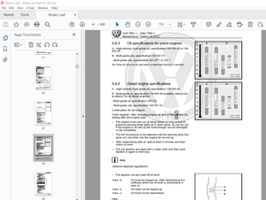
Specifications 55
Weight table 57
Table of fuel, coolant and lubricants 59
10 Structure, function and maintenance standard 61
Contents 62
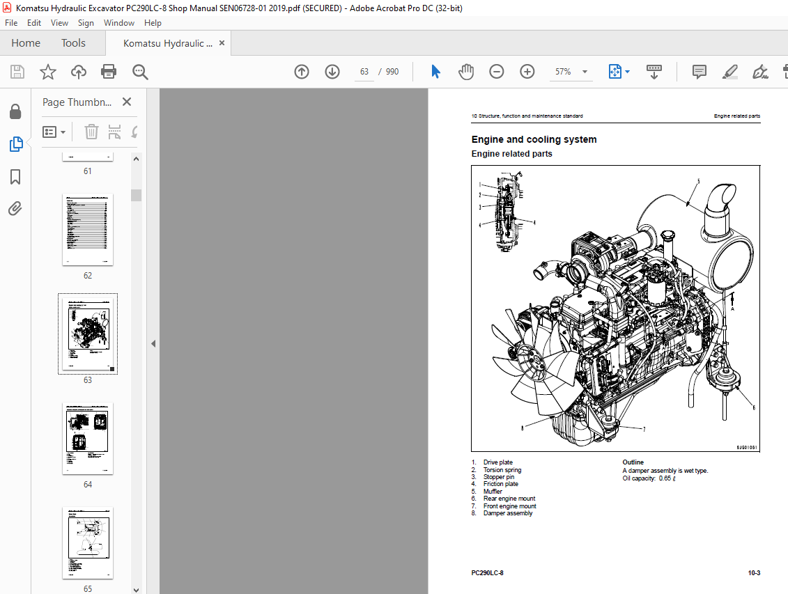
Engine and cooling system 63
Engine related parts 63
Radiator, oil cooler, aftercooler and fuel cooler 64
Power train 65
Power train 65
Final drive 66
Swing machinery 68
Swing circle 70
Undercarriage and frame 71
Track frame and recoil spring 71
Idler 73
Carrier roller 75
Track roller 76
Track shoe 77
Hydraulic system 80
Hydraulic equipment layout drawing 80
Hydraulic tank and filter 82
Hydraulic pump 84
Pilot oil filter 106
Control valve 107
CLSS 118
Functions and operation by valve 122
Swing motor 160
Center swivel joint 168
Travel motor 170
PPC valve 182
Valve control 202
Solenoid valve 204
PPC accumulator 206
Return oil filter 207
Attachment circuit selector valve 208
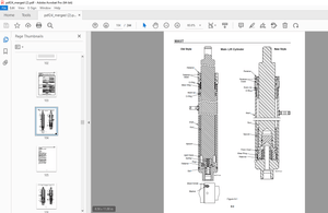
Hydraulic cylinder 210
Work equipment 212
Dimensions of components 212
Cab and its attachments 218
Air conditioner piping 218
Electrical system 219
Engine control 219
Electrical control system 228
Monitor system 251
Sensor 277
KOMTRAX system 280
Contents 284
20 Standard value table 283
Contents 284
Standard service value table 285
Standard value table for engine related parts 285
Standard value table for chassis related parts 286
30 Testing and adjusting 297
Contents 298
Related information on testing and adjusting 299
Tools for testing, adjusting, and troubleshooting 299
Sketch of special tool 303
Engine and cooling system 304
Testing engine speed 304
Testing intake air pressure (boost pressure) 305
Checking exhaust gas color 306
Adjusting valve clearance 307
Testing compression pressure 309
Testing blow-by pressure 311
Testing engine oil pressure 312
Handling fuel system parts 313
Releasing residual pressure from fuel system 313
Testing fuel pressure 314
Testing fuel delivery, return and leak amount 317
Bleeding air from fuel circuit 320
Checking fuel circuit for leakage 321
Checking and adjusting air conditioner compressor belt tension 322
Replacing fan belt 323
Power train 324
Testing swing circle bearing clearance 324
Undercarriage and frame 325
Checking and adjusting track shoe tension 325
Hydraulic system 327
Testing and adjusting oil pressure in work equipment, swing, and travel circuits 327
Testing control circuit basic pressure 330
Testing and adjusting oil pressure in pump PC control circuit 331
Testing and adjusting oil pressure in pump LS control circuit 334
Testing solenoid valve output pressure 339
Testing PPC valve output pressure 342
Adjusting play of work equipment and swing PPC valves 344
Checking parts which cause hydraulic drift of work equipment 345
Releasing residual pressure from hydraulic circuit 347
Testing oil leakage 348
Bleeding air from each part 351
Cab and its attachments 353
Checking cab tipping stopper 353
Installation and adjustment of mirrors 354
Electrical system 357
Special functions of machine monitor 357
Handling voltage circuit of engine controller 412
Preparation work for troubleshooting of electrical system 413
Procedure for testing diodes 418
Pm Clinic 419
Pm Clinic service 419
Contents 426
40 Troubleshooting 425
Contents 426
General Information on troubleshooting 430
Points to remember when troubleshooting 430
Sequence of events in troubleshooting 431
Check before troubleshooting 432
Classification and procedures for troubleshooting 433
How to read electric wire code 437
Information in troubleshooting table 440
Connection table for connector pin numbers 442
T- branch box and T- branch adapter table 478
Failure codes table 481
Fuse locations 486
Troubleshooting by failure code (Display of code) 490
Failure code [989L00] Engine Controller Lock Caution 1 490
Failure code [989M00] Engine Controller Lock Caution 2 490
Failure code [989N00] Engine Controller Lock Caution 3 491
Failure code [AA10NX] Air Cleaner Clogging 491
Failure code [AB00KE] Charge Voltage Low 492
Failure code [B@BAZG] Eng Oil Press Low 494
Failure code [B@BAZK] Eng Oil Level Low 494
Failure code [B@BCNS] Eng Water Overheat 495
Failure code [B@BCZK] Eng Water Level Low 495
Failure code [B@HANS] Hydr Oil Overheat 496
Failure code [CA111] EMC Critical Internal Failure 496
Failure code [CA115] Eng Ne and Bkup Speed Sens Error 497
Failure code [CA122] Chg Air Press Sensor High Error 498
Failure code [CA123] Chg Air Press Sensor Low Error 500
Failure code [CA131] Throttle Sensor High Error 502
Failure code [CA132] Throttle Sensor Low Error 504
Failure code [CA144] Coolant Temp Sens High Error 506
Failure code [CA145] Coolant Temp Sens Low Error 508
Failure code [CA153] Chg Air Temp Sensor High Error 510
Failure code [CA154] Chg Air Temp Sensor Low Error 512
Failure code [CA155] Chg Air Temp High Speed Derate 514
Failure code [CA187] Sens Supply 2 Volt Low Error 515
Failure code [CA221] Ambient Press Sens High Error 517
Failure code [CA222] Ambient Press Sens Low Error 519
Failure code [CA227] Sens Supply 2 Volt High Error 521
Failure code [CA234] Eng Overspeed 522
Failure code [CA238] Ne Speed Sens Supply Volt Error 523
Failure code [CA271] IMV/PCV1 Short Error 524
Failure code [CA272] IMV/PCV1 Open Error 525
Failure code [CA322] Inj #1 Open/Short Error 527
Failure code [CA323] Inj #5 Open/Short Error 529
Failure code [CA324] Inj #3 Open/Short Error 531
Failure code [CA325] Inj #6 Open/Short Error 533
Failure code [CA331] Inj #2 Open/Short Error 535
Failure code [CA332] Inj #4 Open/Short Error 537
Failure code [CA342] Calibration Code Incompatibility 539
Failure code [CA351] Injectors Drive Circuit Error 540
Failure code [CA352] Sens Supply 1 Volt Low Error 542
Failure code [CA386] Sens Supply 1 Volt High Error 544
Failure code [CA428] Water in Fuel Sensor High Error 545
Failure code [CA429] Water in Fuel Sensor Low Error 547
Failure code [CA435] Eng Oil Press Sw Error 549
Failure code [CA441] Battery Voltage Low Error 550
Failure code [CA442] Battery Voltage High Error 553
Failure code [CA449] Rail Press Very High Error 555
Failure code [CA451] Rail Press Sensor High Error 556
Failure code [CA452] Rail Press Sensor Low Error 558
Failure code [CA488] Chg Air Temp High Torque Derate 560
Failure code [CA553] Rail Press High Error 561
Failure code [CA559] Rail Press Low Error 562
Failure code [CA689] Eng Ne Speed Sensor Error 564
Failure code [CA731] Eng Bkup Speed Sens Phase Error 566
Failure code [CA757] All Continuous Data Lost Error 567
Failure code [CA778] Eng Bkup Speed Sensor Error 569
Failure code [CA1633] KOMNET Datalink Timeout Error 571
Failure code [CA2185] Throt Sens Sup Volt High Error 572
Failure code [CA2186] Throt Sens Sup Volt Low Error 573
Failure code [CA2249] Rail Press Very Low Error 574
Failure code [CA2311] IMV Solenoid Error 575
Failure code [CA2555] Grid Htr Relay Volt High Error 577
Failure code [CA2556] Grid Htr Relay Volt Low Error 579
Failure code [D19JKZ] Personal Code Relay Abnormality 581
Failure code [D862KA] GPS Antenna Discon 583
Failure code [DA22KK] Pump Solenoid Power Low Error 584
Failure code [DA25KP] 5V Sensor 1 Power Abnormality 586
Failure code [DA29KQ] Model Selection Abnormality 592
Failure code [DA2RMC] CAN Discon (Pump Con Detected) 594
Failure code [DAF8KB] Short circuit in camera power supply 601
Failure code [DAFGMC] GPS Module Error 603
Failure code [DAFRMC] CAN Discon (Monitor Detected) 604
Failure code [DGH2KB] Hydr Oil Sensor Short 609
Failure code [DHPAMA] F Pump Press Sensor Abnormality 610
Failure code [DHPBMA] R Pump Press Sensor Abnormality 612
Failure code [DHS3MA] Arm Curl PPC Press Sensor Abnormality 614
Failure code [DHS4MA] Bucket Curl PPC Press Sensor Abnormality 616
Failure code [DHS8MA] Boom Raise PPC Press Sensor Abnormality 618
Failure code [DHSAMA] Swing RH PPC Press Sensor Abnormality 620
Failure code [DHSBMA] Swing LH PPC Press Sensor Abnormality 622
Failure code [DHSDMA] Bucket Dump PPC Press Sensor Abnormality 624
Failure code [DHX1MA] Overload Sensor Abnormality (Analog) 626
Failure code [DW43KA] Travel Speed Sol Discon 629
Failure code [DW43KB] Travel Speed Sol Short 631
Failure code [DW45KA] Swing Brake Sol Discon 633
Failure code [DW45KB] Swing Brake Sol Short 635
Failure code [DW91KA] Travel Junction Sol Discon 637
Failure code [DW91KB] Travel Junction Sol Short 639
Failure code [DWA2KA] Service Sol Discon 641
Failure code [DWA2KB] Service Sol Short 642
Failure code [DWK0KA] 2-stage Relief Sol Discon 643
Failure code [DWK0KB] 2-stage Relief Sol Short 645
Failure code [DXA8KA] PC-EPC (F) Sol Discon 647
Failure code [DXA8KB] PC-EPC (F) Sol Short 649
Failure code [DXA9KA] PC-EPC (R) Sol Discon 651
Failure code [DXA9KB] PC-EPC (R) Sol Short 653
Failure code [DXE0KA] LS-EPC Sol Discon 655
Failure code [DXE0KB] LS-EPC Sol Short 657
Failure code [DXE4KA] Service Current EPC Discon 659
Failure code [DXE4KB] Service Current EPC Short 661
Failure code [DXE5KA] Merge-divider Main Sol Discon 663
Failure code [DXE5KB] Merge-divider Main Sol Short 665
Failure code [DXE6KA] Merge-divider LS Sol Discon 667
Failure code [DXE6KB] Merge-divider LS Sol Short 669
Failure code [DY20KA] Wiper Working Abnormality 671
Failure code [DY20MA] Wiper Parking Abnormality 673
Failure code [DY2CKA] Washer Drive Discon 675
Failure code [DY2CKB] Washer Drive Short 677
Failure code [DY2DKB] Wiper Drive (For) Short 679
Failure code [DY2EKB] Wiper Drive (Rev) Short 681
Troubleshooting of electrical system (E-mode) 683
Before carrying out troubleshooting of electrical system 683
Information in troubleshooting table 685
E-1 When starting switch turned ON, machine monitor displays nothing 686
E-2 When starting switch turned ON (before starting engine), basic check item lights up 688
E-3 Engine does not start (Engine does not crank) 691
E-4 Preheater does not operate 695
E-5 Automatic warm-up system does not operate (in cold season) 699
E-6 All work equipment, swing, and travel mechanism do not move or cannot be locked 700
E-7 Precaution lights up while engine is running 702
E-8 Emergency stop item lights up while engine is running 707
E-9 Engine coolant temperature gauge does not indicate normally 708
E-10 Hydraulic oil temperature gauge does not indicate correctly 709
E-11 Fuel level gauge does not indicate correctly 712
E-12 Machine monitor does not display some items 714
E-13 Function switch does not work 714
E-14 Auto-decelerator does not operate normally 715
E-15 Working mode does not change 716
E-16 Travel speed does not change 717
E-17 Alarm buzzer cannot be stopped 718
E-18 Windshield wiper and window washer do not operate 719
E-19 Power maximizing function does not operate normally 721
E-20 Swing holding brake does not operate normally 723
E-21 Travel alarm does not sound or does not stop sounding 725
E-22 Air conditioner does not operate normally (including air conditioner abnormality record) 727
E-23 While starting switch is in OFF position, service meter is not displayed 739
E-24 Machine monitor cannot be set in service mode 739
E-25 Monitoring function does not display lever control signal normally 740
E-26 KOMTRAX system does not operate normally 748
Troubleshooting of hydraulic and mechanical system (H-mode) 750
System diagram of hydraulic and mechanical system 750
Information in troubleshooting table 752
H-1 Speed or power of whole work equipment, swing, and travel is low 753
H-2 Engine speed lowers significantly or engine stalls 755
H-3 Work equipment, swing, and travel systems do not work 756
H-4 Abnormal sound comes out from around hydraulic pump 756
H-5 Auto-decelerator does not operate 757
H-6 Fine control performance or response is low 757
H-7 Speed or power of boom is low 758
H-8 Speed or power of arm is low 759
H-9 Speed or power of bucket is low 760
H-10 Work equipment does not move singly 760
H-11 Hydraulic drift of work equipment is large 761
H-12 Time lag of work equipment is large 763
H-13 When part of work equipment is relieved singly, other parts of work equipment move 763
H-14 Power maximizing function does not work 764
H-15 In compound operation of work equipment, speed of part loaded more is low 764
H-16 When machine swings and raises boom simultaneously, boom rising speed is low 765
H-17 When machine swings and travels simultaneously, travel speed is low 765
H-18 Machine deviates during travel 766
H-19 Travel speed is low 767
H-20 Machine is not steered well or steering power is low 768
H-21 Travel speed does not change or travel speed is low/high 769
H-22 Travel system does not move (only one side) 770
H-23 Upper structure does not swing 771
H-24 Swing acceleration or swing speed is low 773
H-25 Upper structure overruns remarkably when it stops swinging 774
H-26 Large shock is made when upper structure stops swinging 775
H-27 Large sound is made when upper structure stops swinging 775
H-28 Hydraulic drift of swing is large 776
H-29 Attachment circuit is not changed 777
H-30 Oil flow in attachment circuit cannot be controlled 777
Troubleshooting of engine (S-mode) 778
Method of using troubleshooting chart 778
S-1 Starting performance is poor 782
S-2 Engine does not start 783
S-3 Engine does not pick up smoothly 786
S-4 Engine stops during operations 787
S-5 Engine does not rotate smoothly 788
S-6 Engine lack output (or lacks power) 789
S-7 Exhaust smoke is black (incomplete combustion) 790
S-8 Oil consumption is excessive (or exhaust smoke is blue) 791
S-9 Oil becomes contaminated quickly 792
S-10 Fuel consumption is excessive 793
S-11 Oil is in coolant (or coolant spurts back or coolant level goes down) 794
S-12 Oil pressure drops 795
S-13 Oil level rises (Entry of coolant/fuel) 796
S-14 Coolant temperature becomes too high (overheating) 797
S-15 Abnormal noise is made 798
S-16 Vibration is excessive 799
50 Disassembly and assembly 801
Contents 802
General information on disassembly and assembly 803
How to read this manual 803
Coating materials list 805
Special tools list 808
Sketches of special tools 812
Engine and cooling system 816
Removal and installation of fuel supply pump assembly 816
Removal and installation of fuel injector assembly 820
Removal and installation of engine front seal 829
Removal and installation of engine rear seal 832
Removal and installation of cylinder head assembly 835
Removal and installation of radiator assembly 849
Removal and installation of hydraulic oil cooler assembly 852
Removal and installation of aftercooler assembly 854
Removal and installation of fuel cooler assembly 856
Removal and installation of engine and hydraulic pump assembly 857
Power train 866
Removal and installation of final drive assembly 866
Disassembly and assembly of final drive assembly 867
Removal and installation of swing motor and swing machinery assembly 876
Disassembly and assembly of swing motor and swing machinery assembly 878
Removal and installation of swing circle assembly 887
Undercarriage and frame 888
Disassembly and assembly of carrier roller assembly 888
Disassembly and assembly of track roller assembly 889
Disassembly and assembly of idler assembly 890
Disassembly and assembly of recoil spring assembly 893
Removal and installation of sprocket 895
Expansion and installation of track shoe assembly 896
Removal and installation of revolving frame assembly 898
Removal and installation of counterweight assembly 900
Hydraulic system 902
Removal and installation of center swivel joint assembly 902
Disassembly and assembly of center swivel joint assembly 904
Removal and installation of hydraulic tank assembly 905
Removal and installation of control valve assembly 909
Disassembly and assembly of control valve assembly 914
Removal and installation of hydraulic pump assembly 918
Removal and installation of oil seal in hydraulic pump input shaft 922
Disassembly and assembly of work equipment PPC valve assembly 923
Disassembly and assembly of travel PPC valve assembly 925
Disassembly and assembly of hydraulic cylinder assembly 928
Work equipment 934
Removal and installation of work equipment assembly 934
Cab and its attachments 937
Removal and installation of operator’s cab assembly 937
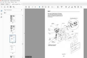
Removal and installation of operator cab glass (stuck glass) 940
Removal and installation of front window assembly 950
Removal and installation of floor frame assembly 957
Electrical system 961
Removal and installation of air conditioner unit assembly 961
Removal and installation of KOMTRAX communication modem assembly 964
Removal and installation of monitor assembly 965
Removal and installation of pump controller assembly 967
90 Diagrams and drawings 969
Contents 970
Hydraulic diagrams and drawings 971
Hydraulic circuit diagram 971
Electrical diagrams and drawings 973
Electrical circuit diagram 973
Connector arrangement diagram 983
INDEX 985
IMAGES PREVIEW OF THE MANUAL:
More products