$45
Komatsu PC290LC-8, PC290NLC-8 Hydraulic Excavator Shop Manual - PDF
Komatsu PC290LC-8, PC290NLC-8 Hydraulic Excavator Shop Manual
FILE DETAILS:
Komatsu PC290LC-8, PC290NLC-8 Hydraulic Excavator Shop Manual
File Format : PDF
Language : English
Printable : Yes
Searchable : Yes
Bookmarked : Yes
Product Code : UEN00001-01
Total Pages : 1050
DESCRIPTION:
Komatsu PC290LC-8, PC290NLC-8 Hydraulic Excavator Shop Manual
HOW TO READ THE SHOP MANUAL:
1. Composition of shop manual:
This shop manual contains the necessary technical information for services performed in a workshop. For ease of understanding, the manual is divided into the following sections.
00. Index and foreword:
This section explains the shop manuals list, table of contents, safety, and basic information.
01. Specification:
This section explains the specifications of the machine.
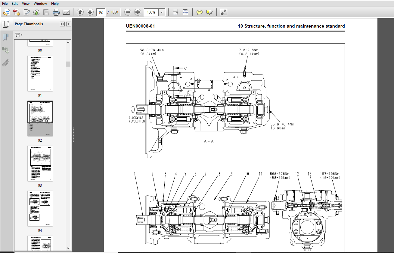
10. Structure, function and maintenance standard:
This section explains the structure, function, and maintenance standard values of each component. The structure and function sub-section explains the structure and function of each component. It serves not only to give an understanding of the structure, but also serves as reference material for troubleshooting. The maintenance standard sub-section explains the criteria and remedies for disassembly and service.
20. Standard value table:
This section explains the standard values for new machine and judgement criteria for testing, adjusting, and troubleshooting. This standard value table is used to check the standard values in testing and adjusting and to judge parts in troubleshooting.
30. Testing and adjusting:
This section explains measuring instruments and measuring methods for testing and adjusting, and method of adjusting each part. The standard values and judgement criteria for testing and adjusting are explained in Testing and adjusting.
40. Troubleshooting:
This section explains how to find out failed parts and how to repair them. The troubleshooting is divided by failure modes. The “S mode” of the troubleshooting related to the engine may be also explained in the Chassis volume and Engine volume. In this case, see the Chassis volume.
50. Disassembly and assembly:
This section explains the special tools and procedures for removing, installing, disassembling, and assembling each component, as well as precautions for them. In addition, tightening torque and quantity and weight of coating material, oil, grease, and coolant necessary for the work are also explained.
90. Diagrams and drawings (chassis volume)/Repair and replacement of parts (engine volume):
- Chassis volume
This section gives hydraulic circuit diagrams and electrical circuit diagrams. - Engine volume
This section explains the method of reproducing, repairing, and replacing parts
TABLE OF CONTENTS:
Komatsu PC290LC-8, PC290NLC-8 Hydraulic Excavator Shop Manual
00 Index and foreword........................................................................................   3
	Index....................................................................................................   3
		Organization list of the shop manual.................................................................   4
		Table of contents....................................................................................   6
00 Index and foreword........................................................................................  15
	Foreword and general information.........................................................................  15
		Foreword and general information.....................................................................  16
			Safety notice....................................................................................  16
			How to read the shop manual......................................................................  20
			Explanation of terms for maintenance standard....................................................  22
			Handling electric equipment and hydraulic component..............................................  24
			How to read electric wire code...................................................................  32
			Method of disassembling and connecting push-pull type coupler....................................  35
			Standard tightening torque table.................................................................  38
			Conversion table.................................................................................  42
01 Specification.............................................................................................  49
	Specification and technical data.........................................................................  49
		Specification and technical data.....................................................................  50
			Specification dimension drawings.................................................................  50
			Working range diagram............................................................................  51
			Specifications...................................................................................  52
			Weight table.....................................................................................  54
			Table of fuel, coolant and lubricants............................................................  56
10 Structure, function and maintenance standard..............................................................  59
	Engine and cooling system................................................................................  59
		Engine and cooling system............................................................................  60
			Engine related parts.............................................................................  60
			Radiator, oil cooler, aftercooler and fuel cooler................................................  61
10 Structure, function and maintenance standard..............................................................  63
	Power train..............................................................................................  63
		Power train..........................................................................................  64
			Power train......................................................................................  64
			Final drive......................................................................................  66
			Swing machinery..................................................................................  68
			Swing circle.....................................................................................  70
10 Structure, function and maintenance standard..............................................................  73
	Undercarriage and frame..................................................................................  73
		Undercarriage and frame..............................................................................  74
			Track frame and recoil spring....................................................................  74
			Idler............................................................................................  76
			Carrier roller...................................................................................  78
			Track roller.....................................................................................  79
			Track shoe.......................................................................................  80
10 Structure, function and maintenance standard..............................................................  85
	Hydraulic system, Part 1.................................................................................  85
		Hydraulic system, Part 1.............................................................................  86
			Hydraulic equipment layout drawing...............................................................  86
			Hydraulic tank and filter........................................................................  88
			Hydraulic pump...................................................................................  90
			Pilot oil filter................................................................................. 112
10 Structure, function and maintenance standard.............................................................. 115
	Hydraulic system, Part 2................................................................................. 115
		Hydraulic system, Part 2............................................................................. 116
			Control valve.................................................................................... 116
			CLSS............................................................................................. 127
			Functions and operation by valve................................................................. 132
			Hydraulic drift prevention valve................................................................. 157
10 Structure, function and maintenance standard.............................................................. 169
	Hydraulic system, Part 3................................................................................. 169
		Hydraulic system, Part 3............................................................................. 171
			Swing motor...................................................................................... 171
			Center swivel joint.............................................................................. 180
			Travel motor..................................................................................... 183
			PPC valve........................................................................................ 196
			Valve control.................................................................................... 218
			ATT EPC Valve Assembly........................................................................... 220
			Solenoid valve................................................................................... 222
			PPC Accumulator.................................................................................. 224
			Return oil filter................................................................................ 225
			Attachment circuit selector valve................................................................ 226
			Quick coupler control valve...................................................................... 228
			Quick coupler control valve...................................................................... 230
			Hydraulic cylinder............................................................................... 232
10 Structure, function and maintenance standard.............................................................. 235
	Work equipment........................................................................................... 235
		Work equipment....................................................................................... 236
			Dimensions of components......................................................................... 236
10 Structure, function and maintenance standard.............................................................. 243
	Cab and its attachments.................................................................................. 243
		Cab and its attachments.............................................................................. 244
			Air conditioner piping........................................................................... 244
10 Structure, function and maintenance standard.............................................................. 247
	Electrical system........................................................................................ 247
		Electrical system.................................................................................... 249
			Engine control................................................................................... 249
			Electrical control system........................................................................ 258
			Monitor system................................................................................... 283
			Sensor........................................................................................... 314
			PPC Levers....................................................................................... 317
			KOMTRAX terminal system.......................................................................... 319
20 Standard value table...................................................................................... 323
	Standard service value table............................................................................. 323
		Standard service value table......................................................................... 324
			Standard value table for engine related parts.................................................... 324
			Standard value table for chassis related parts................................................... 325
30 Testing and adjusting..................................................................................... 337
	Testing and adjusting, Part 1............................................................................ 337
		Testing and adjusting, Part 1........................................................................ 339
			Tools for testing, adjusting, and troubleshooting................................................ 339
			Measuring engine speed........................................................................... 342
			Measuring intake air pressure (boost pressure)................................................... 343
			Checking exhaust gas color....................................................................... 344
			Adjusting valve clearance........................................................................ 345
			Measuring compression pressure................................................................... 347
			Measuring blow-by pressure....................................................................... 349
			Measuring engine oil pressure.................................................................... 350
			Handling fuel system parts....................................................................... 351
			Releasing residual pressure from fuel system..................................................... 351
			Measuring fuel pressure.......................................................................... 352
			Measuring fuel return rate and leakage........................................................... 354
			Bleeding air from fuel circuit................................................................... 356
			Checking fuel circuit for leakage................................................................ 358
			Checking and adjusting air conditioner compressor belt tension................................... 359
			Measuring swing circle bearing clearance......................................................... 360
			Checking and adjusting track shoe tension........................................................ 361
			Measuring and adjusting oil pressure in work equipment, swing, and travel circuits............... 363
			Measuring control circuit basic pressure......................................................... 366
			Measuring and adjusting oil pressure in pump PC control circuit.................................. 367
			Measuring and adjusting oil pressure in pump LS control circuit.................................. 370
			Measuring solenoid valve output pressure......................................................... 374
			Measuring PPC valve output pressure.............................................................. 377
			Adjusting play of work equipment and swing PPC valves............................................ 379
			Measuring and adjusting quick coupler control valve output pressure.............................. 380
			Checking parts which cause hydraulic drift of work equipment..................................... 381
			Releasing residual pressure from hydraulic circuit............................................... 382
			Measuring oil leakage............................................................................ 383
			Bleeding air from each part...................................................................... 386
			Checking cab tipping stopper..................................................................... 388
			Adjusting mirrors................................................................................ 390
30 Testing and adjusting..................................................................................... 393
	Testing and adjusting, Part 2............................................................................ 393
		Testing and adjusting, Part 2........................................................................ 394
			Special functions of machine monitor............................................................. 394
30 Testing and adjusting..................................................................................... 451
	Testing and adjusting, Part 3............................................................................ 451
		Testing and adjusting, Part 3........................................................................ 452
			Handling high-voltage circuit of engine controller............................................... 452
			Preparation work for troubleshooting of electrical system........................................ 453
			Procedure for testing diodes..................................................................... 457
			Pm Clinic service................................................................................ 459
40 Troubleshooting........................................................................................... 467
	General information on troubleshooting................................................................... 467
		General information on troubleshooting............................................................... 468
			Points to remember when troubleshooting.......................................................... 468
			Sequence of events in troubleshooting............................................................ 469
			Check before troubleshooting..................................................................... 470
			Classification and procedures for troubleshooting................................................ 471
			How to read electric wire code................................................................... 475
			Connection table for connector pin numbers....................................................... 478
			T-boxes and T-adapters table..................................................................... 501
40 Troubleshooting........................................................................................... 505
	Troubleshooting by failure code (Display of code), Part 1................................................ 505
		Troubleshooting by failure code (Display of code), Part 1............................................ 507
			Failure codes table.............................................................................. 507
			Before carrying out troubleshooting when failure code is displayed............................... 512
			Information in troubleshooting table............................................................. 516
			Failure code [989L00] Engine Controller Lock Caution 1........................................... 518
			Failure code [989M00] Engine Controller Lock Caution 2........................................... 518
			Failure code [989N00] Engine Controller Lock Caution 3........................................... 519
			Failure code [AA10NX] Air Cleaner Clogging....................................................... 519
			Failure code [AB00KE] Charge Voltage Low......................................................... 520
			Failure code [B@BAZG] Eng Oil Press. Low......................................................... 522
			Failure code [B@BAZK] Eng Oil Level Low.......................................................... 522
			Failure code [B@BCNS] Eng Water Overheat......................................................... 523
			Failure code [B@BCZK] Eng Water Level Low........................................................ 523
			Failure code [B@HANS] Hydr Oil Overheat.......................................................... 524
			Failure code [CA111] EMC Critical Internal Failure............................................... 524
			Failure code [CA115] Eng Ne and Bkup Speed Sens Error............................................ 525
			Failure code [CA122] Chg Air Press Sensor High Error............................................. 526
			Failure code [CA123] Chg Air Press Sensor Low Error.............................................. 528
			Failure code [CA131] Throttle Sensor High Error.................................................. 530
			Failure code [CA132] Throttle Sensor Low Error................................................... 532
			Failure code [CA144] Coolant Temp Sens High Error................................................ 534
			Failure code [CA145] Coolant Temp Sens Low Error................................................. 536
			Failure code [CA153] Chg Air Temp Sensor High Error.............................................. 538
			Failure code [CA154] Chg Air Temp Sensor Low Error............................................... 540
			Failure code [CA155] Chg Air Temp High Speed Derate.............................................. 542
			Failure code [CA187] Sens Supply 2 Volt Low Error................................................ 544
			Failure code [CA221] Ambient Press Sens High Error............................................... 546
			Failure code [CA222] Ambient Press Sens Low Error................................................ 548
			Failure code [CA227] Sens Supply 2 Volt High Error............................................... 550
			Failure code [CA234] Eng Overspeed............................................................... 551
			Failure code [CA238] Ne Speed Sens Supply Volt Error............................................. 552
			Failure code [CA271] IMV/PCV1 Short Error........................................................ 553
			Failure code [CA272] IMV/PCV1 Open Error......................................................... 554
			Failure code [CA322] Inj #1 (L#1) Open/Short Error............................................... 556
			Failure code [CA323] Inj #5 (L#5) Open/Short Error............................................... 558
			Failure code [CA324] Inj #3 (L#3) Open/Short Error............................................... 560
			Failure code [CA325] Inj #6 (L#6) Open/Short Error............................................... 562
			Failure code [CA331] Inj #2 (L#2) Open/Short Error............................................... 564
			Failure code [CA332] Inj #4 (L#4) Open/Short Error............................................... 566
40 Troubleshooting........................................................................................... 569
	Troubleshooting by failure code (Display of code), Part 2................................................ 569
		Troubleshooting by failure code (Display of code), Part 2............................................ 571
			Failure code [CA342] Calibration Code Incompatibility............................................ 571
			Failure code [CA351] Injectors Drive Circuit Error............................................... 572
			Failure code [CA352] Sens Supply 1 Volt Low Error................................................ 574
			Failure code [CA386] Sens Supply 1 Volt High Error............................................... 576
			Failure code [CA428] Water in Fuel Sensor High Error............................................. 578
			Failure code [CA429] Water in Fuel Sensor Low Error.............................................. 580
			Failure code [CA435] Eng Oil Press Sw Error...................................................... 582
			Failure code [CA441] Battery Voltage Low Error................................................... 583
			Failure code [CA442] Battery Voltage High Error.................................................. 586
			Failure code [CA449] Rail Press Very High Error.................................................. 588
			Failure code [CA451] Rail Press Sensor High Error................................................ 590
			Failure code [CA452] Rail Press Sensor Low Error................................................. 592
			Failure code [CA488] Chg Air Temp High Torque Derate............................................. 594
			Failure code [CA553] Rail Press High Error....................................................... 594
			Failure code [CA559] Rail Press Low Error........................................................ 595
			Failure code [CA689] Eng Ne Speed Sensor Error................................................... 596
			Failure code [CA731] Eng Bkup Speed Sens Phase Error............................................. 598
			Failure code [CA757] All Continuous Data Lost Error.............................................. 600
			Failure code [CA778] Eng Bkup Speed Sensor Error................................................. 602
			Failure code [CA1633] KOMNET Datalink Timeout Error.............................................. 604
			Failure code [CA2185] Throt Sens Sup Volt High Error............................................. 606
			Failure code [CA2186] Throt Sens Sup Volt Low Error.............................................. 607
			Failure code [CA2249] Rail Press Very Low Error.................................................. 608
			Failure code [CA2311] IMV Solenoid Error......................................................... 610
			Failure code [CA2555] Grid Htr Relay Volt High Error............................................. 612
			Failure code [CA2556] Grid Htr Relay Volt Low Error.............................................. 614
			Failure code [D19JKZ] Personal Code Relay Abnormality............................................ 616
			Failure code [D862KA] GPS Antenna Discon......................................................... 618
			Failure code [DA25KP] 5V Sensor 1 Power Abnormality.............................................. 619
			Failure code [DA29KQ] Model Selection Abnormality................................................ 626
40 Troubleshooting........................................................................................... 629
	Troubleshooting by failure code (Display of code), Part 3................................................ 629
		Troubleshooting by failure code (Display of code), Part 3............................................ 632
			Failure code [DA2RMC] CAN Discon (Pump Con Detected)............................................. 632
			Failure code [DAFGMC] GPS Module Error........................................................... 634
			Failure code [DAFRMC] CAN Discon (Monitor Detected).............................................. 636
			Failure code [DGH2KB] Hydr Oil Sensor Short...................................................... 638
			Failure code [DHPAMA] F Pump Press Sensor Abnormality............................................ 640
			Failure code [DHPBMA] R Pump Press Sensor Abnormality............................................ 642
			Failure code [DHS3MA] Arm Curl PPC Press Sensor Abnormality...................................... 644
			Failure code [DHS4MA] Bucket Curl PPC Press Sensor Abnormality................................... 646
			Failure code [DHS8MA] Boom Raise PPC Press Sensor Abnormality.................................... 648
			Failure code [DHSAMA] Swing RH PPC Press Sensor Abnormality...................................... 650
			Failure code [DHSBMA] Swing LH PPC Press Sensor Abnormality...................................... 652
			Failure code [DHSDMA] Bucket Dump PPC Press Sensor Abnormality................................... 654
			Failure code [DHX1MA] Overload Sensor Abnormality (Analog)....................................... 656
			Failure code [DW43KA] Travel Speed Sol Discon.................................................... 658
			Failure code [DW43KB] Travel Speed Sol Short..................................................... 660
			Failure code [DW45KA] Swing Brake Sol Discon..................................................... 662
			Failure code [DW45KB] Swing Brake Sol Short...................................................... 664
			Failure code [DW91KA] Travel Junction Sol Discon................................................. 666
			Failure code [DW91KB] Travel Junction Sol Short.................................................. 668
			Failure code [DWA2KA] Service Sol Discon......................................................... 670
			Failure code [DWA2KB] Service Sol Short.......................................................... 671
			Failure code [DWK0KA] 2-stage Relief Sol Discon.................................................. 672
			Failure code [DWK0KB] 2-stage Relief Sol Short................................................... 674
40 Troubleshooting........................................................................................... 677
	Troubleshooting by failure code (Display of code), Part 4................................................ 677
		Troubleshooting by failure code (Display of code), Part 4............................................ 680
			Failure code [DXA8KA] PC-EPC (F) Sol Discon...................................................... 680
			Failure code [DXA8KB] PC-EPC (F) Sol Short....................................................... 682
			Failure code [DXA9KA] PC-EPC (R) Sol Discon...................................................... 684
			Failure code [DXA9KB] PC-EPC (R) Sol Short....................................................... 686
			Failure code [DXE0KA] LS-EPC Sol Discon.......................................................... 688
			Failure code [DXE0KB] LS-EPC Sol Short........................................................... 690
			Failure code [DXE4KA] Service Current EPC Discon................................................. 692
			Failure code [DXE4KB] Service Current EPC Short.................................................. 694
			Failure code [DXE5KA] Merge-divider Main Sol Discon.............................................. 696
			Failure code [DXE5KB] Merge-divider Main Sol Short............................................... 698
			Failure code [DXE6KA] Merge-divider LS Sol Discon................................................ 700
			Failure code [DXE6KB] Merge-divider LS Sol Short................................................. 702
			Failure code [DY20KA] Wiper Working Abnormality.................................................. 704
			Failure code [DY20MA] Wiper Parking Abnormality.................................................. 706
			Failure code [DY2CKA] Washer Drive Discon........................................................ 708
			Failure code [DY2CKB] Washer Drive Short......................................................... 710
			Failure code [DY2DKB] Wiper Drive (For) Short.................................................... 712
			Failure code [DY2EKB] Wiper Drive (Rev) Short.................................................... 714
40 Troubleshooting........................................................................................... 717
	Troubleshooting of electrical system (E-mode)............................................................ 717
		Troubleshooting of electrical system (E-mode)........................................................ 719
			Before carrying out troubleshooting of electrical system......................................... 719
			Information in troubleshooting table............................................................. 721
			E-1 When starting switch turned ON, machine monitor displays nothing............................. 722
			E-2 When starting switch turned ON (before starting engine), basic check item lights up.......... 724
			E-3 Engine does not start (Engine does not turn)................................................. 727
			E-4 Preheater does not operate................................................................... 730
			E-5 Automatic warm-up system does not operate (in cold season)................................... 732
			E-6 All work equipment, swing, and travel mechanism do not move or cannot be locked.............. 734
			E-7 Precaution lights up while engine is running................................................. 736
			E-8 Emergency stop item lights up while engine is running........................................ 741
			E-9 Engine coolant temperature gauge does not indicate normally.................................. 742
			E-10 Hydraulic oil temperature gauge does not indicate normally.................................. 743
			E-11 Fuel level gauge does not indicate normally................................................. 745
			E-12 Contents of display by machine monitor are different from applicable machine................ 747
			E-13 Machine monitor does not display some items................................................. 747
			E-14 Function switch does not work............................................................... 747
			E-15 Auto-decelerator does not operate normally.................................................. 748
			E-16 Working mode does not change................................................................ 749
			E-17 Travel speed does not change................................................................ 750
			E-18 Alarm buzzer cannot be stopped.............................................................. 751
			E-19 Windshield wiper and window washer do not operate........................................... 752
			E-20 Power maximizing function does not operate normally......................................... 754
			E-21 Swing holding brake does not operate normally............................................... 756
			E-22 Travel alarm does not sound or does not stop sounding....................................... 758
			E-23 Air conditioner does not operate normally (including air conditioner abnormality record).... 760
			E-24 When starting switch is turned OFF, service meter is not displayed.......................... 772
			E-25 Machine monitor cannot be set in service mode............................................... 772
			E-26 Monitoring function does not display lever control signal normally.......................... 773
			E-27 KOMTRAX system does not operate normally.................................................... 781
40 Troubleshooting........................................................................................... 783
	Troubleshooting of hydraulic and mechanical system (H-mode).............................................. 783
		Troubleshooting of hydraulic and mechanical system (H-mode).......................................... 786
			System diagram of hydraulic and mechanical system................................................ 786
			Information in troubleshooting table............................................................. 788
			H-1 Speed or power of whole work equipment, swing, and travel is low............................. 789
			H-2 Engine speed lowers extremely or engine stalls............................................... 791
			H-3 Work equipment, swing, and travel systems do not work........................................ 792
			H-4 Abnormal sound comes out from around hydraulic pump.......................................... 792
			H-5 Auto-decelerator does not operate............................................................ 793
			H-6 Fine control performance or response is low.................................................. 793
			H-7 Speed or power of boom is low................................................................ 794
			H-8 Speed or power of arm is low................................................................. 795
			H-9 Speed or power of bucket is low.............................................................. 796
			H-10 Work equipment does not move singly......................................................... 796
			H-11 Hydraulic drift of work equipment is large.................................................. 797
			H-12 Time lag of work equipment is large......................................................... 799
			H-13 When part of work equipment is relieved singly, other parts of work equipment move.......... 799
			H-14 Power maximizing function does not work..................................................... 800
			H-15 In compound operation of work equipment, speed of part loaded more is low................... 800
			H-16 When machine swings and raises boom simultaneously, boom rising speed is low................ 801
			H-17 When machine swings and travels simultaneously, travel speed lowers largely................. 801
			H-18 Machine deviates during travel.............................................................. 802
			H-19 Travel speed is low......................................................................... 803
			H-20 Machine is not steered well or steering power is low........................................ 804
			H-21 Travel speed does not change or travel speed is low/high.................................... 805
			H-22 Travel system does not move (only one side)................................................. 806
			H-23 Upper structure does not swing.............................................................. 807
			H-24 Swing acceleration or swing speed is low.................................................... 809
			H-25 Upper structure overruns remarkably when it stops swinging.................................. 810
			H-26 Large shock is made when upper structure stops swinging..................................... 811
			H-27 Large sound is made when upper structure stops swinging..................................... 811
			H-28 Hydraulic drift of swing is large........................................................... 812
			H-29 Attachment circuit is not changed........................................................... 813
			H-30 Oil flow in attachment circuit cannot be controlled......................................... 813
			Quick coupler.................................................................................... 814
40 Troubleshooting........................................................................................... 817
	Troubleshooting of engine (S-mode)....................................................................... 817
		Troubleshooting of engine (S-mode)................................................................... 819
			Method of using troubleshooting chart............................................................ 819
			S-1 Starting performance is poor................................................................. 822
			S-2 Engine does not start........................................................................ 823
			S-3 Engine does not pick up smoothly............................................................. 826
			S-4 Engine stops during operations............................................................... 827
			S-5 Engine does not rotate smoothly.............................................................. 828
			S-6 Engine lack output (or lacks power).......................................................... 829
			S-7 Exhaust smoke is black (incomplete combustion)............................................... 830
			S-8 Oil consumption is excessive (or exhaust smoke is blue)...................................... 831
			S-9 Oil becomes contaminated quickly............................................................. 832
			S-10 Fuel consumption is excessive............................................................... 833
			S-11 Oil is in coolant (or coolant spurts back or coolant level goes down)....................... 834
			S-12 Oil pressure drops.......................................................................... 835
			S-13 Oil level rises (Entry of coolant/fuel)..................................................... 836
			S-14 Coolant temperature becomes too high (overheating).......................................... 837
			S-15 Abnormal noise is made...................................................................... 838
			S-16 Vibration is excessive...................................................................... 839
50 Disassembly and assembly.................................................................................. 841
	General information on disassembly and assembly.......................................................... 841
		General information on disassembly and assembly...................................................... 842
			How to read this manual.......................................................................... 842
			Coating materials list........................................................................... 844
			Special tool list................................................................................ 847
			Sketches of special tools........................................................................ 852
50 Disassembly and assembly.................................................................................. 855
	Engine and cooling system................................................................................ 855
		Engine and cooling system............................................................................ 856
			Removal and installation of fuel supply pump assembly............................................ 856
			Removal and installation of fuel injector assembly............................................... 858
			Removal and installation of engine front seal.................................................... 865
			Removal and installation of engine rear seal..................................................... 868
			Removal and installation of cylinder head assembly............................................... 871
			Removal and installation of radiator assembly.................................................... 883
			Removal and installation of hydraulic oil cooler assembly........................................ 886
			Removal and installation of aftercooler assembly................................................. 888
			Removal and installation of fuel cooler assembly................................................. 890
			Removal and installation of engine and hydraulic pump assembly................................... 891
50 Disassembly and assembly.................................................................................. 901
	Power train.............................................................................................. 901
		Power train.......................................................................................... 902
			Removal and installation of final drive assembly................................................. 902
			Disassembly and assembly of final drive assembly................................................. 903
			Removal and installation of swing motor and swing machinery assembly............................. 912
			Disassembly and assembly of swing motor and swing machinery assembly............................. 914
			Removal and installation of swing circle assembly................................................ 923
50 Disassembly and assembly.................................................................................. 925
	Undercarriage and frame.................................................................................. 925
		Undercarriage and frame.............................................................................. 926
			Disassembly and assembly of carrier roller assembly.............................................. 926
			Disassembly and assembly of track roller assembly................................................ 927
			Disassembly and assembly of idler assembly....................................................... 928
			Disassembly and assembly of recoil spring assembly............................................... 931
			Removal and installation of sprocket............................................................. 933
			Expansion and installation of track shoe assembly................................................ 934
			Removal and installation of revolving frame assembly............................................. 936
			Removal and installation of counterweight assembly............................................... 938
50 Disassembly and assembly.................................................................................. 941
	Hydraulic system......................................................................................... 941
		Hydraulic system..................................................................................... 942
			Removal and installation of center swivel joint assembly......................................... 942
			Disassembly and assembly of center swivel joint assembly......................................... 944
			Removal and installation of hydraulic tank assembly.............................................. 945
			Removal and installation of control valve assembly............................................... 948
			Disassembly and assembly of control valve assembly............................................... 953
			Removal and installation of hydraulic pump assembly.............................................. 957
			Removal and installation of oil seal in hydraulic pump input shaft............................... 961
			Disassembly and assembly of work equipment PPC valve assembly.................................... 962
			Disassembly and assembly of travel PPC valve assembly............................................ 963
			Disassembly and assembly of hydraulic cylinder assembly.......................................... 964
			Disassembly and Assembly of Quick Coupler Valve.................................................. 970
50 Disassembly and assembly.................................................................................. 973
	Work equipment........................................................................................... 973
		Work equipment....................................................................................... 974
			Removal and installation of work equipment assembly.............................................. 974
50 Disassembly and assembly.................................................................................. 979
	Cab and its attachments.................................................................................. 979
		Cab and its attachments.............................................................................. 980
			Removal and installation of operator's cab assembly.............................................. 980
			Removal and installation of operator cab glass (stuck glass)..................................... 983
			Removal and installation of front window assembly................................................ 993
			Removal and installation of floor frame assembly.................................................1000
50 Disassembly and assembly..................................................................................1005
	Electrical system........................................................................................1005
		Electrical system....................................................................................1006
			Removal and installation of air conditioner unit assembly........................................1006
			Removal and installation of KOMTRAX communication modem assembly.................................1009
			Removal and installation of monitor assembly.....................................................1010
			Removal and installation of pump controller assembly.............................................1012
			Removal and installation of engine controller assembly...........................................1013
90 Diagrams and drawings.....................................................................................1015
	Hydraulic diagrams and drawings..........................................................................1015
		Hydraulic diagrams and drawings (For PC290-8 K50001 ~ K50104)........................................1017
			Hydraulic circuit diagram 1/2....................................................................1017
			Hydraulic circuit diagram 2/2....................................................................1019
		Hydraulic diagrams and drawings (For PC290-8 K50105 and up)).........................................1021
			Hydraulic circuit diagram 1/2....................................................................1021
			Hydraulic circuit diagram 2/2....................................................................1023
90 Diagrams and drawings.....................................................................................1027
	Electrical diagrams and drawings.........................................................................1027
		Electrical circuit diagram (For PC290-8 K50001 ~ K50104).............................................1029
			Electrical circuit diagram (1/5).................................................................1029
			Electrical circuit diagram (2/5).................................................................1031
			Electrical circuit diagram (3/5).................................................................1033
			Electrical circuit diagram (4/5).................................................................1035
			Electrical circuit diagram (5/5).................................................................1037
		Electrical diagrams and drawings (For PC290 K50105 and up)...........................................1039
			Electrical circuit diagram (1/5).................................................................1039
			Electrical circuit diagram (2/5).................................................................1041
			Electrical circuit diagram (3/5).................................................................1043
			Electrical circuit diagram (4/5).................................................................1045
			Electrical circuit diagram (5/5).................................................................1047
IMAGES PREVIEW OF THE MANUAL:
More products