$42
Komatsu PC3000-1 Hydraulic Mining Excavator Operation & Maintenance Manual OMPC30006202 – PDF
Komatsu PC3000-1 Hydraulic Mining Excavator Operation & Maintenance Manual OMPC30006202 – PDF DOWNLOAD
FILE DETAILS:
Komatsu PC3000-1 Hydraulic Mining Excavator Operation & Maintenance Manual OMPC30006202 – PDF DOWNLOAD
Language : English
Pages : 378
Downloadable : Yes
File Type : PDF
Size: 13.9 MB
IMAGES PREVIEW OF THE MANUAL:
DESCRIPTION:
Komatsu PC3000-1 Hydraulic Mining Excavator Operation & Maintenance Manual OMPC30006202 – PDF DOWNLOAD
SERIAL NUMBERS PC3000-1 6202
The Komatsu PC3000-1 Hydraulic Mining Excavator Operation & Maintenance Manual OMPC30006202 is a comprehensive guide that provides detailed information on the operation and maintenance of the Komatsu PC3000-1 Hydraulic Mining Excavator. This manual is designed to be used by operators and maintenance personnel who are responsible for the safe and efficient operation of the machine.
- The manual is divided into several sections, each providing valuable information on specific aspects of the machine. The first section provides an overview of the machine’s features and specifications, including its engine, hydraulic system, electrical system, and structural components. This section also includes information on the machine’s safety features and important safety guidelines for operating the machine.
- The second section of the manual provides a detailed description of the machine’s controls and how to operate them. This includes information on the operation of the machine’s boom, bucket, and cab, as well as its various sensors, gauges, and monitors. This section also includes information on how to start and stop the machine, as well as how to use the various modes and settings available.
- The third section of the manual provides information on maintenance and servicing of the machine. This section includes recommended maintenance schedules, procedures for routine maintenance, and troubleshooting procedures for identifying and fixing common problems. It also includes information on how to service the machine’s engine, hydraulic system, and electrical system, as well as how to perform inspections and replace worn or damaged parts.
- The fourth section of the manual provides information on troubleshooting and diagnosing problems with the machine. This includes procedures for identifying and fixing common problems with the engine, hydraulic system, electrical system, and other components of the machine.
- The manual also includes several appendices that provide additional information on topics such as specifications and dimensions, hydraulic system diagrams, and electrical system diagrams. These appendices can be especially useful for mechanics and technicians who are responsible for maintaining and servicing the machine.
- Overall, the Komatsu PC3000-1 Hydraulic Mining Excavator Operation & Maintenance Manual OMPC30006202 is an essential resource for anyone involved in the operation and maintenance of this machine. Its detailed information and step-by-step procedures can help ensure the safe and efficient use of the machine in mining operations, and its troubleshooting procedures can help minimize downtime and increase productivity.
TABLE OF CONTENTS:
Komatsu PC3000-1 Hydraulic Mining Excavator Operation & Maintenance Manual OMPC30006202 – PDF DOWNLOAD
Main Menu……………………………………………………………………… 0
Cover…………………………………………………………………………. 1
Introduction…………………………………………………………………… 2
Part 1 – Operation Manual……………………………………………………….. 8
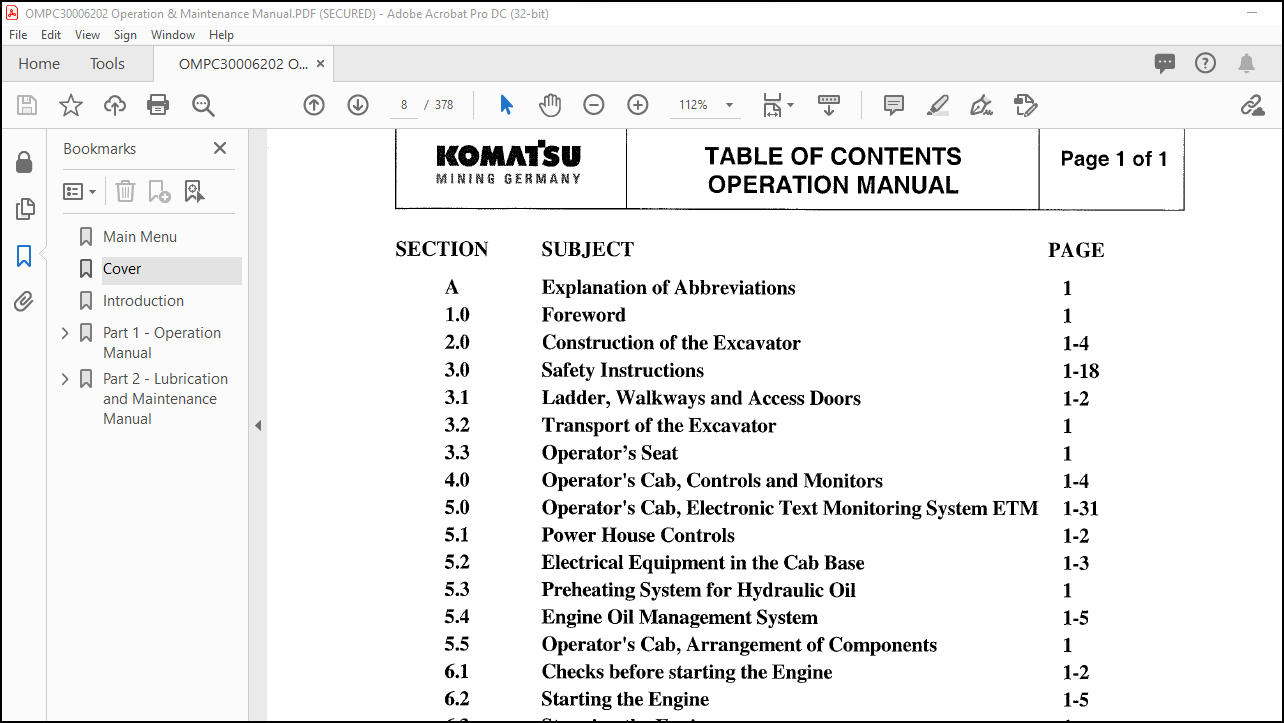
Table of Contents – Operation Manual………………………………………….. 8
Section A – Explanation of Abbreviations Used in this Manual…………………….. 10
Section 1.0 – Foreward………………………………………………………. 12
Section 2.0 – Construction of the Excavator……………………………………. 14
2. – Overall View……………………………………………………….. 14
2.1 – Superstructure…………………………………………………….. 16
2.3 – Attachment………………………………………………………… 20
Backhoe Attachment…………………………………………………… 20
Section 3.0 – Safety Instructions…………………………………………….. 22
Fundamental Safety Instructions…………………………………………… 23
1.1 – Warnings and Symbols……………………………………………. 23
1.2 – Basic Operation and Designated Use of Hydraulic Excavator…………… 23
1.3 – Organizational Measures…………………………………………. 24
1.4 – Selection and Qualification of Personal…………………………… 26
1.5 – Safety Instructions Governing Specific Operational Phases…………… 27
1.6 – Warning of Special Dangers………………………………………. 32
1.7 – Transporting and Towing – Recommissioning…………………………. 35
1.8 – Special Safety Equipment………………………………………… 36
Safety Harness………………………………………………………….. 38
Instructions for Use…………………………………………………. 38
Prior to Using Harness……………………………………………….. 40
Recommendations for Use of Holding Hooks and Hold-Back Hooks……………… 42
Instructions for Use of Strap-Type Fall Absorber………………………… 42
Section 3.1 – Ladder, Walkways, and Access Doors……………………………….. 44
Superstructure………………………………………………………….. 44
Sea Protection Covers……………………………………………………. 47
Section 3.2 – Transport of Excavator………………………………………….. 48
Short Transport with Calm Sea Conditions Drawing……………………………. 49
Long Transport with Rough Sea Conditions Drawing……………………………. 50
Location of Plug Socket for Hydraulic Oil Heating System…………………….. 51
Section 3.3 – Operator’s Seat………………………………………………… 54
Section 4.0 – Operator’s Cab – Controls and Monitors……………………………. 56
Control Levers and Control Pedals…………………………………………. 56
Safety Circuit for Controls………………………………………………. 56
Switch Board……………………………………………………………. 60
Instruments and Pontoon Controls………………………………………….. 62
Section 5.0 – Electronic Text Monitoring System Komatsu ETM……………………… 64
Introduction……………………………………………………………. 64
Further Features of the ETM System…………………………………….. 64
Messages are Divided into Two Main Groups………………………………. 64
Function of the Keys (1 to 8) of Keyboard………………………………. 66
System Components……………………………………………………. 68
Switches for Adjustment of the ETM…………………………………….. 70
Message Classification……………………………………………….. 70
Functions of the ETM System…………………………………………… 72
Display the Content of Record (PROTOCOL) Memory…………………………. 78
Display the Content of Static Memory…………………………………… 80
Print Out Content of Static Memory…………………………………….. 82
Print Out Content of Record (PROTOCOL) Memory…………………………… 82
Change-over from English to German Language…………………………….. 88
Change-over from German to English Language…………………………….. 88
Several Massage Conditions Occur at Same Time…………………………… 90
Setting the Display Unit……………………………………………… 92
Erase Record (PROTOCOL) and STATISTICS Memory…………………………… 94
Return to System Level……………………………………………….. 96
Setting Screen Brightness…………………………………………….. 96
Table of Messages……………………………………………………. 97
Basic Display (Message Page no. 0)…………………………………. 97
Message Page Number 1 to 5………………………………………… 97
Message Page Number 6 to 11……………………………………….. 98
Message Page Number 12 to 18………………………………………. 99
Message Page Number 19 to 26……………………………………….100
Message Page Number 27 to 30……………………………………….101
Message Page Number 31 to 38……………………………………….102
Message Page Number 39 to 44……………………………………….103
Message Page Number 45 to 52……………………………………….104
Message Page Number 53 to 64……………………………………….105
Grouping Messages According to their Priority……………………………107
1st Priority Group………………………………………………..107
2nd Priority Group………………………………………………..108
3rd Priority Group………………………………………………..108
4th Priority Group………………………………………………..109
Explanation of the Statics Print-Out……………………………………110
Time Diagram of Statics Print………………………………………….111
Section 5.1 – Power House Controls…………………………………………….114
Section 5.2 – Electrical Equipment in Cab Base………………………………….118
Main Switch X2 in Cab Base………………………………………………..120
Diagnostic Fault Codes of Engine Centry System………………………………120
Switch Box X7 for Cab Heating and Air Conditioning…………………………..122
Section 5.3 – Preheating System for Hydraulic Oil……………………………….124
General…………………………………………………………………124
Operating the Heating System………………………………………………124
Section 5.4 – Engine Oil Management System……………………………………..126
General…………………………………………………………………126
Centinel Diagnostic Lamps…………………………………………………128
Check Centinel Diagnostic Lamps for Faults………………………………….128
Clearing Active Faults and Reset the Centinel System…………………………130
Resetting the Centinel System is Necessary………………………………….130
Check the Centinel System for Proper Operation………………………………130
Calibration Plug for Engine Oil Quality…………………………………….130
Oil Burning System Centinel Combined with Reverse System……………………..131
Eliminator Engine Oil Filter………………………………………………132
Section 5.5 – Operator’s Cab Arrangement of Components…………………………..134
Section 6.1 – Ceheck Before Starting the Engine…………………………………136
Section 6.2 – Starting the Engine……………………………………………..140
Before Starting………………………………………………………….140
Starting Procedure……………………………………………………….140
Cold Weather Starting…………………………………………………….142
After Starting…………………………………………………………..142
Automatic Engine Shut-Down System (Safety Chain)…………………………….144
Untitled………………………………………………………………..146
Engine Warm-Up…………………………………………………………..146
Hydraulic Oil Warm-Up…………………………………………………….146
Hydraulic Oil Viscosity and Temperature Chart……………………………….148
Section 6.3 – Stopping the Engine……………………………………………..150
Stopping Procedure……………………………………………………….150
Section 6.4 – Pontoon Operation……………………………………………….152
Warping of the Pontoon……………………………………………………154
Float Position of Backhoe Attachment……………………………………….154
Determination of Directions……………………………………………….154
Shut-off Cocks for the Pontoon Hydraulic System……………………………..156
Section 6.5 – Slewing and Braking the Superstructure…………………………….158
6.5.1 – Rotating the Superstructure………………………………………..158
6.5.2 – Swing Angle Limitation System………………………………………158
6.5.3 – Braking the Superstructure…………………………………………158
6.5.4 – Swing Parking Brake……………………………………………….160
Section 6.6 – Working with the Attachment………………………………………162
Section 6.7 – Combined Operation Cycles………………………………………..166
Section 6.8 – Operating the Heater, Ventilation, and Air Conditioning……………..168
Heating…………………………………………………………………168
Air Conditioning (Special Equipment………………………………………..170
Combined Operation of Air Conditioning and Heating…………………………..170
Section 6.11 – Automatic Lubrication Systems……………………………………172
Central Lubrication System and Swing Ring Gear Lubrication System……………..172
Controls of Automatic Lubrication Systems…………………………………..172
Factory Adjustments………………………………………………………174
Section 6.13 – Fire Detection and Suppression System (Special Equipment)…………..176
Section 6.15 – Transfer Pump for Hydraulic Oil Reservoir…………………………184
Functions of the Transfer Pump…………………………………………….184
Transfer Procedure……………………………………………………….186
Section 7.0 – Working Instructions…………………………………………….190
Excavator Operation………………………………………………………190
Barge Warping……………………………………………………………190
Pontoon Warping………………………………………………………….192
Maintaining the Pontoon in the Flow………………………………………..192
Slowing Down Pontoon Motions………………………………………………192
Working Ashore or at Banks from the Pontoon…………………………………192
Working in Shallow Waters…………………………………………………192
Depositing the Attachment During Working Breaks……………………………..194
Section 7.1 – Emergency Operation System……………………………………….196
Section 9.0 – Refueling the Excavator………………………………………….198
Section 10.0 – Exchange of Attachment and/or Components………………………….200
Part 2 – Lubrication and Maintenance Manual………………………………………..202
Table of Contents – Lubrication and Maintenance Manual…………………………..202
Section 1.0 – Foreward……………………………………………………….204
Section Contents…………………………………………………………204
Definitions……………………………………………………………..205
Section 1.1 – Fire Prevention…………………………………………………208
Section 1.2 – Repair Welding………………………………………………….212
Section 2.0 – Safety Instructions……………………………………………..220
Section 3.0 – Fuel and Lubricants……………………………………………..222
Section 4.0 – Filling Capacities………………………………………………224
Section 5.0 – Lubrication and Maintenance Schedule………………………………226
5.1 – Initial Servicing…………………………………………………..226
5.2 – Periodic Servicing Intervals…………………………………………226
Service Interval Chart………………………………………………..227
Replacement of Hydraulic Hose Lines…………………………………….232
Inspection of Hydraulic Hose Lines……………………………………..232
5.3 – Extended Service Intervals for Engines with Engine Oil Management System….234
Servicing Intervals…………………………………………………..234
Every 10 Operating Hours…………………………………………..234
Every 500 Operating Hours………………………………………….236
Every 4000 Operating Hours…………………………………………236
Engine Oil Reserve Tank……………………………………………236
5.3.1 – Resetting of Engine Oil Burning System Centinel…………………..238
5.4 – Maintenance of Engine……………………………………………….238
5.5 – Maintenance of Eliminator Oil Filtration System………………………..238
Lubrication Point and Maintence Chart………………………………………239
Section 6.1 – Every 10 Operating Hours or Daily…………………………………242
1. – Visual Inspection……………………………………………………242
1.1 – Central Lubrication System……………………………………….246
Backhoe Attachment………………………………………………..246
Bullclam Bucket Attachment…………………………………………248
Slweing Connection………………………………………………..250
1.2 – Grease Injectors, Corrective Actions………………………………250
1.3 – Check Slew Ring Teeth for Proper Lubrication……………………….252
2. – Maintenance of Engines……………………………………………….254
3. – Lubrication of Attachment…………………………………………….254
3.1 – Lubrication of Backhoe Attachment…………………………………254
3.2 – Lubrication of Front Loader Attachment…………………………….254
4. – Lubrication of Slewing Connection……………………………………..256
5. – Engine Air Cleaners………………………………………………….258
6. – Not Used……………………………………………………………258
7. – Radiator – Check Coolant Level………………………………………..260
8. – Track Groups………………………………………………………..260
9. – Fuel System, Water Separator………………………………………….260
Section 6.2 – Every 50 Operating Hours or Weekly………………………………..262
10. – Slew Gear and Motor Adapter Housing…………………………………..262
11. – Not Used…………………………………………………………..264
12. – Pump Distributor Geat (PTO) and Oil Reservoirs…………………………264
13. – Radiator and Hydraulic Oil Coolers……………………………………268
14. – Air Conditioning……………………………………………………268
15. – Maintenance of Engines………………………………………………268
Section 6.3 – Every 250 Operating Hours or Monthly………………………………270
50. – Engine…………………………………………………………….270
51. – Drive Belts………………………………………………………..270
52. – Not Used…………………………………………………………..278
53. – Not Used…………………………………………………………..278
54. – Hydraulic Oil Cooler – Lubricate Fan Bearings………………………….278
55. – Not Used…………………………………………………………..278
56. – Not Used…………………………………………………………..278
57. – Compressor for Signal Horn…………………………………………..280
58. – Automatic Lubrication Systems, Clean In-Line-Grease-Filters……………..282
59. – Air Cleaner for Operator’s Cab……………………………………….284
60. – Air Conditioning……………………………………………………284
61. – Not Used…………………………………………………………..284
62. – Not Used…………………………………………………………..284
63. – Air Conditioning Refrigerant Compressor……………………………….286
Section 6.4 – Every 500 Operating Hours or Every 3 Months………………………..288
70. – Engine…………………………………………………………….288
71. – Batteries………………………………………………………….288
72. – Fuel Tank, Drain Water and Sediments………………………………….290
73. – Flexible Drive Coupling……………………………………………..292
74. – Rotary Distributor Lubrication……………………………………….294
Section 6.5 – Every 1000 Operating Hours or Every 6 Months……………………….296
80. – High-Strength Bolt Connections……………………………………….296
Bolt Torque Chart………………………………………………………..320
81. – Maintenance of Engines………………………………………………322
82. – Hydraulic System……………………………………………………322
83. – Pump Distributor Gears, Slew Gears, and Travel Gears……………………336
84. – Compressor for Signal Horn…………………………………………..338
85. – Not Used…………………………………………………………..338
86. – Air Conditioning……………………………………………………338
Section 6.6 – Every 2000 Operating Hours or Yearly………………………………340
100. – Hydraulic System…………………………………………………..340
Section 6.7 – Every 3000 operating operating Hours but at Least Once a Year………..348
111. – Slew Gear and Motor Adapter Housing………………………………….348
111. – Pump Distributor Gear (PTO)…………………………………………352
Section – 6.8 – When Necessary………………………………………………..356
120. – Servicing the Engine Air Cleaners……………………………………356
121. – Additional Fuel System Water Separator……………………………….362
122. – Slew Gear…………………………………………………………364
123. – Automatic Lubrication Systems with Replaceable Grease Barrels…………..366
124. – Not Used………………………………………………………….368
125. – Not Used………………………………………………………….368
126. – Not Used………………………………………………………….368
127. – Not Used………………………………………………………….368
128. – Hydraulic System…………………………………………………..368
129. – Cold Starting Aid, Replace Fluid Cylinder…………………………….368
130. – Electrical Switch Board (X2)………………………………………..370
Section 7.0 – Excavator Storage……………………………………………….372
General…………………………………………………………………372
1. Preparing for Storage………………………………………………….372
2. One Month Repetitive Service Peroid……………………………………..373
3. Six Month Repetitive Service Period……………………………………..373
4. Preparing for Operation………………………………………………..374
Section 8.0 – Troubleshooting…………………………………………………376
General…………………………………………………………………376
Engine………………………………………………………………….376
Hydraulic System…………………………………………………………377
Travel and Slew Gears…………………………………………………….378
Crawler Tracks…………………………………………………………..378
More products