$35
Komatsu PC3000-1 Hydraulic Mining Shovel Shop Manual SMPC30006171 – PDF DOWNLOAD
Komatsu PC3000-1 Hydraulic Mining Shovel Shop Manual SMPC30006171 – PDF DOWNLOAD
FILE DETAILS:
Komatsu PC3000-1 Hydraulic Mining Shovel Shop Manual SMPC30006171 – PDF DOWNLOAD
Language : English
Pages : 479
Downloadable : Yes
File Type : PDF
Size: 17.5 MB
IMAGES PREVIEW OF THE MANUAL:
DESCRIPTION:
Komatsu PC3000-1 Hydraulic Mining Shovel Shop Manual SMPC30006171 – PDF DOWNLOAD
SERIAL NUMBERS PC3000-1 6171
The Komatsu PC3000-1 Hydraulic Mining Shovel Shop Manual SMPC30006171 is a comprehensive guide that provides in-depth information on the maintenance and repair of the Komatsu PC3000-1 Hydraulic Mining Shovel. This manual is designed to be used by mechanics and technicians who are responsible for servicing and repairing the machine.
- The manual is divided into several sections, each providing valuable information on specific aspects of the machine. The first section provides an overview of the machine and its specifications, including its engine, hydraulic system, electrical system, and structural components. This section also includes information on the safety features of the machine and important safety guidelines for working on the machine.
- The second section of the manual provides detailed information on the maintenance and servicing of the machine. This includes recommended maintenance schedules, procedures for routine maintenance, and troubleshooting procedures for identifying and fixing common problems. This section also includes information on how to service the machine’s engine, hydraulic system, and electrical system, as well as how to perform inspections and replace worn or damaged parts.
- The third section of the manual provides detailed information on the repair and replacement of components and systems. This includes step-by-step procedures for disassembling and reassembling the machine, as well as instructions for repairing or replacing specific components such as the engine, hydraulic system, electrical system, and structural components.
- The fourth section of the manual provides information on testing and adjusting the machine’s components and systems. This includes procedures for testing and adjusting the engine, hydraulic system, electrical system, and other components of the machine to ensure proper operation and performance.
- The manual also includes several appendices that provide additional information on topics such as specifications and dimensions, hydraulic system diagrams, and electrical system diagrams. These appendices can be especially useful for mechanics and technicians who are responsible for maintaining and repairing the machine.
- Overall, the Komatsu PC3000-1 Hydraulic Mining Shovel Shop Manual SMPC30006171 is an essential resource for anyone involved in the maintenance and repair of this machine. Its detailed information and step-by-step procedures can help ensure the safe and efficient operation of the machine, and its troubleshooting procedures can help minimize downtime and increase productivity.
TABLE OF CONTENTS:
Komatsu PC3000-1 Hydraulic Mining Shovel Shop Manual SMPC30006171 – PDF DOWNLOAD
Main Menu…………………………………………………………… 0
Cover………………………………………………………………. 1
Introduction………………………………………………………… 2
Symbols…………………………………………………………….. 3
Foreword……………………………………………………………. 4
Table of Contents……………………………………………………. 6
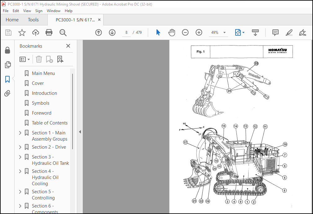
Section 1 – Main Assembly Groups………………………………………. 7
Table of Contents, Section 1………………………………………. 7
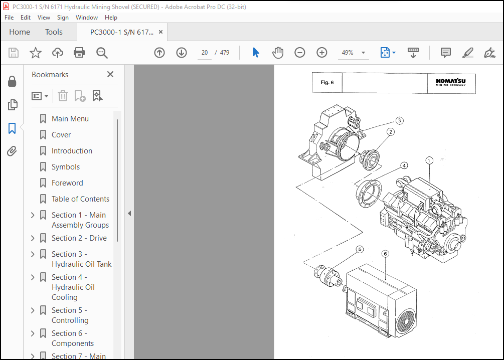
General Layout……………………………………………….. 9
Drive……………………………………………………….. 11
Control Blocks, Slew Gear……………………………………… 13
Undercarriage, Travel Drive……………………………………. 15
Driver’s Cab…………………………………………………. 17
Section 2 – Drive……………………………………………………. 19
Table of Contents, Section 2………………………………………. 19
Prime Drive Assembly………………………………………….. 21
Engine Mounts………………………………………………… 23
Fan Drive and Cooler Assy……………………………………… 25
Coupling…………………………………………………….. 27
Air Filter…………………………………………………… 29
Pump Distributor Gear…………………………………………. 31
Pump Spline – Lubrication……………………………………… 33
PTO – Gear Ludrication………………………………………… 35
Section 3 – Hydraulic Oil Tank………………………………………… 41
Table of Contents, Section 3………………………………………. 41
Main Oil Tank………………………………………………… 43
Return and Leak Oil Filter…………………………………….. 45
Breather Filter………………………………………………. 47
Location of Pressure Switches and Sensors……………………….. 49
Section 4 – Hydraulic Oil Cooling……………………………………… 51
Table of Contents, Section 4………………………………………. 51
General……………………………………………………… 53
Hydraulic Oil Cooling Circuit………………………………….. 55
Measuring / Setting the Back Pressure Valve……………………… 57
Fan Drive……………………………………………………. 61
Axial Piston Pump…………………………………………….. 65
Measuring and Setting of the Fan Speed………………………….. 67
Function Check for RPM-Control…………………………………. 71
Section 5 – Controlling………………………………………………. 73
Table of Contents, Section 5………………………………………. 73
Pilot Pressure Supplu…………………………………………. 75
General………………………………………………….. 75
Function…………………………………………………. 77
Checks and Adjustment of Pilot Pressure…………………………. 79
Measuring and Adjustment of Control Pressure…………………….. 81
Checking of Accumulator Function……………………………. 81
Checking of Accumulator Pre-charge Pressure………………….. 81
Travel Parking Brake………………………………………….. 83
Function Check of Travel Parking Brake………………………….. 85
Slew Parking (House) Brake…………………………………….. 87
Section 6 – Components……………………………………………….. 89
Table of Content…………………………………………………. 89
Main Control Blocks and High Pressure Filter (Bull-Clam Attachment…. 91
Main Control Blocks and High Pressure Filter (Back Hoe Attachment….. 93
Distributor Manifold (Bull-Clam Attachment)……………………… 95
Distributor Manifold (Back Hoe Attachment……………………….. 97
Restrictor Block with Pressure Valve……………………………. 99
Restrictor Block………………………………………………101
Anti Cavitation Valve Block…………………………………….103
Proportional Solenoid Valve…………………………………….105
Pressure Filter……………………………………………….107
Control Blocks………………………………………………..109
Control Blocks and Valves…………………………………..111
Valve at the Control Block………………………………….115
Load Holding Valve…………………………………………117
Travel Brake Valve…………………………………………….119
Pressure Reducing Valve………………………………………..121
Directional Control Valve (Solenoid Valve)……………………….123
Hydraulic Cylinder…………………………………………….125
Auxiliary Pumps, Fan Drive……………………………………..127
Auxiliary Gear Pumps…………………………………………..129
Slew Ring…………………………………………………….131
Section 7 – Main Hydraulic Pumps and Pump Regulation……………………..133
Table of Content………………………………………………….133
Main Hydraulic Pump A7V / HD D………………………………….135
SL-Bearing……………………………………………………139
Function of the Pump Governor…………………………………..141
Pump Bearing Lubrication……………………………………….147
Pump Governor Adjustments………………………………………151
Pump Regulation, General……………………………………….161
Determination of Peak Point (Engine Performance Test)……………..167
Hydraulic Regulation Adjustment, Stop Gap Operation……………….169
Detailed Explanation for Electronic Pump Regulation……………….171
Adjustments / Checks for Electronic Pump Regulation……………….173
Adjusting the RPM Sensor (MPU)………………………………….175
Adjustments at the ELL – Module, Normal Fine Tuning……………….177
Checks / Function Test / Fault Finding at JOBSITE…………………181
EPM – Module, Function and Test…………………………………183
ERM – Module, Function and Test…………………………………185
ELL – Module, Function and Test…………………………………189
Amplifier Module, Function and Test……………………………..193
Simplified Trouble Shooting of Electronic Regulation………………195
Section 8 – Operating Hydraulic………………………………………..199
Table of Content………………………………………………….199
Hydraulic for Attachment Cylinder……………………………….201
Adjustments for Attachment Cylinder Hydraulic…………………….205
Slew Circuit, General………………………………………….223
Slew Motor……………………………………………………227
Slew Gear and House Brake………………………………………231
Slew Brake Valve………………………………………………235
Slew Function…………………………………………………240
Checks and Adjustments…………………………………………251
Travel Citcuit………………………………………………..259
Rotary Distributor…………………………………………….263
Travel Motor (Axial Piston Motor A2FM)…………………………..265
Travel Gear and House Brake…………………………………….269
Travel Gear……………………………………………….269
Travel Gear House Brake…………………………………….271
Travel, Function………………………………………………273
Anti-Cavitation Circuit………………………………………..277
Adjustments / Checks…………………………………………..279
Section 9 – Hydraulic Tank Tension System……………………………….285
Table of Content………………………………………………….285
Hydraulic Track Tension System………………………………….287
Function………………………………………………….289
Pressure Increasing Valve…………………………………..293
Pressure Relief Valve, Direct Operated……………………….295
Adjustments / Pressure Checks……………………………….297
Section 10 – Hints for the Hydraulic Circuit Diagram……………………..305
Table of Content………………………………………………….305
Hints for Reading Circuit Diagrams………………………………309
Legend of the Hydraulic Circuit Diagram………………………….310
Pressure Check Points………………………………………….314
How to Read the Circuit Diagram…………………………………316
Hydraulic Diagram (1/3)……………………………………………317
Hydraulic Diagram (2/3)……………………………………………318
Hydraulic Diagram (3/3)……………………………………………319
Section 11 – Hints for the Electric Circuit Diagram………………………321
Table of Content………………………………………………….321
Markings of Electrical Components in Circuit Diagrams……………..323
Symbols………………………………………………………325
KGM Circuit Diagrams…………………………………………..329
General Information………………………………………..329
Explanation of the Drawing Concept…………………………..331
Terminal Plans…………………………………………….333
Location of Main Terminal Boxes and Important Components……….335
Reading a Circuit Diagram…………………………………..337
Adjustments…………………………………………………..341
Component List / Function………………………………………342
Electrical Diagrams……………………………………………….348
Electrical Diagrams – 897 818 40 (1/49)………………………….348
Electrical Diagrams – 897 818 40 (2/49)………………………….349
Electrical Diagrams – 897 818 40 (3/49)………………………….350
Electrical Diagrams – 897 818 40 (4/49)………………………….351
Electrical Diagrams – 897 818 40 (5/49)………………………….352
Electrical Diagrams – 897 818 40 (6/49)………………………….353
Electrical Diagrams – 897 818 40 (7/49)………………………….354
Electrical Diagrams – 897 818 40 (8/49)………………………….355
Electrical Diagrams – 897 818 40 (9/49)………………………….356
Electrical Diagrams – 897 818 40 (10/49)…………………………357
Electrical Diagrams – 897 818 40 (11/49)…………………………358
Electrical Diagrams – 897 818 40 (12/49)…………………………359
Electrical Diagrams – 897 818 40 (13/49)…………………………360
Electrical Diagrams – 897 818 40 (14/49)…………………………361
Electrical Diagrams – 897 818 40 (15/49)…………………………362
Electrical Diagrams – 897 818 40 (16/49)…………………………363
Electrical Diagrams – 897 818 40 (17/49)…………………………364
Electrical Diagrams – 897 818 40 (18/49)…………………………365
Electrical Diagrams – 897 818 40 (19/49)…………………………366
Electrical Diagrams – 897 818 40 (20/49)…………………………367
Electrical Diagrams – 897 818 40 (21/49)…………………………368
Electrical Diagrams – 897 818 40 (22/49)…………………………369
Electrical Diagrams – 897 818 40 (23/49)…………………………370
Electrical Diagrams – 897 818 40 (24/49)…………………………371
Electrical Diagrams – 897 818 40 (25/49)…………………………372
Electrical Diagrams – 897 818 40 (26/49)…………………………373
Electrical Diagrams – 897 818 40 (27/49)…………………………374
Electrical Diagrams – 897 818 40 (28/49)…………………………375
Electrical Diagrams – 897 818 40 (29/49)…………………………376
Electrical Diagrams – 897 818 40 (30/49)…………………………377
Electrical Diagrams – 897 818 40 (31/49)…………………………378
Electrical Diagrams – 897 818 40 (32/49)…………………………379
Electrical Diagrams – 897 818 40 (33/49)…………………………380
Electrical Diagrams – 897 818 40 (34/49)…………………………381
Electrical Diagrams – 897 818 40 (35/49)…………………………382
Electrical Diagrams – 897 818 40 (36/49)…………………………383
Electrical Diagrams – 897 818 40 (37/49)…………………………384
Electrical Diagrams – 897 818 40 (38/49)…………………………385
Electrical Diagrams – 897 818 40 (39/49)…………………………386
Electrical Diagrams – 897 818 40 (40/49)…………………………387
Electrical Diagrams – 897 818 40 (41/49)…………………………388
Electrical Diagrams – 897 818 40 (42/49)…………………………389
Electrical Diagrams – 897 818 40 (43/49)…………………………390
Electrical Diagrams – 897 818 40 (44/49)…………………………391
Electrical Diagrams – 897 818 40 (45/49)…………………………392
Electrical Diagrams – 897 818 40 (46/49)…………………………393
Electrical Diagrams – 897 818 40 (47/49)…………………………394
Electrical Diagrams – 897 818 40 (48/49)…………………………395
Electrical Diagrams – 897 818 40 (49/49)…………………………396
Section 12 – Electronic Text Monitoring System…………………………..398
Table of Content………………………………………………….398
Introduction………………………………………………….399
Function……………………………………………………..402
Lay Out of Dash Board………………………………………….408
Text Monitoring System…………………………………………416
Frequency / Voltage Converter (EFD-Module)……………………….476
More products