$38
Komatsu PC3000-6 Hydraulic Mining Shovel Shop Manual SMPC30006224 – PDF DOWNLOAD
Komatsu PC3000-6 Hydraulic Mining Shovel Shop Manual SMPC30006224 – PDF DOWNLOAD
FILE DETAILS:
Komatsu PC3000-6 Hydraulic Mining Shovel Shop Manual SMPC30006224 – PDF DOWNLOAD
Language : English
Pages : 493
Downloadable : Yes
File Type : PDF
Size: 51.4 MB
IMAGES PREVIEW OF THE MANUAL:
DESCRIPTION:
Komatsu PC3000-6 Hydraulic Mining Shovel Shop Manual SMPC30006224 – PDF DOWNLOAD
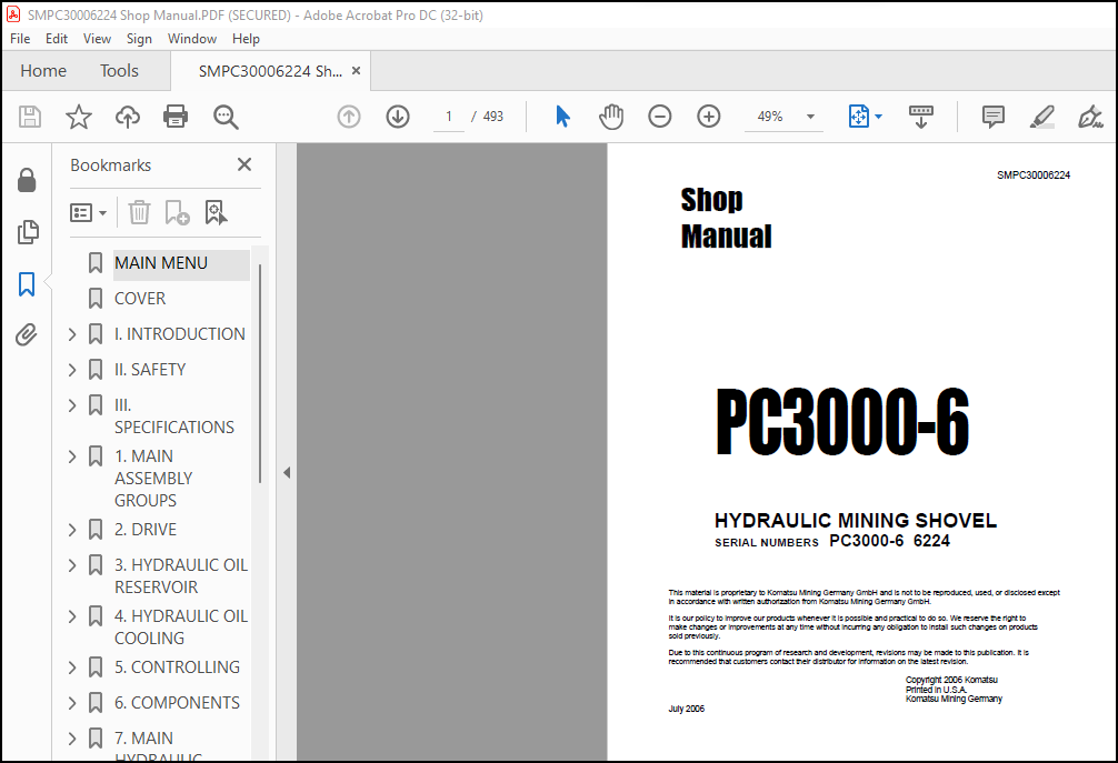
SERIAL NUMBERS PC3000-6 6224
The Komatsu PC3000-6 Hydraulic Mining Shovel Shop Manual SMPC30006224 is a comprehensive guide that provides detailed information on the maintenance and repair of the Komatsu PC3000-6 Hydraulic Mining Shovel. This manual is designed to be used by maintenance personnel who are responsible for the safe and efficient maintenance and repair of the machine.
- The manual is divided into several sections, each providing valuable information on specific aspects of the machine’s maintenance and repair. The first section provides an overview of the machine’s features and specifications, including its engine, hydraulic system, electrical system, and structural components. This section also includes information on the machine’s safety features and important safety guidelines for maintenance and repair personnel.
- The second section of the manual provides detailed information on the disassembly and assembly of the machine. This includes instructions for disassembling and assembling the machine’s various components and systems, including the engine, hydraulic system, electrical system, and structural components. This section also includes information on how to align and adjust the various components and systems to ensure proper operation and performance.
- The third section of the manual provides information on the testing and adjustment of the machine’s components and systems. This includes procedures for testing and adjusting the engine, hydraulic system, electrical system, and other components of the machine to ensure proper operation and performance.
- The fourth section of the manual provides information on troubleshooting and repairing the machine. This includes procedures for diagnosing and repairing common problems, as well as information on how to replace worn or damaged parts. This section also includes information on how to perform welding and other fabrication work on the machine’s structural components.
- The manual also includes several appendices that provide additional information on topics such as specifications and dimensions, hydraulic system diagrams, and electrical system diagrams. These appendices can be especially useful for maintenance personnel who are responsible for maintaining and repairing the machine.
- Overall, the Komatsu PC3000-6 Hydraulic Mining Shovel Shop Manual SMPC30006224 is an essential resource for anyone involved in the maintenance and repair of this machine. Its detailed information and step-by-step procedures can help ensure the safe and efficient maintenance and repair of the machine, and its troubleshooting procedures can help minimize downtime and increase productivity.
TABLE OF CONTENTS:
Komatsu PC3000-6 Hydraulic Mining Shovel Shop Manual SMPC30006224 – PDF DOWNLOAD
MAIN MENU………………………………………………………………………………….. 0
COVER……………………………………………………………………………………… 1
I. INTRODUCTION…………………………………………………………………………….. 3
I.I CONTENTS OF BINDER…………………………………………………………………… 4
I.II FOREWARD…………………………………………………………………………… 5
I.III EXPLANATION OF ABBREVATIONS…………………………………………………………. 7
I.IV TABLE OF CONTENTS…………………………………………………………………… 8
II. SAFETY…………………………………………………………………………………. 15
II.I SAFETY INSTRUCTIONS…………………………………………………………………. 16
II.II GENERAL PRECAUTIONS………………………………………………………………… 17
II.III PREPARATIONS FOR WORK……………………………………………………………… 18
II.IV PRECAUTIONS DURING WORK…………………………………………………………….. 19
III. SPECIFICATIONS…………………………………………………………………………. 21
III.I LIFTING GEARS……………………………………………………………………… 22
III.II STANDARD TIGHTENING TORQUE CHART……………………………………………………. 24
III.III CONVERSION TABLE…………………………………………………………………. 25
III.IV EXPLANATION OF ABBREVATIONS………………………………………………………… 31
III.V GENERAL SPECIFICATIONS……………………………………………………………… 32
1. MAIN ASSEMBLY GROUPS……………………………………………………………………… 33
1.1 General layout………………………………………………………………………. 34
1.2 Superstructure………………………………………………………………………. 36
1.3 Power House…………………………………………………………………………. 38
1.4 Hydraulic Oil Reservoir………………………………………………………………. 40
1.5 Hydraulic Oil Cooler…………………………………………………………………. 42
1.6 Fuel tank (Fuel reservoir)……………………………………………………………. 44
1.7 Counter weight………………………………………………………………………. 46
1.8 Cab support…………………………………………………………………………. 48
1.9 Operators cab……………………………………………………………………….. 50
1.10 Control blocks……………………………………………………………………… 52
1.11 Swing gears………………………………………………………………………… 54
1.12 Under carriage……………………………………………………………………… 56
2. DRIVE…………………………………………………………………………………… 59
2.1 Prime drive assembly…………………………………………………………………. 60
2.2 Engine and gearbox mount……………………………………………………………… 62
2.3 Torque supports……………………………………………………………………… 65
2.4 Radiator fan Drive Assy………………………………………………………………. 66
2.5 Pump distributor gearbox (PTO)………………………………………………………… 68
2.5.1 Spline shaft housing……………………………………………………………. 70
2.5.2 PTO lubrication and cooling……………………………………………………… 72
2.5.3 PTO valve adjustments…………………………………………………………… 74
2.6 Coupling……………………………………………………………………………. 78
2.7 Air Filter………………………………………………………………………….. 80
3. HYDRAULIC OIL RESERVOIR…………………………………………………………………… 83
3.1 Hydraulic oil reservoir………………………………………………………………. 84
3.2 Return and leak oil filter……………………………………………………………. 88
3.3 Breather Filter……………………………………………………………………… 92
3.4 Location of electrical components……………………………………………………… 94
4. HYDRAULIC OIL COOLING…………………………………………………………………….. 97
4.1 General…………………………………………………………………………….. 98
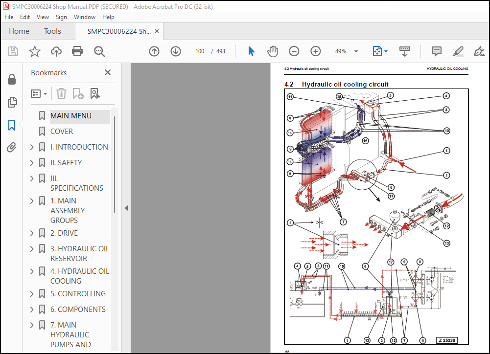
4.2 Hydraulic oil cooling circuit………………………………………………………….100
4.3 Back pressure valve adjustment…………………………………………………………104
4.4 Fan drive……………………………………………………………………………106
4.4.1 Fan pump……………………………………………………………………….108
4.4.2 Pressure relieve valve…………………………………………………………..109
4.4.3 Temperature relay……………………………………………………………….111
4.5 Cooler fan drive adjustment……………………………………………………………112
5. CONTROLLING………………………………………………………………………………115
5.1 Pilot pressure supply and adjustment……………………………………………………116
5.1.1 Pilot control arrangement………………………………………………………..119
5.1.2 Pilot pressure adjustment………………………………………………………..121
5.1.3 Check of Control Pressure………………………………………………………..123
5.2 Slew brakes………………………………………………………………………….125
5.3 Travel parking brake………………………………………………………………….128
5.4 Check of the pilot control logic……………………………………………………….130
5.4.1 Check sheet BHA Page 1…………………………………………………………..132
5.4.2 Check sheet FSA Page 1…………………………………………………………..145
6. COMPONENTS……………………………………………………………………………….155
6.1 Main control block and valve arrangement………………………………………………..156
6.1.1 FSA arrangement…………………………………………………………………158
6.1.2 BHA arrangement…………………………………………………………………162
6.2 Distributor manifold………………………………………………………………….166
6.2.1 Front shovel attachment FSA………………………………………………………166
6.2.2 Back hoe attachment BHA………………………………………………………….168
6.2.3 SRV with throttle check valve…………………………………………………….170
6.2.4 Anti cavitation valve (check valve)……………………………………………….172
6.3 Main control block……………………………………………………………………174
6.3.1 Load holding valve………………………………………………………………182
6.3.2 High pressure filter auxiliary filter……………………………………………..184
6.3.3 High pressure filter auxiliary filter……………………………………………..186
6.3.4 High pressure filter auxiliary filter……………………………………………..188
6.4 Compact valve blocks………………………………………………………………….190
6.5 Compact valve blocks………………………………………………………………….192
6.6 Auxiliary gear pumps………………………………………………………………….194
6.7 Hydraulic cylinder……………………………………………………………………196
6.8 Swing ring…………………………………………………………………………..198
7. MAIN HYDRAULIC PUMPS AND PUMP REGULATION…………………………………………………….201
7.1 General……………………………………………………………………………..202
7.1.1 Pump location…………………………………………………………………..204
7.2 Main pump operating principles…………………………………………………………206
7.2.1 Main pump function………………………………………………………………211
7.3 Main pump checks and adjustments……………………………………………………….214
7.3.1 Peak point diesel engine test…………………………………………………….214
7.3.2 Pressure transducer test…………………………………………………………216
7.3.3 Cut off function………………………………………………………………..217
7.3.4 Pump regulation…………………………………………………………………219
7.3.5 Swing pump volume reduction………………………………………………………220
7.4 Electronic pump regulation…………………………………………………………….221
7.4.1 Pump Controller CR700……………………………………………………………223
7.4.2 Multi Monitor…………………………………………………………………..225
7.4.3 Multimonitor software instruction…………………………………………………227
7.4.4 Table of fault messages and adjustments……………………………………………234
7.5 Trouble shooting pump and pump regulation……………………………………………….243
8. OPERATING HYDRAULIC……………………………………………………………………….247
8.1 General layout……………………………………………………………………….248
8.2 Floating function of boom and stick only FSA…………………………………………….252
8.3 Check and Adjustments for MRV’s and SRV’s……………………………………………….254
8.3.1 Check and Adjustments for MRV…………………………………………………….256
8.3.2 Check and Adjustment for SRV’s……………………………………………………258
8.3.3 Check and adjustment of the throttle check valves…………………………………..266
8.4 Hydraulic for the swing circuit………………………………………………………..268
8.4.1 Hydraulic for the swing circuit…………………………………………………..272
8.4.2 Slew gear box L & S……………………………………………………………..276
8.4.3 Slew parking brake………………………………………………………………280
8.4.4 Slew service brake valve…………………………………………………………284
8.4.5 Checks and adjustment of the slew pressure valve……………………………………289
8.5 Travel circuit……………………………………………………………………….292
8.5.1 Rotary joint……………………………………………………………………294
8.5.2 Travel motor A2FMt………………………………………………………………296
8.5.3 Travel gear…………………………………………………………………….298
8.5.4 Travel parking brake…………………………………………………………….300
8.5.5 Travel control function………………………………………………………….302
9. TRACK TENSION SYSTEM………………………………………………………………………307
9.1 General layout……………………………………………………………………….308
9.2 Track tensioning function……………………………………………………………..310
9.2.1 Cushioning……………………………………………………………………..312
9.2.2 Pressure Increasing valve PIV…………………………………………………….314
9.3 Truck tensioning adjustment……………………………………………………………318
9.3.1 Truck tensioning function check…………………………………………………..320
10. ACCESS LADDER HYDRAULICALLY OPERATED……………………………………………………….323
10.1 Access ladder……………………………………………………………………….324
10.2 Access ladder functional description…………………………………………………..326
11. CENTRAL REFILLING SYSTEM………………………………………………………………….331
11.0.1 Functional description……………………………………………………………..332
12. HINTS FOR READING THE HYDRAULIC CIRCUIT DIAGRAM……………………………………………..337
12.1 General…………………………………………………………………………….338
12.2 Symbolic……………………………………………………………………………340
12.2.1 Lines, unions………………………………………………………………….341
12.2.2 Components, valves……………………………………………………………..343
12.2.3 Sensors……………………………………………………………………….343
12.2.4 Valves, valve components………………………………………………………..344
12.2.5 Pump, motor, cylinder…………………………………………………………..348
Hydraulic Diagrams – 938 367 40……………………………………………………………352
Hydraulic Diagrams – 938 367 40 (1/3)…………………………………………………..352
Hydraulic Diagrams – 938 367 40 (2/3)…………………………………………………..353
Hydraulic Diagrams – 938 367 40 (3/3)…………………………………………………..354
13. HINTS FOR READING THE ELECTRIC CIRCUIT DIAGRAM………………………………………………356
13.1 Designation of electrical components…………………………………………………..358
13.2 Electric symbols…………………………………………………………………….359
13.3 Symbols…………………………………………………………………………….361
13.3.1 Drawing concept………………………………………………………………..363
13.3.2 Reading of the circuit diagram…………………………………………………..369
Electrical Diagrams………………………………………………………………………373
Electrical Diagrams – 938 368 40 (1/54)…………………………………………………373
Electrical Diagrams – 938 368 40 (2/54)…………………………………………………374
Electrical Diagrams – 938 368 40 (3/54)…………………………………………………375
Electrical Diagrams – 938 368 40 (4/54)…………………………………………………376
Electrical Diagrams – 938 368 40 (5/54)…………………………………………………377
Electrical Diagrams – 938 368 40 (6/54)…………………………………………………378
Electrical Diagrams – 938 368 40 (7/54)…………………………………………………379
Electrical Diagrams – 938 368 40 (8/54)…………………………………………………380
Electrical Diagrams – 938 368 40 (9/54)…………………………………………………381
Electrical Diagrams – 938 368 40 (10/54)………………………………………………..382
Electrical Diagrams – 938 368 40 (11/54)………………………………………………..383
Electrical Diagrams – 938 368 40 (12/54)………………………………………………..384
Electrical Diagrams – 938 368 40 (13/54)………………………………………………..385
Electrical Diagrams – 938 368 40 (14/54)………………………………………………..386
Electrical Diagrams – 938 368 40 (15/54)………………………………………………..387
Electrical Diagrams – 938 368 40 (16/54)………………………………………………..388
Electrical Diagrams – 938 368 40 (17/54)………………………………………………..389
Electrical Diagrams – 938 368 40 (18/54)………………………………………………..390
Electrical Diagrams – 938 368 40 (19/54)………………………………………………..391
Electrical Diagrams – 938 368 40 (20/54)………………………………………………..392
Electrical Diagrams – 938 368 40 (21/54)………………………………………………..393
Electrical Diagrams – 938 368 40 (22/54)………………………………………………..394
Electrical Diagrams – 938 368 40 (23/54)………………………………………………..395
Electrical Diagrams – 938 368 40 (24/54)………………………………………………..396
Electrical Diagrams – 938 368 40 (25/54)………………………………………………..397
Electrical Diagrams – 938 368 40 (26/54)………………………………………………..398
Electrical Diagrams – 938 368 40 (27/54)………………………………………………..399
Electrical Diagrams – 938 368 40 (28/54)………………………………………………..400
Electrical Diagrams – 938 368 40 (29/54)………………………………………………..401
Electrical Diagrams – 938 368 40 (30/54)………………………………………………..402
Electrical Diagrams – 938 368 40 (31/54)………………………………………………..403
Electrical Diagrams – 938 368 40 (32/54)………………………………………………..404
Electrical Diagrams – 938 368 40 (33/54)………………………………………………..405
Electrical Diagrams – 938 368 40 (34/54)………………………………………………..406
Electrical Diagrams – 938 368 40 (35/54)………………………………………………..407
Electrical Diagrams – 938 368 40 (36/54)………………………………………………..408
Electrical Diagrams – 938 368 40 (37/54)………………………………………………..409
Electrical Diagrams – 938 368 40 (38/54)………………………………………………..410
Electrical Diagrams – 938 368 40 (39/54)………………………………………………..411
Electrical Diagrams – 938 368 40 (40/54)………………………………………………..412
Electrical Diagrams – 938 368 40 (41/54)………………………………………………..413
Electrical Diagrams – 938 368 40 (42/54)………………………………………………..414
Electrical Diagrams – 938 368 40 (43/54)………………………………………………..415
Electrical Diagrams – 938 368 40 (44/54)………………………………………………..416
Electrical Diagrams – 938 368 40 (45/54)………………………………………………..417
Electrical Diagrams – 938 368 40 (46/54)………………………………………………..418
Electrical Diagrams – 938 368 40 (47/54)………………………………………………..419
Electrical Diagrams – 938 368 40 (48/54)………………………………………………..420
Electrical Diagrams – 938 368 40 (49/54)………………………………………………..421
Electrical Diagrams – 938 368 40 (50/54)………………………………………………..422
Electrical Diagrams – 938 368 40 (51/54)………………………………………………..423
Electrical Diagrams – 938 368 40 (52/54)………………………………………………..424
Electrical Diagrams – 938 368 40 (53/54)………………………………………………..425
Electrical Diagrams – 938 368 40 (54/54)………………………………………………..426
14. ELECTRONIC TEXT MONITORING SYSTEM ETM………………………………………………………428
14.1 General Function…………………………………………………………………….429
15. AUTOMATIC LUBRICATION SYSTEM………………………………………………………………432
15.1 General Function…………………………………………………………………….433
15.2 Function of a lubrication cycle……………………………………………………….435
15.3 Lubrication pump drive……………………………………………………………….443
15.4 Lubrication pump…………………………………………………………………….445
15.4.1 Adjustments lubricating pump speed……………………………………………….447
15.4.2 Adjustments lubricating pump pressure…………………………………………….449
15.5 Lubricant Injector (metering valve)……………………………………………………451
15.5.1 Connection of one or more injectors………………………………………………453
15.5.2 Function lubrication injector (metering valve)…………………………………….455
15.6 End line pressure switch……………………………………………………………..459
15.7 Lubricant in line filter……………………………………………………………..461
15.8 Lubricant level sensor……………………………………………………………….463
15.8.1 Capacitive digital type for machines with ETM……………………………………..463
15.8.2 Capacitive analog type for machines with PLC………………………………………465
15.9 Lubrication system function and controlling…………………………………………….468
15.9.1 Central Lubrication System (CLS) function and controlling with ETM system (PC 3000)……469
15.9.2 Swing ring lubrication system (SLS) function and controlling with ETM system (PC3000)….473
15.10 Adjustment of the lubrication system with ETM………………………………………….479
15.11 Trouble shooting lubricating system…………………………………………………..481
15.11.1 Lubrication pump cylinder does not move………………………………………….482
15.11.2 Lubricant pressure built up very slowly or not at all……………………………..484
15.11.3 Insufficient lubricant supply to one or more attachment bearings……………………484
15.11.4 Insufficient lubricant at the swing ring gear…………………………………….486
More products