$43
Komatsu PC3000E-6 Hydraulic Mining Excavator Shop Manual – PDF DOWNLOAD
Komatsu PC3000E-6 Hydraulic Mining Excavator Shop Manual – PDF DOWNLOAD
FILE DETAILS:
Komatsu PC3000E-6 Hydraulic Mining Excavator Shop Manual – PDF DOWNLOAD
Language : English
Pages : 1785
Downloadable : Yes
File Type : PDF
Size: 48.1 MB
IMAGES PREVIEW OF THE MANUAL:

DESCRIPTION:
Komatsu PC3000E-6 Hydraulic Mining Excavator Shop Manual – PDF DOWNLOAD
Machine model Serial numbers
P0300056 06249 and up
46225 and up
- The Komatsu PC3000E-6 Hydraulic Mining Excavator Shop Manual is a digital document that can be downloaded in PDF format. This manual is a comprehensive guide that provides detailed information on the maintenance and repair of the Komatsu PC3000E-6 Hydraulic Mining Excavator.
- The manual is divided into several sections, each providing valuable information on specific aspects of the machine’s maintenance and repair. The first section provides an overview of the machine’s features and specifications, including its engine, hydraulic system, electrical system, and structural components. This section also includes information on the machine’s safety features and important safety guidelines for maintenance and repair personnel.
- The second section of the manual provides detailed information on the disassembly and assembly of the machine. This includes instructions for disassembling and assembling the machine’s various components and systems, including the engine, hydraulic system, electrical system, and structural components. This section also includes information on how to align and adjust the various components and systems to ensure proper operation and performance.
- The third section of the manual provides information on the testing and adjustment of the machine’s components and systems. This includes procedures for testing and adjusting the engine, hydraulic system, electrical system, and other components of the machine to ensure proper operation and performance.
- The fourth section of the manual provides information on troubleshooting and repairing the machine. This includes procedures for diagnosing and repairing common problems, as well as information on how to replace worn or damaged parts. This section also includes information on how to perform welding and other fabrication work on the machine’s structural components.
- The manual also includes several appendices that provide additional information on topics such as specifications and dimensions, hydraulic system diagrams, and electrical system diagrams. These appendices can be especially useful for maintenance personnel who are responsible for maintaining and repairing the machine.
- Overall, the Komatsu PC3000E-6 Hydraulic Mining Excavator Shop Manual PDF download is a convenient and essential resource for anyone involved in the maintenance and repair of this machine. Its detailed information and step-by-step procedures can help ensure the safe and efficient maintenance and repair of the machine, and its troubleshooting procedures can help minimize downtime and increase productivity.
TABLE OF CONTENTS:
Komatsu PC3000E-6 Hydraulic Mining Excavator Shop Manual – PDF DOWNLOAD
COVER ………………………………………………………………………………………………….. 1
00 FOREWORD …………………………………………………………………………………………….. 3
1 Foreword…………………………………………………………………………………………… 5
1.1 Before reading this manual……………………………………………………………………… 6
1.2 Contents of this binder………………………………………………………………………… 7
1.2.1 Contacting the Service……………………………………………………………………. 7
1.2.2 Guarantee……………………………………………………………………………….. 7
1.3 Division of the binder ………………………………………………………………………… 8
2 SAFETY…………………………………………………………………………………………….. 9
2.1 SAFETY INFORMATION…………………………………………………………………………….. 11
2.2 OVERVIEW……………………………………………………………………………………… 12
2.2.1 NORMAL OPERATIONS………………………………………………………………………… 12
2.2.2 REGULAR MAINTENANCE………………………………………………………………………. 12
2.2.3 TROUBLESHOOTING, ADJUSTMENTS AND REPAIR…………………………………………………….. 12
2.2.4 ADDITIONAL SAFETY PRECAUTIONS FOR ASSEMBLING, DISASSEMBLING AND TRANSPORTATION OF THE EXCAVATOR…… 12
2.3 SOUND PRESSURE LEVEL IN THE OPERATOR’S CAB……………………………………………………….. 13
2.4 GENERAL PRECAUTIONS COMMON TO OPERATION ON THE EXCAVATOR…………………………………………… 14
2.4.1 UNDERSTANDING THE MACHINE…………………………………………………………………. 14
2.4.2 PRECAUTIONS BEFORE STARTING OPERATION ON THE EXCAVATOR……………………………………….. 14
2.4.2.1 ENSURING SAFE OPERATION……………………………………………………………… 14
2.4.3 PREPARATIONS FOR SAFE OPERATION……………………………………………………………. 14
2.4.3.1 PRECAUTIONS REGARDING SAFETY RELATED EQUIPMENT…………………………………………. 14
2.4.3.2 INSPECTING THE MACHINE………………………………………………………………. 14
2.4.3.3 WEAR WELL FITTING CLOTHES AND PROTECTIVE EQUIPMENT……………………………………… 15
2.4.3.4 KEEP MACHINE CLEAN………………………………………………………………….. 15
2.4.3.5 PRECAUTIONS INSIDE OPERATOR’S COMPARTMENT……………………………………………… 15
2.4.3.6 PROVIDE FIRE EXTINGUISHER AND FIRST AID KIT……………………………………………. 16
2.4.3.7 IF A PROBLEM IS FOUND……………………………………………………………….. 16
2.4.4 FIRE PREVENTION………………………………………………………………………….. 16
2.4.4.1 PRECAUTIONS TO PREVENT FIRE………………………………………………………….. 16
2.4.4.2 ACTION IF FIRE OCCURS……………………………………………………………….. 17
2.4.4.3 EMERGENCY EXIT FROM OPERATOR’S CAB……………………………………………………. 18
2.4.5 PRECAUTIONS WHEN GETTING ON OR OFF THE MACHINE………………………………………………. 18
2.4.5.1 USE HANDRAILS AND STEPS WHEN GETTING ON OR OFF THE MACHINE………………………………. 18
2.4.5.2 NO JUMPING ON OR OFF THE MACHINE……………………………………………………… 18
2.4.5.3 NO PEOPLE ON THE ATTACHMENT………………………………………………………….. 18
2.4.5.4 WORKING IN HIGH PLACES………………………………………………………………. 18
2.4.5.5 LEAVING OPERATOR’S SEAT WITH LOCK…………………………………………………….. 19
2.4.5.6 LEAVING THE MACHINE…………………………………………………………………. 19
2.4.6 BURN PREVENTION………………………………………………………………………….. 20
2.4.6.1 Hot coolant………………………………………………………………………… 20
2.4.6.2 Hot oil……………………………………………………………………………. 20
2.4.7 PRECAUTIONS WHEN CLEANING CAB GLASS………………………………………………………… 20
2.4.8 PRECAUTIONS RELATED TO PROTECTIVE STRUCTURES………………………………………………… 21
2.4.8.1 UNAUTHORIZED MODIFICATION……………………………………………………………. 21
2.4.8.2 PRECAUTIONS RELATED TO ATTACHMENTS AND OPTIONS…………………………………………. 21
2.4.9 PRECAUTIONS AT JOBSITE……………………………………………………………………. 22
2.4.9.1 VISIBILITY FROM OPERATOR’S SEAT………………………………………………………. 23
2.4.9.2 CAMERA SYSTEM WITH MONITORS………………………………………………………….. 23
2.4.9.3 ENSURE GOOD VISIBILITY………………………………………………………………. 23
2.4.9.4 CHECKING SIGNS AND SIGNALMAN’S SIGNALS………………………………………………… 23
2.4.9.5 INVESTIGATE AND CONFIRM JOBSITE CONDITIONS…………………………………………….. 24
2.4.9.6 DO NOT GO CLOSE TO HIGH VOLTAGE CABLES………………………………………………… 24
2.4.9.7 WORKING ON LOOSE GROUND……………………………………………………………… 25
2.4.9.8 GAS, DUST, STEAM AND SMOKE…………………………………………………………… 25
2.4.9.9 VENTILATION OF ENCLOSED AREAS………………………………………………………… 26
2.4.10 STARTING ENGINE…………………………………………………………………………. 27
2.4.10.1 WARNING TAG……………………………………………………………………….. 27
2.4.10.2 CHECKS BEFORE STARTING ENGINE……………………………………………………….. 27
2.4.10.3 PRECAUTION WHEN STARTING ENGINE……………………………………………………… 27
2.4.10.4 PRECAUTION IN COLD AREAS……………………………………………………………. 28
2.4.11 OPERATION………………………………………………………………………………. 28
2.4.11.1 CHECKS BEFORE OPERATION…………………………………………………………….. 28
2.4.11.2 PRECAUTIONS WHEN TRAVELLING IN FORWARD OR REVERSE……………………………………… 29
2.4.11.3 PRECAUTIONS WHEN travelling…………………………………………………………. 30
2.4.11.4 TRAVELLING ON SLOPES……………………………………………………………….. 31
2.4.11.5 OPERATIONS ON SLOPES……………………………………………………………….. 32
2.4.11.6 PROHIBITED OPERATIONS………………………………………………………………. 32
2.4.11.7 TRAVELLING ON FROZEN OR SNOW COVERED SURFACES…………………………………………. 33
2.4.11.8 PARKING THE MACHINE………………………………………………………………… 33
2.4.11.9 TRANSPORTATION…………………………………………………………………….. 33
2.5 PRECAUTION FOR MAINTENANCE……………………………………………………………………… 34
2.5.1 GENERAL PRECAUTIONS………………………………………………………………………. 34
2.5.1.1 SELECTION AND QUALIFICATION OF PERSONNEL – BASIC RESPONSIBILITIES………………………… 35
2.5.1.2 STOP ENGINE FOR MAINTENANCE………………………………………………………….. 36
2.5.1.3 WARNING TAG………………………………………………………………………… 37
2.5.1.4 KEEP WORKPLACE CLEAN AND TIDY………………………………………………………… 38
2.5.1.5 APPOINT LEADER WHEN WORKING WITH OTHERS……………………………………………….. 38
2.5.1.6 TWO WORKERS FOR MAINTENANCE WHEN THE MACHINE IS RUNNING…………………………………. 39
2.5.1.7 INSTALLING, REMOVING OR STORING ATTACHMENTS……………………………………………. 39
2.5.1.8 PRECAUTIONS WHEN WORKING UNDER THE MACHINE OR EQUIPMENT…………………………………. 40
2.5.1.9 NOISE……………………………………………………………………………… 40
2.5.1.10 WHEN USING A HAMMER………………………………………………………………… 40
2.5.1.11 PROPER TOOLS………………………………………………………………………. 41
2.5.1.12 ACCUMULATOR……………………………………………………………………….. 41
2.5.1.13 PERSONNEL…………………………………………………………………………. 41
2.5.2 PRECAUTIONS FOR INSPECTION AND MAINTENANCE………………………………………………….. 42
2.5.2.1 PRECAUTION WHEN WELDING……………………………………………………………… 42
2.5.2.2 BATTERY HANDLING……………………………………………………………………. 42
2.5.3 PRECAUTIONS WITH HIGH PRESSURE Fluid……………………………………………………….. 43
2.5.3.1 PRECAUTIONS WITH HIGH FUEL PRESSURE…………………………………………………… 43
2.5.3.2 HANDLING HIGH PRESSURES HOSES OR PIPES………………………………………………… 44
2.5.3.3 REPLACEMENT OF HOSE LINES……………………………………………………………. 44
2.5.3.4 INSPECTION OF HOSE LINES…………………………………………………………….. 44
2.5.3.5 PERIODIC REPLACEMENT OF SAFETY CRITICAL PARTS………………………………………….. 45
2.5.3.6 PRECAUTIONS FOR HIGH VOLTAGE…………………………………………………………. 45
2.5.3.7 AIR CONDITIONING MAINTENANCE…………………………………………………………. 45
2.5.3.8 COMPRESSED AIR……………………………………………………………………… 46
2.5.3.9 WASTE MATERIALS…………………………………………………………………….. 46
2.6 ADDITIONAL SAFETY INFORMATION FOR TROUBLESHOOTING AND ADJUSTMENTS…………………………………… 47
2.6.1 INSPECTION OF THE HYDRAULIC SYSTEM…………………………………………………………. 47
2.6.2 TWO WORKERS ONLY WHEN THE MACHINE IS RUNNING DURING ADJUSTMENTS……………………………….. 47
2.6.3 AREAS OF POTENTIAL DANGER AROUND THE EXCAVATOR………………………………………………. 47
2.7 SPECIAL SAFETY EQUIPMENT……………………………………………………………………….. 48
2.7.1 FRONT GUARD PROTECTIVE STRUCTUR ’FOPS’ FOR OPERATOR’S CAB…………………………………….. 49
2.7.2 OBJECT HANDLING………………………………………………………………………….. 49
2.7.3 LIGHTING………………………………………………………………………………… 49
2.7.4 WARNING BEACON…………………………………………………………………………… 49
2.7.5 SAFETY HARNESS IN CONFORMITY WITH EN 361 (EUROPEAN STANDARD)………………………………….. 49
2.7.5.1 SAFETY HARNESS IN CONFORMITY WITH EN 361 (EUROPEAN STANDARD)…………………………….. 49
2.7.5.2 INSTRUCTIONS FOR USE………………………………………………………………… 51
2.7.5.3 PRIOR TO USING THE HARNESS (1), THE WEARER SHALL……………………………………….. 53
2.7.5.4 RECOMMENDATIONS FOR USE OF THE HOLDING HOOKS AND HOLD-BACK HOOKS OF THE SAFETY HARNESS (1),…. 53
2.7.5.5 INSTRUCTIONS FOR USE………………………………………………………………… 55
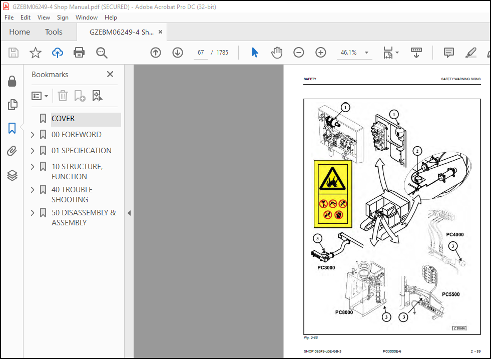
2.8 SAFETY WARNING SIGNS…………………………………………………………………………… 56
2.8.1 LOCATION AND DESCRIPTION OF THE SIGNS………………………………………………………. 57
01 SPECIFICATION ………………………………………………………………………………………… 71
PC3000………………………………………………………………………………………………. 73
10 STRUCTURE, FUNCTION …………………………………………………………………………………… 81
I. INTRODUCTION……………………………………………………………………………………… 91
II. SAFETY…………………………………………………………………………………………… 97
III. SPECIFICATIONS…………………………………………………………………………………… 103
1. MAIN ASSEMBLY GROUPS……………………………………………………………………………….. 121
1.1 General layout………………………………………………………………………………… 122
1.2 Superstructure………………………………………………………………………………… 124
1.3 Power House…………………………………………………………………………………… 126
1.4 Hydraulic Oil Reservoir………………………………………………………………………… 128
1.5 Hydraulic Oil Cooler…………………………………………………………………………… 130
1.6 High voltage switch cabinet…………………………………………………………………….. 132
1.7 Counter weight………………………………………………………………………………… 134
1.7.1 Safety instruction of counterweight handling………………………………………………… 137
1.8 Cab support…………………………………………………………………………………… 138
1.9 Operators cab…………………………………………………………………………………. 140
1.10 Control blocks……………………………………………………………………………….. 142
1.11 Swing machinery………………………………………………………………………………. 144
1.12 Undecarriage…………………………………………………………………………………. 146
1.13 Slip ring unit……………………………………………………………………………….. 148
2. DRIVE…………………………………………………………………………………………….. 151
2.1 Electric drive – Safety and operation instruction documents………………………………………… 152
2.2 Prime drive assembly…………………………………………………………………………… 154
2.3 Electric motor………………………………………………………………………………… 156
2.3.1 Motor type plate…………………………………………………………………………. 156
2.3.2 Type plate for the motor bearings………………………………………………………….. 157
2.3.3 Motor bearings & grease equipment………………………………………………………….. 158
2.3.4 Monitoring of the motor temperatures……………………………………………………….. 160
2.3.5 Checking of the bearing condition………………………………………………………….. 162
2.3.6 Capacitor assembly……………………………………………………………………….. 164
2.4 Initial Start-up procedure……………………………………………………………………… 166
2.4.1 Main supply cable………………………………………………………………………… 167
2.4.2 Motor protection relay (SPAM 150 C)………………………………………………………… 168
2.4.3 Motor alignment………………………………………………………………………….. 172
2.4.4 Motor rotation direction………………………………………………………………….. 174
2.4.5 Starting & Re-starting the electric motor…………………………………………………… 174
2.4.6 Supervision during the first motor running period……………………………………………. 175
2.5 Flexible coupling……………………………………………………………………………… 176
2.5.1 Check motor rotation direction…………………………………………………………….. 179
2.5.2 Coupling handling………………………………………………………………………… 179
2.5.3 Coupling inspection………………………………………………………………………. 180
2.5.4 Coupling replacement……………………………………………………………………… 181
2.6 Pump distributor gearbox (PTO)………………………………………………………………….. 182
2.6.1 Spline shaft housing……………………………………………………………………… 184
2.6.2 PTO lubrication and cooling……………………………………………………………….. 186
2.6.3 PTO valve adjustments…………………………………………………………………….. 188
2.6.4 Temperature relay………………………………………………………………………… 192
3. HYDRAULIC OIL RESERVOIR…………………………………………………………………………….. 195
3.1 Hydraulic oil reservoir………………………………………………………………………… 196
3.2 Return and leak oil filter……………………………………………………………………… 200
3.3 Breather Filter……………………………………………………………………………….. 204
3.4 Location of electrical components……………………………………………………………….. 206
3.5 Transfer pump, hydraulic service………………………………………………………………… 208
3.5.1 Evacuation of the suction oil reservoir…………………………………………………….. 211
3.5.2 Evacuation of the return oil collector pipes and cooler circuit……………………………….. 213
4. HYDRAULIC OIL COOLING………………………………………………………………………………. 215
4.1 General………………………………………………………………………………………. 216
4.2 Hydraulic oil cooling circuit…………………………………………………………………… 218
4.3 Back pressure valve adjustment………………………………………………………………….. 222
4.4 Fan drive…………………………………………………………………………………….. 224
4.4.1 Fan pump………………………………………………………………………………… 226
4.4.2 Pressure relieve valve……………………………………………………………………. 228
4.4.3 Temperature relay………………………………………………………………………… 230
4.5 Cooler fan drive adjustment…………………………………………………………………….. 232
5. CONTROLLING……………………………………………………………………………………….. 235
5.1 General Layout………………………………………………………………………………… 236
5.1.1 Pilot control……………………………………………………………………………. 238
5.2 Control and filter panel……………………………………………………………………….. 240
5.3 Pilot oil gear pump……………………………………………………………………………. 244
5.4 Pilot pressure supply and adjustment…………………………………………………………….. 246
5.4.1 Pilot pressure adjustment…………………………………………………………………. 248
5.4.2 Check of pilot pressure…………………………………………………………………… 250
6. COMPONENTS………………………………………………………………………………………… 253
6.1 Main control block and valve arrangement…………………………………………………………. 254
6.1.1 FSA arrangement………………………………………………………………………….. 256
6.1.2 BHA arrangement………………………………………………………………………….. 260
6.2 Distributor manifold…………………………………………………………………………… 264
6.2.1 Front shovel attachment FSA……………………………………………………………….. 264
6.2.2 Back hoe attachment BHA…………………………………………………………………… 266
6.2.3 SRV with throttle check valve……………………………………………………………… 268
6.2.4 Anti cavitation valve (check valve)………………………………………………………… 270
6.3 SINGLE CONTROL BLOCKS (FLOATING) FOR STICK AND BOOM (FSA)………………………………………….. 272
6.4 Main control block…………………………………………………………………………….. 274
6.4.1 Load holding valve……………………………………………………………………….. 282
6.4.2 High pressure filter……………………………………………………………………… 284
6.4.3 Pressure relieve valves and anti-cavitation valve……………………………………………. 286
6.4.4 Pressure relieve valves and anti-cavitation valve……………………………………………. 288
6.5 4/2 Directional valves…………………………………………………………………………. 290
6.6 Travel brake valve…………………………………………………………………………….. 292
6.7 Pressure double stage valve…………………………………………………………………….. 294
6.8 Hydraulic cylinder…………………………………………………………………………….. 296
6.9 Swing ring……………………………………………………………………………………. 300
7. MAIN HYDRAULIC PUMPS AND PUMP REGULATION……………………………………………………………… 303
7.1 General………………………………………………………………………………………. 304
7.1.1 Pump location……………………………………………………………………………. 306
7.2 Main pump operating principles………………………………………………………………….. 308
7.2.1 Main pump operating principals…………………………………………………………….. 308
7.2.2 Main pump function……………………………………………………………………….. 313
7.3 Main pump checks and adjustments………………………………………………………………… 316
7.3.1 Power check……………………………………………………………………………… 316
7.3.2 Cut off function…………………………………………………………………………. 319
7.3.3 Swing pump volume reduction……………………………………………………………….. 321
7.4 Electronic pump regulation……………………………………………………………………… 322
7.4.1 General…………………………………………………………………………………. 322
7.4.2 Signal rectifier module (ESR)……………………………………………………………… 324
7.5 Pump controller CR700………………………………………………………………………….. 328
7.6 Multi Monitor…………………………………………………………………………………. 330
7.7 Multimonitor software instruction……………………………………………………………….. 332
7.7.1 Multimonitor main control…………………………………………………………………. 332
7.7.2 Service Menu screen………………………………………………………………………. 332
7.7.3 Monitoring (menu item 01)…………………………………………………………………. 333
7.7.4 Abnormality Record (menu item 02)………………………………………………………….. 334
7.7.5 Default (menu item 03)……………………………………………………………………. 337
7.7.6 Adjustment (menu item 04)…………………………………………………………………. 338
7.7.7 Display Setup (menu item 05)………………………………………………………………. 340
7.7.8 Table of fault messages and adjustments…………………………………………………….. 341
7.8 Trouble shooting pump and pump regulation………………………………………………………… 350
8. OPERATING HYDRAULIC………………………………………………………………………………… 351
8.1 General layout………………………………………………………………………………… 352
8.2 Floating function of boom and stick (only FSA)……………………………………………………. 354
8.3 Check and Adjustments for MRV and SRV……………………………………………………………. 356
8.3.1 Check and Adjustments for MRV……………………………………………………………… 357
8.3.2 Check and Adjustment for SRV………………………………………………………………. 360
8.3.3 .Check and Adjustment for SRV’s of FSA attachment……………………………………………. 364
8.3.4 Check and Adjustment for SRV’s of BHA attachment…………………………………………….. 366
8.3.5 Check and adjustment of the throttle check valves……………………………………………. 368
8.4 Hydraulic for the swing circuit…………………………………………………………………. 370
8.4.1 Swing motor……………………………………………………………………………… 372
8.4.2 Swing gearbox (L&S)………………………………………………………………………. 376
8.4.3 Swing gearbox (Siebenhaar)………………………………………………………………… 378
8.4.4 Swing parking brake (L&S)…………………………………………………………………. 382
8.4.5 Swing parking brake (Siebenhaar)…………………………………………………………… 384
8.4.6 Swing service brake valve…………………………………………………………………. 386
8.4.7 Checks and adjustments for the swing circuit………………………………………………… 390
8.4.8 Function check of swing parking brake………………………………………………………. 394
8.5 Hydraulics for the travel circuit……………………………………………………………….. 396
8.5.1 Travel circuit…………………………………………………………………………… 396
8.5.2 Rotary joint…………………………………………………………………………….. 398
8.5.3 Travel motor A2FMt……………………………………………………………………….. 402
8.5.4 Travel gearbox…………………………………………………………………………… 406
8.5.5 Travel parking brake……………………………………………………………………… 408
8.5.6 Check and Adjustment for the travel circuit…………………………………………………. 410
8.5.7 Function check for the travel parking brake…………………………………………………. 412
9. TRACK TENSION SYSTEM……………………………………………………………………………….. 415
9.1 General layout………………………………………………………………………………… 416
9.2 Functional description…………………………………………………………………………. 418
9.2.1 Cushioning………………………………………………………………………………. 420
9.2.2 Double stage valve……………………………………………………………………….. 422
9.3 Checks and adjustments…………………………………………………………………………. 426
10. ACCESS LADDER HYDRAULICALLY OPERATED………………………………………………………………… 429
10.1 Access ladder………………………………………………………………………………… 430
10.2 Access ladder functional description……………………………………………………………. 432
11. HINTS FOR READING THE HYDRAULIC CIRCUIT DIAGRAM………………………………………………………. 437
11.1 General……………………………………………………………………………………… 438
11.2 Symbolic…………………………………………………………………………………….. 440
11.2.1 Lines, unions…………………………………………………………………………… 441
11.2.2 Components, valves………………………………………………………………………. 443
11.2.3 Sensors………………………………………………………………………………… 443
11.2.4 Valves, valve components…………………………………………………………………. 444
11.2.5 Pump, motor, cylinder……………………………………………………………………. 448
12. HINTS FOR READING THE ELECTRIC CIRCUIT DIAGRAM……………………………………………………….. 453
12.1 Designation of electrical components……………………………………………………………. 455
12.2 Electric symbols……………………………………………………………………………… 456
12.3 Symbols……………………………………………………………………………………… 458
12.3.1 Drawing concept…………………………………………………………………………. 460
12.3.2 Reading of the circuit diagram……………………………………………………………. 466
13. ELECTRONIC TEXT MONITORING SYSTEM ETM……………………………………………………………….. 471
13.1 Introduction…………………………………………………………………………………. 472
14. AUTOMATIC LUBRICATION SYSTEM……………………………………………………………………….. 475
14.1 General Function……………………………………………………………………………… 476
14.1.1 Central lubrication system (CLS)………………………………………………………….. 478
14.1.2 Swing ring lubrication system (SLS)……………………………………………………….. 480
14.2 Lubrication cycle…………………………………………………………………………….. 482
14.3 Hydraulically driven lubrication pump…………………………………………………………… 490
14.3.1 Function of the pump…………………………………………………………………….. 492
14.3.2 Adjustment of lubricating pump speed & working pressure……………………………………… 494
14.4 Lubricant Injector (metering valve)…………………………………………………………….. 498
14.4.1 Tightening torques for fittings at grease injectors…………………………………………. 499
14.4.2 Injector type description………………………………………………………………… 501
14.4.3 Adjustment of the lubricant output………………………………………………………… 501
14.4.4 Connection of one or more injectors……………………………………………………….. 502
14.4.5 Operation principle of lubricant injectors…………………………………………………. 504
14.5 Vent valve…………………………………………………………………………………… 508
14.6 End-line pressure switch………………………………………………………………………. 510
14.6.1 End-line switch adjustment……………………………………………………………….. 512
14.7 Lubricant in-line filter………………………………………………………………………. 514
14.8 Adjustment of the lubrication intervals…………………………………………………………. 516
14.8.1 Timing adjustment……………………………………………………………………….. 517
14.9 Commissioning………………………………………………………………………………… 518
14.9.1 Commissioning of the CLS lubrication system………………………………………………… 518
14.9.2 Fine adjustment…………………………………………………………………………. 519
14.9.3 Commissioning of the SLS lubrication system………………………………………………… 520
40 TROUBLE SHOOTING ……………………………………………………………………………………… 523
TABLE OF CONTENTS ……………………………………………………………………………………. 525
INTRODUCTION…………………………………………………………………………………………. 529
Introduction & general information for troubleshooting………………………………………………… 530
Description of this troubleshooting manual……………………………………………………….. 530
Precautions when carrying out any operation………………………………………………………. 533
Fundamental requirements for troubleshooting……………………………………………………… 534
Points to remember when troubleshooting………………………………………………………….. 535
Sequence of events in troubleshooting……………………………………………………………. 538
Checks before troubleshooting…………………………………………………………………… 539
Handling of electric equipment and hydraulic components……………………………………………. 540
General working procedures……………………………………………………………………… 544
Information on the ETM Versions and the Electronic Pump Controller CR700…………………………….. 548
service level password…………………………………………………………………………. 550
ELECTRICAL PARTS……………………………………………………………………………………… 553
Mounting locations of electrical parts, connector types and electrical standard values……………………. 554
Component locations……………………………………………………………………………. 554
Location of electrical parts Capacitor / electric motor……………………………………………. 556
Location of electrical parts on PTO, Suction Oil Reservoir and Central Control and Filter Panel………… 558
Location of electrical parts on Pilot Control Frame……………………………………………….. 560
Location of electrical parts on Main Hydraulic Oil Reservoir……………………………………….. 562
Location of electrical parts on Switch Board X2 in Cab Base………………………………………… 564
Location of electrical parts of the hydraulically operated Access Ladder…………………………….. 566
Location of electrical parts of the automatic Lubrication Systems…………………………………… 568
Overview connector types and connector pin numbers………………………………………………… 572
Standard value table for electrical components……………………………………………………. 575
PT100 temperature charts……………………………………………………………………….. 583
TROUBLESHOOTING BY TROUBLE CODE………………………………………………………………………… 585
Message -1- Gear lubrication out of function (B17)……………………………………………………. 586
Message -2- Motor shutdown: Fire suppression system actuated…………………………………………… 589
Message -3- Oil filter for control oil restricted (B22)……………………………………………….. 593
Message -4- Oil tank breather filter restricted (B24)…………………………………………………. 596
Message -5- Return oil filter restricted (B26)……………………………………………………….. 599
Message -6- Leak oil filter restricted (B25)…………………………………………………………. 602
Message -7- Hydraulic oil temperature too high (B15)………………………………………………….. 605
Message -8- (Not used)…………………………………………………………………………….. 611
Message -9- Main transformer temperature too high (1K4)……………………………………………….. 611
Message -10- Low voltage monitoring actuated…………………………………………………………. 615
Message -11- (Not used)……………………………………………………………………………. 619
Message -12- (Not used)……………………………………………………………………………. 619
Message -13- (Not used)……………………………………………………………………………. 619
Message -14- Motor-shutdown: Too low hydraulic oil level! (B4)…………………………………………. 620
Message -15- Caution, slew gear house brake ON……………………………………………………….. 624
Message -16- Caution, travel gear house brake ON……………………………………………………… 629
Message -17- No clearance for starting, wrong direction of motor rotation……………………………….. 634
Message -18- Central lubrication system fault………………………………………………………… 637
Message -19- Slew ring gear lubrication system fault………………………………………………….. 644
Message -20- Motor shutdown: Motor protection relay released (1K2)……………………………………… 652
Message -21- Central lubrication system, empty grease barrel…………………………………………… 656
Message -22- Slew ring gear lubrication system, empty grease barrel…………………………………….. 656
Message -23- Motor shutdown: Motor bearing temperature too high (1K14)………………………………….. 662
Message -24- Caution, Insulation monitoring actuated (1K10)……………………………………………. 667
Message -25- No clearance for starting by motor protection relay (1K3)………………………………….. 670
Message -26- Attention! Overheating protection of cab heating has triggered……………………………… 673
Message -27- (Not used)……………………………………………………………………………. 677
Message -28- (Not used)……………………………………………………………………………. 677
Message -29- (Not used)……………………………………………………………………………. 677
Message -30- (Not used)……………………………………………………………………………. 677
Message -31- (Not used)……………………………………………………………………………. 677
Message -32- PTO-gear lubrication filter restricted (B27)……………………………………………… 677
Message -33- Cooler fan drive filter restricted (B28)…………………………………………………. 680
Message -34- (Not used)……………………………………………………………………………. 683
Message -35- (Not used)……………………………………………………………………………. 683
Message -36- (Not used)……………………………………………………………………………. 683
Message -37- (Not used)……………………………………………………………………………. 683
Message -38- (Not used)……………………………………………………………………………. 683
Message -39- Motor-shutdown: Shut-Off (gate) valve S31 closed………………………………………….. 684
Message -40- Caution, switch-cabinet temperature too high (6B1, 6B2)……………………………………. 688
Message -41- Motor shutdown: Engine temperature too high (1K6)…………………………………………. 692
Message -42- (Not used)……………………………………………………………………………. 697
Message -43- Motor-shutdown: Emergency stop switch actuated……………………………………………. 697
Message -44- Motor-shutdown: Safety switch actuated (1K58)…………………………………………….. 701
Message -45- Motor-shutdown: Capacitor failed (1K12)………………………………………………….. 705
Message -46- (Not used)……………………………………………………………………………. 709
Message -47- (Not used)……………………………………………………………………………. 709
Message -48- Too high PTO-gear oil temperature (B49)………………………………………………….. 709
Message -50- Caution, pull switch from ground man actuated…………………………………………….. 712
Message -51- Motor shutdown: pull switch from ground man actuated………………………………………. 713
Message -52- Load limiting clam defective……………………………………………………………. 715
Message -53- Pressure switch of the central lubrication system actuated (B43)……………………………. 718
Message -54- Pressure switch of the slew ring gear lubrication system actuated (B46)……………………… 718
Message -55- Refill hydraulic oil…………………………………………………………………… 719
Message -56- Pilot control cut out………………………………………………………………….. 723
Message -57- Pump regulation faulty…………………………………………………………………. 727
Message -58- Strainer oil cooler restricted (B165)……………………………………………………. 727
Message -59- Central lubrication system, refill grease barrel………………………………………….. 729
Message -60- Slew ring gear lubrication system, refill grease barrel……………………………………. 729
TROUBLESHOOTING BY SYMPTOMS……………………………………………………………………………. 735
Symptoms of the electric motor and related electrical system…………………………………………… 736
SEM001 – Motor does not start…………………………………………………………………… 736
SEM002 – Motor does not stop……………………………………………………………………. 740
SEM003 – Excessive motor vibration………………………………………………………………. 742
SEM004 – Abnormal noise from motor………………………………………………………………. 743
SEM005 – Motor lacks output (low power)………………………………………………………….. 744
SEM006 – Air to Air cooling system not sufficient…………………………………………………. 745
SEM007 – Motor shuts down during start…………………………………………………………… 746
SEM008 – Sub Station main circuit breaker trips…………………………………………………… 748
Symptoms of the hydraulic system……………………………………………………………………. 750
SHY001 – All the work equipment shows lack of power or slow movement (especially the BOOM UP function)….. 750
SHY002 – No work equipment, travel or swing movement………………………………………………. 752
SHY003 – Work equipment has too much hydraulic drift………………………………………………. 753
SHY004 – Work equipment has big time lag…………………………………………………………. 754
SHY005 – Machine deviates during travel movement………………………………………………….. 755
SHY006 – Machine does not swing…………………………………………………………………. 756
SHY007 – Swing acceleration is poor……………………………………………………………… 757
SHY008 – Excessive overrun when stopping swing……………………………………………………. 759
SHY009 – Floating system without function………………………………………………………… 761
SHY010 – Abnormal noise coming from SRV or MRV……………………………………………………. 762
SHY011 – Track tensioning system without function…………………………………………………. 763
SHY012 – Ladder does not move, or slow movement…………………………………………………… 764
SHY013 – The hydraulic driven grease pump does not move……………………………………………. 766
SHY014 – Abnormal track chain movement during digging……………………………………………… 767
SHY015 – Swing parking brake without function…………………………………………………….. 768
SHY016 – Travel parking Brake without function……………………………………………………. 769
Symptoms of the mechanical system…………………………………………………………………… 770
SME001 – Abnormal noise around the PTO / hydraulic pumps…………………………………………… 770
SME002 – There is a big shock when stopping swing…………………………………………………. 772
SME003 – There is a big abnormal noise when moving/stopping swing…………………………………… 773
SME004 – Abnormal noise coming from a travel gearbox………………………………………………. 775
SME005 – Abnormal noise coming from the work equipment (lack of grease)……………………………… 777
SME006 – Abnormal idler movement………………………………………………………………… 779
SME007 – Leak at the PTO shaft seal……………………………………………………………… 780
Symptoms of additional systems……………………………………………………………………… 782
SAD001 – Air conditioner does not work…………………………………………………………… 782
SAD002 – Air conditioner HV / LV cabinet does not work…………………………………………….. 784
50 DISASSEMBLY & ASSEMBLY…………………………………………………………………………………. 787
Table of contents…………………………………………………………………………………….. 789
1 SAFETY…………………………………………………………………………………………….. 799
1.1 SAFETY INFORMATION…………………………………………………………………………….. 803
1.2 OVERVIEW……………………………………………………………………………………… 804
1.2.1 NORMAL OPERATIONS………………………………………………………………………… 804
1.2.2 REGULAR MAINTENANCE………………………………………………………………………. 804
1.2.3 TROUBLESHOOTING, ADJUSTMENTS AND REPAIR…………………………………………………….. 804
1.2.4 ADDITIONAL SAFETY PRECAUTIONS FOR ASSEMBLING, DISASSEMBLING AND TRANSPORTATION OF THE EXCAVATOR…… 804
1.3 SOUND PRESSURE LEVEL IN THE OPERATOR’S CAB……………………………………………………….. 805
1.4 GENERAL PRECAUTIONS COMMON TO OPERATION ON THE EXCAVATOR…………………………………………… 806
1.4.1 UNDERSTANDING THE MACHINE…………………………………………………………………. 806
1.4.2 PRECAUTIONS BEFORE STARTING OPERATION ON THE EXCAVATOR……………………………………….. 806
1.4.2.1 ENSURING SAFE OPERATION……………………………………………………………… 806
1.4.3 PREPARATIONS FOR SAFE OPERATION……………………………………………………………. 806
1.4.3.1 PRECAUTIONS REGARDING SAFETY RELATED EQUIPMENT…………………………………………. 806
1.4.3.2 INSPECTING THE MACHINE………………………………………………………………. 806
1.4.3.3 WEAR WELL FITTING CLOTHES AND PROTECTIVE EQUIPMENT……………………………………… 807
1.4.3.4 KEEP MACHINE CLEAN………………………………………………………………….. 807
1.4.3.5 PRECAUTIONS INSIDE OPERATOR’S COMPARTMENT……………………………………………… 807
1.4.3.6 PROVIDE FIRE EXTINGUISHER AND FIRST AID KIT……………………………………………. 808
1.4.3.7 IF A PROBLEM IS FOUND……………………………………………………………….. 808
1.4.4 FIRE PREVENTION………………………………………………………………………….. 808
1.4.4.1 PRECAUTIONS TO PREVENT FIRE………………………………………………………….. 808
1.4.4.2 ACTION IF FIRE OCCURS……………………………………………………………….. 809
1.4.4.3 EMERGENCY EXIT FROM OPERATOR’S CAB……………………………………………………. 810
1.4.5 PRECAUTIONS WHEN GETTING ON OR OFF THE MACHINE………………………………………………. 810
1.4.5.1 USE HANDRAILS AND STEPS WHEN GETTING ON OR OFF THE MACHINE………………………………. 810
1.4.5.2 NO JUMPING ON OR OFF THE MACHINE……………………………………………………… 810
1.4.5.3 NO PEOPLE ON THE ATTACHMENT………………………………………………………….. 810
1.4.5.4 WORKING IN HIGH PLACES………………………………………………………………. 810
1.4.5.5 LEAVING OPERATOR’S SEAT WITH LOCK…………………………………………………….. 811
1.4.5.6 LEAVING THE MACHINE…………………………………………………………………. 811
1.4.6 BURN PREVENTION………………………………………………………………………….. 812
1.4.6.1 Hot coolant………………………………………………………………………… 812
1.4.6.2 Hot oil……………………………………………………………………………. 812
1.4.7 PRECAUTIONS WHEN CLEANING CAB GLASS………………………………………………………… 812
1.4.8 PRECAUTIONS RELATED TO PROTECTIVE STRUCTURES………………………………………………… 813
1.4.8.1 UNAUTHORIZED MODIFICATION……………………………………………………………. 813
1.4.8.2 PRECAUTIONS RELATED TO ATTACHMENTS AND OPTIONS…………………………………………. 813
1.4.9 PRECAUTIONS AT JOBSITE……………………………………………………………………. 814
1.4.9.1 VISIBILITY FROM OPERATOR’S SEAT………………………………………………………. 815
1.4.9.2 CAMERA SYSTEM WITH MONITORS………………………………………………………….. 815
1.4.9.3 ENSURE GOOD VISIBILITY………………………………………………………………. 815
1.4.9.4 CHECKING SIGNS AND SIGNALMAN’S SIGNALS………………………………………………… 815
1.4.9.5 INVESTIGATE AND CONFIRM JOBSITE CONDITIONS…………………………………………….. 816
1.4.9.6 DO NOT GO CLOSE TO HIGH VOLTAGE CABLES………………………………………………… 816
1.4.9.7 WORKING ON LOOSE GROUND……………………………………………………………… 817
1.4.9.8 GAS, DUST, STEAM AND SMOKE…………………………………………………………… 817
1.4.9.9 VENTILATION OF ENCLOSED AREAS………………………………………………………… 818
1.4.10 STARTING ENGINE…………………………………………………………………………. 819
1.4.10.1 WARNING TAG……………………………………………………………………….. 819
1.4.10.2 CHECKS BEFORE STARTING ENGINE……………………………………………………….. 819
1.4.10.3 PRECAUTION WHEN STARTING ENGINE……………………………………………………… 819
1.4.10.4 PRECAUTION IN COLD AREAS……………………………………………………………. 820
1.4.11 OPERATION………………………………………………………………………………. 820
1.4.11.1 CHECKS BEFORE OPERATION…………………………………………………………….. 820
1.4.11.2 PRECAUTIONS WHEN TRAVELLING IN FORWARD OR REVERSE……………………………………… 821
1.4.11.3 PRECAUTIONS WHEN travelling…………………………………………………………. 822
1.4.11.4 TRAVELLING ON SLOPES……………………………………………………………….. 823
1.4.11.5 OPERATIONS ON SLOPES……………………………………………………………….. 824
1.4.11.6 PROHIBITED OPERATIONS………………………………………………………………. 824
1.4.11.7 TRAVELLING ON FROZEN OR SNOW COVERED SURFACES…………………………………………. 825
1.4.11.8 PARKING THE MACHINE………………………………………………………………… 825
1.4.11.9 TRANSPORTATION…………………………………………………………………….. 825
1.5 PRECAUTION FOR MAINTENANCE……………………………………………………………………… 826
1.5.1 GENERAL PRECAUTIONS………………………………………………………………………. 826
1.5.1.1 SELECTION AND QUALIFICATION OF PERSONNEL – BASIC RESPONSIBILITIES………………………… 827
1.5.1.2 STOP ENGINE FOR MAINTENANCE………………………………………………………….. 828
1.5.1.3 WARNING TAG………………………………………………………………………… 829
1.5.1.4 KEEP WORKPLACE CLEAN AND TIDY………………………………………………………… 830
1.5.1.5 APPOINT LEADER WHEN WORKING WITH OTHERS……………………………………………….. 830
1.5.1.6 TWO WORKERS FOR MAINTENANCE WHEN THE MACHINE IS RUNNING…………………………………. 831
1.5.1.7 INSTALLING, REMOVING OR STORING ATTACHMENTS……………………………………………. 831
1.5.1.8 PRECAUTIONS WHEN WORKING UNDER THE MACHINE OR EQUIPMENT…………………………………. 832
1.5.1.9 NOISE……………………………………………………………………………… 832
1.5.1.10 WHEN USING A HAMMER………………………………………………………………… 832
1.5.1.11 PROPER TOOLS………………………………………………………………………. 833
1.5.1.12 ACCUMULATOR……………………………………………………………………….. 833
1.5.1.13 PERSONNEL…………………………………………………………………………. 833
1.5.2 PRECAUTIONS FOR INSPECTION AND MAINTENANCE………………………………………………….. 834
1.5.2.1 PRECAUTION WHEN WELDING……………………………………………………………… 834
1.5.2.2 BATTERY HANDLING……………………………………………………………………. 834
1.5.3 PRECAUTIONS WITH HIGH PRESSURE Fluid……………………………………………………….. 835
1.5.3.1 PRECAUTIONS WITH HIGH FUEL PRESSURE…………………………………………………… 835
1.5.3.2 HANDLING HIGH PRESSURES HOSES OR PIPES………………………………………………… 836
1.5.3.3 REPLACEMENT OF HOSE LINES……………………………………………………………. 836
1.5.3.4 INSPECTION OF HOSE LINES…………………………………………………………….. 836
1.5.3.5 PERIODIC REPLACEMENT OF SAFETY CRITICAL PARTS………………………………………….. 837
1.5.3.6 PRECAUTIONS FOR HIGH VOLTAGE…………………………………………………………. 837
1.5.3.7 AIR CONDITIONING MAINTENANCE…………………………………………………………. 837
1.5.3.8 COMPRESSED AIR……………………………………………………………………… 838
1.5.3.9 WASTE MATERIALS…………………………………………………………………….. 838
1.6 ADDITIONAL SAFETY INFORMATION FOR TROUBLESHOOTING AND ADJUSTMENTS…………………………………… 839
1.6.1 INSPECTION OF THE HYDRAULIC SYSTEM…………………………………………………………. 839
1.6.2 TWO WORKERS ONLY WHEN THE MACHINE IS RUNNING DURING ADJUSTMENTS……………………………….. 839
1.6.3 AREAS OF POTENTIAL DANGER AROUND THE EXCAVATOR………………………………………………. 839
1.7 SPECIAL SAFETY EQUIPMENT……………………………………………………………………….. 840
1.7.1 FRONT GUARD PROTECTIVE STRUCTUR ’FOPS’ FOR OPERATOR’S CAB…………………………………….. 841
1.7.2 OBJECT HANDLING………………………………………………………………………….. 841
1.7.3 LIGHTING………………………………………………………………………………… 841
1.7.4 WARNING BEACON…………………………………………………………………………… 841
1.7.5 SAFETY HARNESS IN CONFORMITY WITH EN 361 (EUROPEAN STANDARD)………………………………….. 841
1.7.5.1 SAFETY HARNESS IN CONFORMITY WITH EN 361 (EUROPEAN STANDARD)…………………………….. 841
1.7.5.2 INSTRUCTIONS FOR USE………………………………………………………………… 843
1.7.5.3 PRIOR TO USING THE HARNESS (1), THE WEARER SHALL……………………………………….. 845
1.7.5.4 RECOMMENDATIONS FOR USE OF THE HOLDING HOOKS AND HOLD-BACK HOOKS OF THE SAFETY HARNESS (1),…. 845
1.7.5.5 INSTRUCTIONS FOR USE………………………………………………………………… 847
2 Superstructure……………………………………………………………………………………… 849
2.1 Superstructure overview………………………………………………………………………… 850
2.2 Electric motors……………………………………………………………………………….. 852
2.2.1 Removal of the electric motor……………………………………………………………… 852
2.2.2 Replacement of the electric motor………………………………………………………….. 857
2.2.3 Final alignment of the electric motors……………………………………………………… 860
2.2.4 Capacitor assembly……………………………………………………………………….. 864
2.2.4.1 Removal of the capacitor assembly…………………………………………………….. 864
2.2.4.2 Replacement of the capacitor assembly…………………………………………………. 866
2.3 Batteries…………………………………………………………………………………….. 867
2.3.1 Removal of the batteries………………………………………………………………….. 867
2.3.2 Replacement of the batteries………………………………………………………………. 869
2.4 Torsion Coupling………………………………………………………………………………. 870
2.4.1 Reich coupling…………………………………………………………………………… 870
2.4.1.1 Removal of the Reich coupling………………………………………………………… 871
2.4.1.2 Replacement of the Reich coupling…………………………………………………….. 874
2.5 PTO………………………………………………………………………………………….. 876
2.5.1 Main pumps………………………………………………………………………………. 876
2.5.1.1 Preparatory works for main pump removal……………………………………………….. 877
2.5.1.2 Removal of main pump 1………………………………………………………………. 881
2.5.1.3 Replacement of main pump 1…………………………………………………………… 883
2.5.1.4 Removal of main pump 2………………………………………………………………. 884
2.5.1.5 Replacement of main pump 2…………………………………………………………… 887
2.5.1.6 Removal of main pump 3………………………………………………………………. 888
2.5.1.7 Replacement of main pump 3…………………………………………………………… 891
2.5.2 PTO oil circulation pump (auxiliary pump)…………………………………………………… 892
2.5.2.1 Removal of the PTO oil circulation pump……………………………………………….. 892
2.5.2.2 Replacement of the PTO oil circulation pump……………………………………………. 893
2.5.3 Pump distributor gear box (PTO)……………………………………………………………. 894
2.5.3.1 Preparatory work for PTO removal……………………………………………………… 894
2.5.3.2 Removal of the pump distributor gear box (PTO)…………………………………………. 895
2.5.3.3 Replacement of the pump distributor gear box (PTO)……………………………………… 897
2.6 Hydraulics……………………………………………………………………………………. 898
2.6.1 Hydraulic cooler fan drive pump……………………………………………………………. 898
2.6.1.1 Removal of hydraulic cooler fan drive pump…………………………………………….. 898
2.6.1.2 Replacement of hydraulic cooler fan drive pump…………………………………………. 901
2.6.2 Hydraulic oil cooler assembly……………………………………………………………… 902
2.6.2.1 Removal of the hydraulic cooler fan assembly…………………………………………… 905
2.6.2.2 Replacement of the hydraulic cooler fan assembly……………………………………….. 907
2.6.2.3 Removal of hydraulic cooler fan and motor……………………………………………… 908
2.6.2.4 Replacement of hydraulic cooler fan and motor………………………………………….. 910
2.6.2.5 Removal of the hydraulic oil coolers………………………………………………….. 913
2.6.2.6 Replacement of the hydraulic oil coolers………………………………………………. 916
2.6.2.7 Removal of the hydraulic oil cooler Assembly…………………………………………… 919
2.6.2.8 Replacement of the hydraulic oil cooler Assembly……………………………………….. 924
2.6.3 Pilot oil pump (Gear pump)………………………………………………………………… 925
2.6.3.1 Removal of the pilot oil pump………………………………………………………… 926
2.6.3.2 Replacement of the pilot oil pump…………………………………………………….. 928
2.6.4 Main gate valve………………………………………………………………………….. 929
2.6.4.1 Removal of the main gate valve……………………………………………………….. 929
2.6.4.2 Replacement of the main gate valve……………………………………………………. 931
2.6.5 Hydraulic oil reservoir…………………………………………………………………… 932
2.6.5.1 Removal of the hydraulic oil reservoir………………………………………………… 933
2.6.5.2 Replacement of the hydraulic oil reservoir…………………………………………….. 939
2.6.6 Main control valve blocks…………………………………………………………………. 940
2.6.6.1 General information…………………………………………………………………. 940
2.6.6.2 Removal of the main control valve blocks………………………………………………. 950
2.6.6.3 Replacement of the main control valve blocks…………………………………………… 955
2.6.7 Main relief valves (MRV)………………………………………………………………….. 956
2.6.7.1 Removal of the MRV at the main control valve blocks…………………………………….. 956
2.6.7.2 Replacement of the MRV at the main control valve blocks…………………………………. 957
2.6.8 Service line relief valves (SRV)…………………………………………………………… 958
2.6.8.1 Removal of SRV on the main control valve blocks………………………………………… 958
2.6.8.2 Replacement of SRV on the main control valve blocks…………………………………….. 960
2.6.9 Anti-cavitation valves (ACV)………………………………………………………………. 961
2.6.9.1 Removal of ACV on manifold…………………………………………………………… 962
2.6.9.2 Replacement of ACV on manifold……………………………………………………….. 964
2.6.9.3 Removal of ACV on main control valve blocks……………………………………………. 965
2.6.9.4 Replacement of ACV on main control valve blocks………………………………………… 967
2.6.10 Throttle check valves……………………………………………………………………. 968
2.6.10.1 Removal of throttle check valves…………………………………………………….. 969
2.6.10.2 Replacement of throttle check valves…………………………………………………. 972
2.6.10.3 Removal of the diffuser on the manifold (FSA only)…………………………………….. 973
2.6.10.4 Replacement of the diffuser on the manifolD (FSA Only)…………………………………. 975
2.6.11 Manifold……………………………………………………………………………….. 976
2.6.11.1 Layout……………………………………………………………………………. 976
2.6.11.2 Removal of the manifold…………………………………………………………….. 978
2.6.11.3 Replacement of the manifold…………………………………………………………. 980
2.7 Slew drive……………………………………………………………………………………. 981
2.7.1 Slew gear box……………………………………………………………………………. 982
2.7.1.1 Removal of the slew gear box…………………………………………………………. 983
2.7.1.2 Replacement of the slew gear box……………………………………………………… 986
2.7.2 Swing motor……………………………………………………………………………… 988
2.7.2.1 Removal of the swing motor…………………………………………………………… 989
2.7.2.2 Replacement of the swing motor……………………………………………………….. 992
2.7.3 Slew parking brake……………………………………………………………………….. 994
2.7.3.1 Removal/disassembly of the slew parking brake (L&S)…………………………………….. 995
2.7.3.2 Replacement/assembly of the slew parking brake (L&S)……………………………………. 998
2.7.3.3 Removal of the slew parking brake (siebenhaar)………………………………………….1001
2.7.3.4 Replacement of the slew parking brake (Siebenhaar)………………………………………1004
2.7.4 Dynamic slew brake………………………………………………………………………..1008
2.7.4.1 Removal of the slew service brake valve………………………………………………..1011
2.7.4.2 Replacement of the slew service brake valve…………………………………………….1013
2.7.5 Swing circle lubrication pinion…………………………………………………………….1014
2.7.5.1 Removal of the lubrication pinion assembly……………………………………………..1015
2.7.5.2 Replacement of the lubrication pinion assembly………………………………………….1017
2.7.6 Swing circle……………………………………………………………………………..1018
2.7.6.1 Removal of the swing circle…………………………………………………………..1019
2.7.6.2 Replacement of the swing circle……………………………………………………….1022
2.8 Lubrication pumps………………………………………………………………………………1026
2.8.1 Removal of the lubrication pump…………………………………………………………….1026
2.8.2 Replacement of the lubricating pump…………………………………………………………1027
2.9 Operator’s cab…………………………………………………………………………………1028
2.9.1 Removal of the operator’s cab………………………………………………………………1029
2.9.2 Replacement of the operator’s cab…………………………………………………………..1034
2.9.3 Cab mounts……………………………………………………………………………….1035
2.9.3.1 Removal of the cab mounts…………………………………………………………….1035
2.9.3.2 Replacement of the cab mounts…………………………………………………………1036
2.9.4 Front window……………………………………………………………………………..1037
2.9.4.1 Removal of the front window…………………………………………………………..1037
2.9.4.2 Replacement of the front window……………………………………………………….1038
2.9.5 Operator’s seat…………………………………………………………………………..1039
2.9.5.1 Removal of the operator’s seat………………………………………………………..1039
2.9.5.2 Replacement of the operator’s seat…………………………………………………….1040
2.9.6 ETM……………………………………………………………………………………..1041
2.9.6.1 Removal of the ETM…………………………………………………………………..1041
2.9.6.2 Replacement of the ETM……………………………………………………………….1041
2.10 Cab base (MEDIUM VOLTAGE SWITCH CABINET)…………………………………………………………1042
2.10.1 Removal of the cab base…………………………………………………………………..1042
2.10.2 Replacement of the cab base……………………………………………………………….1044
2.10.3 Pump controller………………………………………………………………………….1046
2.10.3.1 Removal of the pump controller CR700………………………………………………….1046
2.10.3.2 Replacement of the pump controller CR700………………………………………………1047
2.11 Access Ladder…………………………………………………………………………………1048
2.11.1 Removal of access ladder………………………………………………………………….1049
2.11.2 Replacement of access ladder………………………………………………………………1051
2.11.3 Removal of access ladder cylinder………………………………………………………….1052
2.11.4 Replacement of access ladder cylinder………………………………………………………1054
2.12 Counterweight…………………………………………………………………………………1055
2.12.1 Removal of the counterweight………………………………………………………………1058
2.12.2 Replacement of the counterweight…………………………………………………………..1060
2.13 Superstructure lifting…………………………………………………………………………1061
2.13.1 Remove the superstructure from the undercarriage…………………………………………….1061
2.13.2 Install the superstructure onto the undercarriage……………………………………………1064
2.14 High voltage switch cabinet…………………………………………………………………….1066
2.14.1 Removal of the High voltage switch cabinet………………………………………………….1067
2.14.2 Replacement of the high voltage switch cabinet………………………………………………1070
2.15 Slip ring unit………………………………………………………………………………..1071
2.15.1 Removal of the slip ring unit……………………………………………………………..1072
2.15.2 Replacement of the slip ring unit………………………………………………………….1074
3 Undercarriage……………………………………………………………………………………….1075
3.1 Undercarriage overview………………………………………………………………………….1076
3.2 Travel System………………………………………………………………………………….1078
3.2.1 Track group………………………………………………………………………………1078
3.2.1.1 changing the track group……………………………………………………………..1078
3.2.2 Sprocket…………………………………………………………………………………1083
3.2.2.1 Removal of the sprocket………………………………………………………………1083
3.2.2.2 Replacement of the sprocket…………………………………………………………..1086
3.2.3 Guide wheels (Idlers)……………………………………………………………………..1088
3.2.3.1 Removal of the guide wheel assembly……………………………………………………1088
3.2.3.2 Replacement of the guide wheel assembly………………………………………………..1090
3.2.4 Track tensioning accumulators………………………………………………………………1092
3.2.4.1 Removal of the low pressure accumulators……………………………………………….1092
3.2.4.2 Replacement of the low pressure accumulators……………………………………………1094
3.2.4.3 Removal of the high pressure accumulators………………………………………………1095
3.2.4.4 Replacement of the high pressure accumulators…………………………………………..1096
3.2.5 Track tension valve block………………………………………………………………….1097
3.2.5.1 Removal of the track tensioning valve block…………………………………………….1097
3.2.5.2 Replacement of the track tensioning valve block…………………………………………1099
3.2.6 Track tensioning cylinders…………………………………………………………………1100
3.2.6.1 Removal of the track tensioning cylinders………………………………………………1100
3.2.6.2 Replacement of the track tensioning cylinders…………………………………………..1102
3.2.7 Substitute the Hydraulic hoses of the track tensioning system………………………………….1103
3.2.7.1 Precursory work……………………………………………………………………..1103
3.2.7.2 Substitute the hydraulic hoses inside the car body………………………………………1105
3.2.7.3 Substitute the hydraulic hose between car body and crawler frame………………………….1105
3.2.7.4 Substitute the hydraulic hoses inside the crawler frame………………………………….1107
3.2.7.5 Subsequent work……………………………………………………………………..1108
3.2.8 Travel brake valve block (overspeed valve)…………………………………………………..1109
3.2.8.1 Removal of the travel brake valve block………………………………………………..1112
3.2.8.2 Replacement of the travel brake valve block…………………………………………….1113
3.2.9 Travel motor……………………………………………………………………………..1114
3.2.9.1 Removal of the travel motors………………………………………………………….1114
3.2.9.2 Replacement of the travel motors………………………………………………………1116
3.2.10 Travel parking brake……………………………………………………………………..1118
3.2.10.1 Removal of the travel parking brake…………………………………………………..1119
3.2.10.2 Replacement of the travel parking brake……………………………………………….1121
3.2.11 Travel gear box………………………………………………………………………….1122
3.2.11.1 Removal of the travel gear box……………………………………………………….1123
3.2.11.2 Replacement of the travel gear box……………………………………………………1127
3.2.12 Carrier roller…………………………………………………………………………..1130
3.2.12.1 Removal of the carrier roller assembly………………………………………………..1130
3.2.12.2 Replacement of the carrier roller assembly…………………………………………….1132
3.2.13 Track roller…………………………………………………………………………….1133
3.2.13.1 Removal of the track roller assembly………………………………………………….1133
3.2.13.2 Replacement of the track roller assembly………………………………………………1135
3.3 Car body………………………………………………………………………………………1136
3.3.1 Removal of the car body and the crawler carriers……………………………………………..1136
3.3.2 Replacement of the car body and the crawler carriers………………………………………….1142
3.3.2.1 Tightening torque for the crawler carrier mounting bolts…………………………………1148
3.3.3 Rotary joint……………………………………………………………………………..1150
3.3.3.1 Removal of the rotary joint…………………………………………………………..1150
3.3.3.2 Replacement of the rotary joint……………………………………………………….1152
3.4 Cable supply…………………………………………………………………………………..1154
3.4.1 Removal of the cable supply………………………………………………………………..1154
3.4.2 Replacement of the cable supply assembly…………………………………………………….1156
4 Attachment………………………………………………………………………………………….1159
4.1 Backhoe……………………………………………………………………………………….1160
4.1.1 Boom…………………………………………………………………………………….1162
4.1.1.1 Removal of the boom………………………………………………………………….1162
4.1.1.2 Replacement of the boom………………………………………………………………1165
4.1.1.3 Removal of boom cylinders…………………………………………………………….1168
4.1.1.4 Replacement of boom cylinders…………………………………………………………1173
4.1.2 Stick……………………………………………………………………………………1178
4.1.2.1 Removal of the stick…………………………………………………………………1178
4.1.2.2 Replacement of stick…………………………………………………………………1182
4.1.2.3 Removal of stick cylinders……………………………………………………………1184
4.1.2.4 Replacement of stick cylinders………………………………………………………..1189
4.1.3 Bucket…………………………………………………………………………………..1192
4.1.3.1 Removal of the bucket………………………………………………………………..1192
4.1.3.2 Replacement of the bucket…………………………………………………………….1195
4.1.3.3 Removal of bucket cylinders…………………………………………………………..1196
4.1.3.4 Replacement of bucket cylinders……………………………………………………….1202
4.1.4 Bucket link rod and steering rods…………………………………………………………..1205
4.1.4.1 Removal of the bucket link rod………………………………………………………..1205
4.1.4.2 Replacement of the bucket link rod…………………………………………………….1207
4.1.4.3 Removal of the steering rods………………………………………………………….1208
4.1.4.4 Replacement of the steering rod……………………………………………………….1211
4.1.5 Ground engaging tools (GET)………………………………………………………………..1212
4.1.5.1 Removal and replacement of the GET…………………………………………………….1212
4.1.6 Hydraulic hoses at the backhoe attachment……………………………………………………1214
4.1.6.1 Substitute the boom arc hoses…………………………………………………………1214
4.1.6.2 Substitute the boom cylinder hoses…………………………………………………….1218
4.1.6.3 Substitute the stick cylinder hoses……………………………………………………1222
4.1.6.4 Substitute the bucket cylinder hoses…………………………………………………..1226
4.2 Face shovel……………………………………………………………………………………1230
4.2.1 Using the installation tools for hydraulic cylinders………………………………………….1231
4.2.2 Boom…………………………………………………………………………………….1232
4.2.2.1 Removal of the boom………………………………………………………………….1232
4.2.2.2 Replacement of the boom………………………………………………………………1239
4.2.2.3 Removal of the boom cylinders…………………………………………………………1244
4.2.2.4 Replacement of the boom cylinders……………………………………………………..1248
4.2.3 Stick……………………………………………………………………………………1252
4.2.3.1 Removal of the stick…………………………………………………………………1252
4.2.3.2 Replacement of the stick……………………………………………………………..1256
4.2.3.3 Removal of the stick cylinders………………………………………………………..1260
4.2.3.4 Replacement of the stick cylinders…………………………………………………….1264
4.2.4 Bull clam bucket………………………………………………………………………….1268
4.2.4.1 Removal of the bull clam bucket……………………………………………………….1268
4.2.4.2 Replacement of the bull clam bucket……………………………………………………1274
4.2.4.3 Removal of the bucket cylinders……………………………………………………….1276
4.2.4.4 Replacement of the bucket cylinders……………………………………………………1280
4.2.4.5 Removal of the clam cylinders…………………………………………………………1284
4.2.4.6 Replacement of the clam cylinders……………………………………………………..1288
4.2.5 Ground engaging tools (GET)………………………………………………………………..1291
4.2.5.1 Removal and replacement of the GET…………………………………………………….1291
4.2.6 Hydraulic hoses at the face shovel attachment………………………………………………..1292
4.2.6.1 Substitute the boom arc hoses…………………………………………………………1292
4.2.6.2 Substitute the boom cylinder hoses…………………………………………………….1296
4.2.6.3 Substitute the stick arc hoses………………………………………………………..1300
4.2.6.4 Substitute the stick cylinder hoses……………………………………………………1304
4.2.6.5 Substitute the bucket cylinder hoses…………………………………………………..1308
4.2.6.6 Substitute the clam cylinder hoses…………………………………………………….1312
4.3 Metering valves (grease injectors) at the attachment……………………………………………….1320
4.3.1 Operation test of the metering valves (grease injectors)………………………………………1321
4.3.2 Removal of the metering valves (grease injectors)…………………………………………….1322
4.3.3 Replacement of the metering valves (grease injectors)…………………………………………1324
4.4 Cylinder bypass test……………………………………………………………………………1325
5 Service Information………………………………………………………………………………….1327
5.1 Fluids and lubricants…………………………………………………………………………..1328
5.2 Filling capacities……………………………………………………………………………..1329
5.3 Work instructions………………………………………………………………………………1330
5.3.1 Surface coating with INTERZINC 697………………………………………………………….1330
5.3.2 Remove / install the crawler carrier………………………………………………………..1332
5.4 Weight tables………………………………………………………………………………….1333
5.4.1 Superstructure……………………………………………………………………………1333
5.4.2 Undercarriage…………………………………………………………………………….1335
5.4.3 Backhoe attachment (BHA)…………………………………………………………………..1336
5.4.4 Face shovel attachment (FSA)……………………………………………………………….1337
5.5 Torque charts according to KOMATSU company standard………………………………………………..1338
5.5.1 Metric standard thread…………………………………………………………………….1338
5.5.2 Metric fine thread………………………………………………………………………..1339
5.5.3 Cummins motor torques – metric……………………………………………………………..1340
5.5.4 Cummins motor torques – U.S. customary………………………………………………………1340
5.5.5 Flange connections………………………………………………………………………..1341
5.6 Blind plugs……………………………………………………………………………………1342
5.6.1 Dummy plates for SAE-flanges……………………………………………………………….1342
5.6.2 Classification of threads to the nominal width……………………………………………….1344
5.6.3 Plugs and fittings according to DIN 2353…………………………………………………….1345
5.7 Conversation table……………………………………………………………………………..1346
5.7.1 Method of using the conversation table………………………………………………………1346
5.7.2 Millimeter – inch & kilogram – pound………………………………………………………..1347
5.7.3 Liter – U.S. gallon & liter – U.K. gallon……………………………………………………1348
5.7.4 Nm- ft.lb………………………………………………………………………………..1349
5.7.5 Bar – PSI – kPa – MPa……………………………………………………………………..1350
5.7.6 Basic values in Ohm according to ISO 43 76…………………………………………………..1351
5.7.7 Temperature………………………………………………………………………………1352
5.8 Tools…………………………………………………………………………………………1353
5.8.1 Standard tool case………………………………………………………………………..1353
5.8.2 Used special tools (Overview)………………………………………………………………1355
6 Tools catalogue……………………………………………………………………………………..1357
7 Parts & Service News…………………………………………………………………………………1409
7.1 List of The PARTS AND SERVICE NEWS……………………………………………………………….1410
AH00511…………………………………………………………………………………………..1411
AH00519…………………………………………………………………………………………..1431
AH01523…………………………………………………………………………………………..1435
AH01531…………………………………………………………………………………………..1439
AH02513…………………………………………………………………………………………..1449
AH02521…………………………………………………………………………………………..1453
AH03509…………………………………………………………………………………………..1463
AH03510…………………………………………………………………………………………..1489
AH03528…………………………………………………………………………………………..1507
AH04518…………………………………………………………………………………………..1509
AH05511…………………………………………………………………………………………..1511
AH05518…………………………………………………………………………………………..1515
AH05535…………………………………………………………………………………………..1517
AH05546…………………………………………………………………………………………..1541
AH06518…………………………………………………………………………………………..1543
AH06519…………………………………………………………………………………………..1549
AH06521…………………………………………………………………………………………..1553
AH06524…………………………………………………………………………………………..1573
AH06530…………………………………………………………………………………………..1575
AH06544…………………………………………………………………………………………..1577
AH06545…………………………………………………………………………………………..1589
AH08507…………………………………………………………………………………………..1593
AH08508…………………………………………………………………………………………..1603
AH08510…………………………………………………………………………………………..1607
AH08530…………………………………………………………………………………………..1613
AH09522…………………………………………………………………………………………..1617
AH09529…………………………………………………………………………………………..1619
AH10508…………………………………………………………………………………………..1623
AH10530…………………………………………………………………………………………..1625
8 Supplier’s documentation……………………………………………………………………………..1759
AVANTI HYTORQUE……………………………………………………………………………………1760
More products