$45
Komatsu PC340-6K, PC340LC-6K, PC340NLC-6K Hydraulic Excavator Shop Manual - UEBM000901 - PDF
Komatsu PC340-6K PC340LC-6K PC340NLC-6K Excavator Shop Manual UEBM000901 – PDF DOWNLOAD
FILE DETAILS:
Komatsu PC340-6K PC340LC-6K PC340NLC-6K Excavator Shop Manual UEBM000901 – PDF DOWNLOAD
Language : English
Pages : 748
Downloadable : Yes
File Type : PDF
IMAGES PREVIEW OF THE MANUAL:
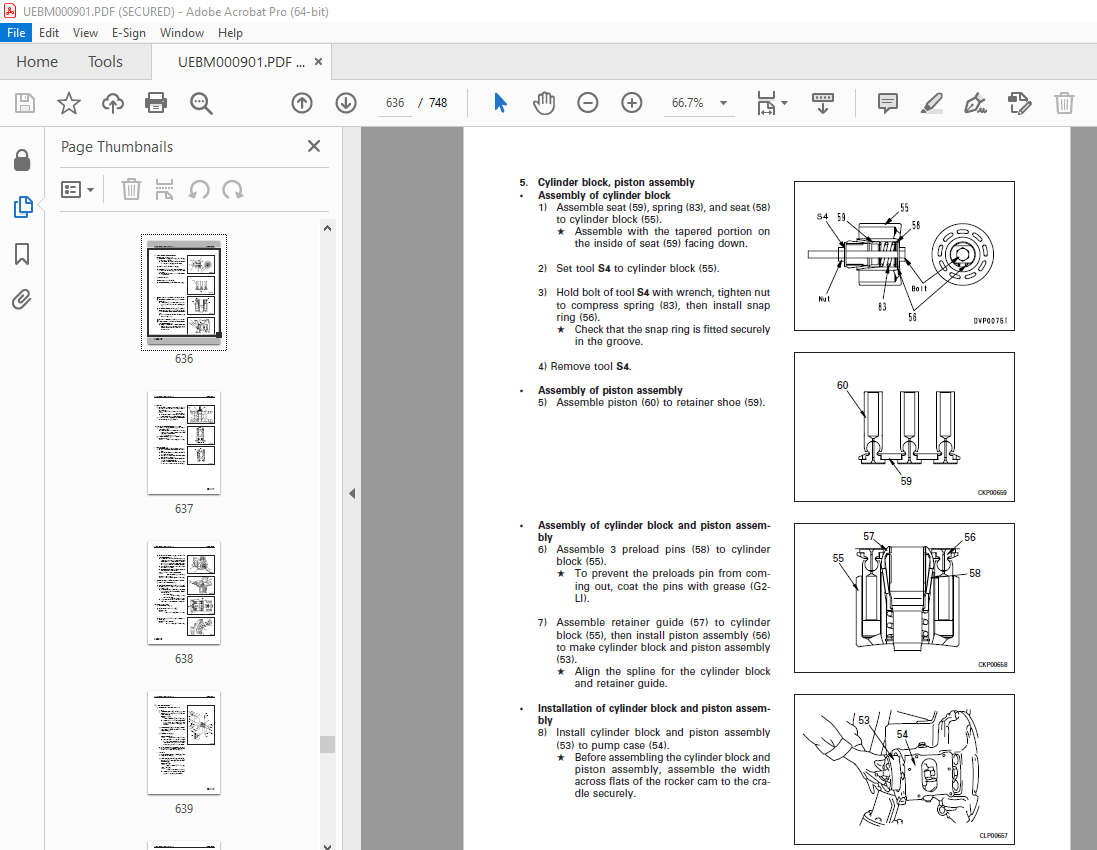
TABLE OF CONTENTS:
Komatsu PC340-6K PC340LC-6K PC340NLC-6K Excavator Shop Manual UEBM000901 – PDF DOWNLOAD
SERIAL NUMBERS
PC340-6K K32001, K34001 and up
PC340LC-6K K32001, K34001 and up
PC340NLC-6K K32001, K34001 and up
ENGINE 6D108E-2
SAFETY 3
SAFETY NOTICE 3
SAFETY SAFETY NOTICE GENERAL PRECAUTIONS 3
PREPARATIONS FOR WORK 3
SAFETY SAFETY NOTICE PRECAUTIONS DURING WORK 4
FOREWORD 5
GENERAL 5
STRUCTURE AND FUNCTION 5
TESTING AND ADJUSTING 5
DISASSEMBLY AND ASSEMBLY 5
MAINTENANCE STANDARD 5
FOREWORD FOREWORD GENERAL VOLUMES 6
Chassis volume: 6
Engine model: 6
Electrical volume: Attachments volume: 6
DISTRIBUTION AND UPDATING 6
FILING METHOD 6
10 – 3 6
1 2 – 5 6
REVISED EDITION MARK 6
REVISIONS 6
SYMBOLS 6
FOREWORD HOW TO READ THE SHOP MANUAL 6
HOW TO READ THE SHOP MANUAL 6
HOISTING INSTRUCTIONS 7
COATING MATERIALS 8
STANDARD TIGHTENING TORQUE 9
ELECTRIC WIRE CODE 11
CONVERSION TABLE 12
GENERAL 19
SPECIFICATION DRAWINGS 20
FUEL, COOLANT AND LUBRICANTS 26
STRUCTURE AND FUNCTION 29
PARTS RELATED TO ENGINE 30
RADIATOR, OIL COOLER 32
POWER TRAIN 33
FINAL DRIVE 34
SWING CIRCLE 35
SWING MACHINERY 36
TRACK FRAME, RECOIL SPRING 37
TRACK SHOE 38
HYDRAULIC PIPING DRAWING 40
HYDRAULIC CIRCUIT DIAGRAM 42
HYDRAULIC PUMP 45
CONTROL VALVE 66
SELF- REDUCING PRESSURE VALVE SUCTION SAFETY VALVE 81
CLSS 83
SWING MOTOR 148
CENTER SWIVEL JOINT 154
TRAVEL MOTOR 156
VALVE CONTROL 165
WORK EQUIPMENT Ł SWING PPC VALVE 166
TRAVEL PPC VALVE SERVICE PPC VALVE 174
PPC SAFETY LOCK VALVE 177
PPC ACCUMULATOR 177
PPC SHUTTLE VALVE, TRAVEL JUNCTION VALVE 179
LS- EPC VALVE 186
SOLENOID VALVE 190
WORK EQUIPMENT 198
AIR CONDITIONER 199
ACTUAL ELECTRIC WIRING DIAGRAM 200
ELECTRIC CIRCUIT DIAGRAM 204
ENGINE CONTROL 208
ELECTRONIC CONTROL SYSTEM 215
MACHINE MONITOR SYSTEM 242
TESTING AND ADJUSTING 253
STANDARD VALUE TABLE FOR ENGINE RELATED PARTS 256
STANDARD VALUE TABLE FOR CHASSIS RELATED PARTS 257
STANDARD VALUE TABLE FOR ELECTRICAL PARTS 265
TOOLS FOR TESTING, ADJUSTING, AND TROUBLESHOOTING 274
MEASURING ENGINE SPEED 275
MEASURING EXHAUST COLOR 276
ADJUSTING VALVE CLEARANCE 277
MEASURING COMPRESSION PRESSURE 278
MEASURING BLOW- BY PRESSURE 278
TESTING AND ADJUSTING FUEL INJECTION TIMING 279
MEASURING ENGINE OIL PRESSURE 280
TESTING AND ADJUSTING ALTERNATOR BELT TENSION 281
TESTING AND ADJUSTING WATER PUMP BELT TENSION 281
TESTING AND ADJUSTING BELT TENSION FOR AIR CONDITIONER COMPRESSOR 282
ADJUSTING ENGINE SPEED SENSOR 282
MEASURING AIR SUPPLY PRESSURE ( BOOST PRESSURE) 283
TESTING AND ADJUSTING GOVERNOR MOTOR LEVER STROKE 284
TESTING AND ADJUSTING HYDRAULIC PRESSURE IN WORK EQUIPMENT, SWING, TRAVEL CIRCUIT 285
TESTING AND ADJUSTING TVC VALVE OUTPUT PRESSURE ( SERVO PISTON INPUT PRESSURE) 288
TESTING AND ADJUSTING LS VALVE OUTPUT PRESSURE ( SERVO PISTON INPUT PRESSURE) AND LS DIFFERENTIAL PRESSURE 290
TESTING CONTROL CIRCUIT OIL PRESSURE ( OIL PRESSURE WHEN SELF- PRESSURE IS REDUCED) 293
TESTING SOLENOID VALVE OUTPUT PRESSURE 294
MEASURING PPC VALVE OUTPUT PRESSURE AND TESTING PPC SHUTTLE VALVE 297
ADJUSTING WORK EQUIPMENT, SWING PPC VALVE 299
TESTING TRAVEL DEVIATION 300
TESTING LOCATIONS CAUSING HYDRAULIC DRIFT OF WORK EQUIPMENT 301
MEASURING OIL LEAKAGE 303
RELEASING REMAINING PRESSURE IN HYDRAULIC CIRCUIT 305
TESTING CLEARANCE OF SWING CIRCLE BEARING 306
TESTING WEAR OF SPROCKET 307
TESTING AND ADJUSTING TRACK SHOE TENSION 308
BLEEDING AIR 309
POINTS TO REMEMBER WHEN TROUBLESHOOTING 312
CHECKS BEFORE TROUBLESHOOTING 322
CONNECTION TABLE FOR CONNECTOR PIN NUMBERS 329
EXPLANATION OF CONTROL MECHANISM FOR ELECTRICAL SYSTEM 339
DISPLAY METHOD AND SPECIAL FUNCTIONS OF MONITOR PANEL 340
METHOD OF USING JUDGEMENT TABLE 349
METHOD OF USING TROUBLESHOOTING CHARTS 351
DETAILS OF TROUBLESHOOTING AND TROUBLESHOOTING PROCEDURE 353
SERVICE CODE TABLE 358
TROUBLESHOOTING OF GOVERNOR, PUMP CONTROLLER ( GOVERNOR CONTROL SYSTEM) ( E MODE) 362
POINTS TO REMEMBER WHEN CARRYING OUT TROUBLESHOOTING OF GOVERNOR, PUMP CONTROLLER SYSTEM 363
ACTION TAKEN BY CONTROLLER WHEN ABNORMALITY OCCURS AND PROBLEMS ON MACHINE 365
JUDGEMENT TABLE FOR GOVERNOR, PUMP CONTROLLER ( GOVERNOR CONTROL SYSTEM) AND ENGINE RELATED PARTS 369
JUDGEMENT TABLE FOR GOVERNOR, PUMP CONTROLLER ( GOVERNOR CONTROL SYSTEM) AND ENGINE RELATED PARTS 369
E- 1 Abnormality in governor, pump controller power source ( controller LED is OFF) 373
E- 2 [ E308] Abnormality in fuel control dial input value is displayed 374
E- 3 [ E317] Abnormality ( disconnection) in motor drive system is displayed 375
E- 4 [ E318] Abnormality ( short circuit) in motor drive system is displayed 376
E- 5 [ E306] Abnormality in feedback potentiometer system is displayed 377
E- 6 [ E315] Abnormality ( short circuit) in battery relay output system is displayed 378
E- 7 [ E316] Abnormality ( step- out) in motor is displayed 379
E- 8 Engine does not start 381
E- 9 Engine speed is irregular 383
E- 10 Lack of output ( engine high idling speed is too low) 387
E- 11 Engine does not stop 389
E- 12 Defective operation of battery relay system ( engine does not stop) 391
TROUBLESHOOTING OF ENGINE SYSTEM ( S MODE) 393
S- 1 Starting performance is poor ( starting always takes time) 398
S- 2 Engine does not start 399
S- 3 Engine does not pick up smoothly ( follow- up is poor) 402
S- 4 Engine stops during operations 403
S- 5 Engine does not rotate smoothly ( hunting) 404
S- 6 Engine lacks output ( no power) 405
S- 7 Exhaust smoke is black ( incomplete combustion) 406
S- 8 Oil consumption is excessive ( or exhaust smoke is blue) 407
S- 9 Oil becomes contaminated quickly 408
S- 10 Fuel consumption is excessive 409
S- 11 Oil is in cooling water, or water spurts back, or water level goes down 410
S- 12 Oil pressure caution lamp lights up ( drop in oil pressure) 411
S- 13 Oil level rises ( water, fuel in oil) 412
S- 14 Water temperature becomes too high ( overheating) 413
S- 15 Abnormal noise is made 414
S- 16 Vibration is excessive 415
TROUBLESHOOTING OF GOVERNOR, PUMP CONTROLLER ( PUMP CONTROL SYSTEM) ( C MODE) 416
C- 1 Abnormality in controller power source system ( controller LED is OFF) 431
C- 2 [ E232] Short circuit in front pump TVC solenoid system is displayed 432
C- 3 [ E233] Disconnection in front pump TVC solenoid system is displayed 434
C- 4 [ E236] Short circuit in rear pump TVC solenoid system is displayed 436
C- 5 [ E237] Disconnection in rear pump TVC solenoid system is displayed 438
C- 6 [ E207] Short circuit in active mode ( boom) solenoid system is displayed 440
C- 7 [ E208] Disconnection in active mode ( boom) solenoid system is displayed 441
C- 8 [ E203] Short circuit in swing brake solenoid system is displayed 442
C- 9 [ E213] Disconnection in swing brake solenoid system is displayed 444
C- 10 [ E204] Short circuit in pump merge/ divider solenoid system is displayed 446
C- 11 [ E214] Disconnection in pump merge/ divider solenoid system is displayed 447
C- 12 [ E206] Short circuit in travel speed solenoid system is displayed 448
C- 13 [ E216] Disconnection in travel speed selector solenoid system is displayed 449
C- 14 [ E231] Short circuit in active mode ( swing) solenoid system is displayed 450
C- 15 [ E235] Disconnection in active mode ( swing) solenoid system is displayed 451
C- 16 [ E217] Model selection input error is displayed 452
C- 17 [ E222] Short circuit in LS- EPC solenoid system is displayed 454
C- 18 [ E223] Disconnection in LS- EPC solenoid system is displayed 455
C- 19 [ E224] Abnormality in front pump pressure sensor system is displayed 456
C- 20 [ E225] Abnormality in rear pump pressure sensor system is displayed 457
C- 21 [ E226] Abnormality in pressure sensor power source system is displayed 458
C- 22 [ E227] Abnormality in engine speed sensor system is displayed 459
C- 23 Abnormality in machine push- up solenoid system ( no service code displayed) 460
TROUBLESHOOTING OF GOVERNOR, PUMP CONTROLLER ( INPUT SIGNAL SYSTEM) ( F MODE) 464
F- 1 Bit pattern 20-( 1) Swing oil pressure switch does not light up 467
F- 2 Bit pattern 20-( 2) Travel oil pressure switch does not light up 468
F- 3 Bit pattern 20-( 3) Boom LOWER oil pressure switch does not light up 469
F- 4 Bit pattern 20-( 4) Boom RAISE oil pressure switch does not light up 470
F- 5 Bit pattern 20-( 5) Arm IN oil pressure switch does not light up 471
F- 6 Bit pattern 20-( 6) Arm OUT oil pressure switch does not light up 472
F- 7 Bit pattern 21-( 1) Bucket CURL oil pressure switch does not light up 473
F- 8 Bit pattern 21-( 2) Bucket DUMP oil pressure switch does not light up 474
F- 9 Bit pattern 21-( 3) Swing lock switch does not light up 475
F- 10 Bit pattern 22-( 5) Kerosene mode connection does not light up 476
F- 11 Bit pattern 22-( 6) L H knob switch does not light up 477
TROUBLESHOOTING OF HYDRAULIC, MECHANICAL SYSTEM ( H MODE) 478
H- 1 Speeds of all work equipment, swing, travel are slow or lack power 485
H- 2 There is excessive drop in engine speed, or engine stalls 487
H- 3 No work equipment, travel, swing move H- 4 Abnormal noise generated ( around pump) H- 5 Auto- deceleration does not work ( when PPC shuttle valve is cause) 489
H- 6 Fine control ability is poor or response is poor H- 7 Boom is slow or lacks power 491
H- 8 Arm is slow or lacks power 493
H- 9 Bucket is slow or lacks power 495
H- 10 Work equipment ( boom, arm, bucket) does not move ( but travel and swing are normal) 496
H- 11 Excessive hydraulic drift ( boom, arm, bucket) 496
H- 12 Excessive time lag ( engine at low idling) 497
H- 13 Other equipment moves when single circuit is relieved H- 14 In L/ O, F/ O modes, work equipment speed is faster than specified speed 498
H- 15 Defective actuation of machine push- up function 498
H- 16 In compound operations, work equipment with larger load is slow 498
H- 17 In swing + boom RAISE, boom RAISE is slow 499
H- 18 In swing + arm, arm is slow 499
H- 19 In swing + travel, travel speed drops excessively 499
H- 20 Travel deviation 500
H- 21 Travel speed is slow 501
H- 22 Steering does not turn easily or lacks power 503
H- 23 Travel speed does not switch or is faster than specified speed 505
H- 24 Travel does not move ( one side only) 505
H- 25 Does not swing 506
H- 26 Swing acceleration is poor or swing speed is slow 507
H- 27 Excessive overrun when stopping swing 509
H- 28 Excessive shock when stopping swing ( one direction only) H- 29 Excessive abnormal noise when stopping swing 510
H- 30 Excessive hydraulic drift of swing 511
H- 31 Swing speed is faster than specified swing speed 512
TROUBLESHOOTING OF MACHINE MONITOR SYSTEM ( M MODE) 513
M- 1 [ E101] Abnormality in error data is displayed [ E102] Error in clock data is displayed 520
M- 2 [ E103] Short circuit in buzzer output or contact of 24V wiring harness with buzzer drive harness is displayed 521
M- 3 [ E104] Air cleaner clogging detected is displayed 522
M- 4 [ E106] Drop in engine oil Hi pressure detected is displayed 522
M- 5 [ E108] Engine water temperature 105 ° C detected is displayed 523
M- 6 When starting switch is turned ON, none of lamps on monitor panel light up for 3 seconds 524
M- 7 When starting switch is turned ON, monitor panel lamps all stay lighted up and do not go out M- 8 When starting switch is turned ON, items lighted up on monitor panel are different from actual machine ( model) 526
M- 9 When starting switch is turned ON ( engine stopped), basic check items flash 527
M- 10 Preheating is not being used but ( preheating monitor) lights up 530
M- 11 When starting switch is turned ON and engine is started, basic check items flash 531
M- 12 When starting switch is turned ON ( engine stopped), caution items, emergency items flash ( battery, engine oil pressure lamps do not light up) 533
M- 13 When starting switch is turned ON and engine is started, caution items, emergency items flash ( when there is no abnormality in engine or items to check before troubleshooting) 535
M- 14 When starting switch is turned ON ( engine stopped), buzzer does not sound for 1 second Caution item flashes but buzzer does not sound 538
M- 15 No abnormality is displayed on monitor but buzzer sounds 538
M- 16 Night lighting on monitor panel does not light up ( liquid crystal display is normal) 539
M- 17 Coolant temperature gauge does not rise 540
M- 18 Coolant temperature gauge does not give any display ( none of gauge lamps light up during operation) 540
M- 19 Fuel level gauge always displays FULL 541
M- 20 Fuel level gauge does not give display 541
M- 21 Swing lock switch is turned ON ( LOCK) but ( swing lock monitor) does not light up 542
M- 22 Swing prolix switch is turned ON ( prolix), but ( swing lock monitor) does not flash 542
M- 23 Service meter does not advance while engine is running M- 24 When starting switch is at OFF and time switch is pressed, time and service meter are not displayed M- 25 Defective fuel level sensor system 544
M- 26 Defective coolant temperature sensor system 545
M- 27 Defective engine oil level sensor system 546
M- 28 Defective coolant level sensor system 547
M- 29 Defective hydraulic oil level sensor system 548
M- 30 Wiper does not work, or switch is not being used but wiper is actuated ( include E112, E113) 550
M- 31 Washer motor does not work, or switch is not being used but washer motor is actuated ( include E114) 555
30 558
METHOD OF USING MANUAL 560
PRECAUTIONS WHEN CARRYING OUT OPERATION 562
SPECIAL TOOL LIST 564
SKETCHES OF SPECIAL TOOLS 567
REMOVAL OF STARTING MOTOR ASSEMBLY 569
INSTALLATION OF STARTING MOTOR ASSEMBLY 569
REMOVAL OF ALTERNATOR ASSEMBLY 570
INSTALLATION OF ALTERNATOR ASSEMBLY 570
REMOVAL OF ENGINE OIL COOLER ASSEMBLY 571
INSTALLATION OF ENGINE OIL COOLER ASSEMBLY 571
REMOVAL OF FUEL INJECTION PUMP ASSEMBLY 572
INSTALLATION OF FUEL INJECTION PUMP ASSEMBLY 573
REMOVAL OF WATER PUMP ASSEMBLY 574
INSTALLATION OF WATER PUMP ASSEMBLY 574
REMOVAL OF NOZZLE HOLDER ASSEMBLY 575
INSTALLATION OF NOZZLE HOLDER ASSEMBLY 575
REMOVAL OF TURBOCHARGER ASSEMBLY 576
INSTALLATION OF TURBOCHARGER ASSEMBLY 576
REMOVAL OF THERMOSTAT ASSEMBLY 577
INSTALLATION OF THERMOSTAT ASSEMBLY 577
REMOVAL OF ENGINE FRONT SEAL 578
INSTALLATION OF ENGINE FRONT SEAL 579
REMOVAL OF ENGINE REAR SEAL 580
INSTALLATION OF ENGINE REAR SEAL 580
REMOVAL OF GOVERNOR MOTOR ASSEMBLY 582
INSTALLATION OF GOVERNOR MOTOR ASSEMBLY 582
REMOVAL OF CYLINDER HEAD ASSEMBLY 583
INSTALLATION OF CYLINDER HEAD ASSEMBLY 585
REMOVAL OF AFTERCOOLER ASSEMBLY 588
INSTALLATION OF AFTERCOOLER ASSEMBLY 588
REMOVAL OF HYDRAULIC COOLER ASSEMBLY 589
INSTALLATION OF HYDRAULIC COOLER ASSEMBLY 589
REMOVAL OF RADIATOR, HYDRAULIC COOLER ASSEMBLY 590
INSTALLATION OF RADIATOR, HYDRAULIC COOLER ASSEMBLY 591
REMOVAL OF ENGINE, MAIN PUMP ASSEMBLY 592
INSTALLATION OF ENGINE, MAIN PUMP ASSEMBLY 595
REMOVAL OF DAMPER ASSEMBLY 596
INSTALLATION OF DAMPER ASSEMBLY 596
REMOVAL OF FUEL TANK ASSEMBLY 597
INSTALLATION OF FUEL TANK ASSEMBLY 597
REMOVAL OF CENTER SWIVEL JOINT ASSEMBLY 598
INSTALLATION OF CENTER SWIVEL JOINT ASSEMBLY 598
DISASSEMBLY OF CENTER SWIVEL JOINT ASSEMBLY 599
ASSEMBLY OF CENTER SWIVEL JOINT ASSEMBLY 599
REMOVAL OF FINAL DRIVE ASSEMBLY 600
INSTALLATION OF FINAL DRIVE ASSEMBLY 600
DISASSEMBLY OF FINAL DRIVE ASSEMBLY 601
ASSEMBLY OF FINAL DRIVE ASSEMBLY 605
DISASSEMBLY OF TRAVEL MOTOR ASSEMBLY 613
ASSEMBLY OF TRAVEL MOTOR ASSEMBLY 618
DISASSEMBLY OF MAIN PUMP ASSEMBLY 627
ASSEMBLY OF MAIN PUMP ASSEMBLY 633
DISASSEMBLY OF PUMP MERGE/ DIVIDER VALVE ASSEMBLY 647
ASSEMBLY OF PUMP MERGE/ DIVIDER VALVE ASSEMBLY 647
DISASSEMBLY OF PRESSURE COMPENSATION VALVE ASSEMBLY 648
ASSEMBLY OF PRESSURE COMPENSATION VALVE ASSEMBLY 648
REMOVAL OF SERVO VALVE ASSEMBLY FOR FRONT PUMP 649
INSTALLATION OF SERVO VALVE ASSEMBLY FOR FRONT PUMP 649
REMOVAL OF SERVO VALVE ASSEMBLY FOR REAR PUMP 650
INSTALLATION OF SERVO VALVE ASSEMBLY FOR REAR PUMP 650
REMOVAL OF LS- EPC SOLENOID VALVE ASSEMBLY 651
INSTALLATION OF LS- EPC SOLENOID VALVE ASSEMBLY 651
REMOVAL OF SOLENOID VALVE ASSEMBLY 652
INSTALLATION OF SOLENOID VALVE ASSEMBLY 652
REMOVAL OF WORK EQUIPMENT PPC VALVE ASSEMBLY 653
INSTALLATION OF WORK EQUIPMENT, PPC VALVE ASSEMBLY 653
DISASSEMBLY OF WORK EQUIPMENT PPC VALVE ASSEMBLY 654
ASSEMBLY OF WORK EQUIPMENT PPC VALVE ASSEMBLY 655
REMOVAL OF TRAVEL PPC VALVE ASSEMBLY 656
INSTALLATION OF TRAVEL PPC VALVE ASSEMBLY 656
DISASSEMBLY OF TRAVEL PPC VALVE ASSEMBLY 657
ASSEMBLY OF TRAVEL PPC VALVE ASSEMBLY 658
REMOVAL OF PPC SHUTTLE VALVE ASSEMBLY 659
INSTALLATION OF PPC SHUTTLE VALVE ASSEMBLY 660
DISASSEMBLY OF PPC SHUTTLE VALVE ASSEMBLY 661
ASSEMBLY OF PPC SHUTTLE VALVE ASSEMBLY 662
REMOVAL OF BOOM CYLINDER ASSEMBLY 663
INSTALLATION OF BOOM CYLINDER ASSEMBLY 664
REMOVAL OF ARM CYLINDER ASSEMBLY 665
INSTALLATION OF ARM CYLINDER ASSEMBLY 666
REMOVAL OF BUCKET CYLINDER ASSEMBLY 667
INSTALLATION OF BUCKET CYLINDER ASSEMBLY 668
DISASSEMBLY OF HYDRAULIC CYLINDER ASSEMBLY 669
ASSEMBLY OF HYDRAULIC CYLINDER ASSEMBLY 672
REMOVAL OF WORK EQUIPMENT ASSEMBLY 676
INSTALLATION OF WORK EQUIPMENT ASSEMBLY 677
REMOVAL OF BUCKET ASSEMBLY 678
INSTALLATION OF BUCKET ASSEMBLY 679
REMOVAL OF ARM ASSEMBLY 680
INSTALLATION OF ARM ASSEMBLY 681
REMOVAL OF BUCKET, ARM ASSEMBLY 682
INSTALLATION OF BUCKET, ARM ASSEMBLY 683
REMOVAL OF BOOM ASSEMBLY 684
INSTALLATION OF BOOM ASSEMBLY 685
REMOVAL OF COUNTERWEIGHT ASSEMBLY 688
INSTALLATION OF COUNTERWEIGHT ASSEMBLY 688
REMOVAL OF AIR CONDITIONER COMPRESSOR ASSEMBLY 689
INSTALLATION OF AIR CONDITIONER COMPRESSOR ASSEMBLY 689
REMOVAL OF AIR CONDITIONER CONDENSER ASSEMBLY 690
INSTALLATION OF CONDENSER ASSEMBLY 690
REMOVAL OF RECEIVER TANK ASSEMBLY 691
INSTALLATION OF RECEIVER TANK ASSEMBLY 691
REMOVAL OF AIR CONDITIONER UNIT ASSEMBLY 692
INSTALLATION OF AIR CONDITIONER UNIT ASSEMBLY 693
REMOVAL OF GOVERNOR, PUMP CONTROLLER ASSEMBLY 694
INSTALLATION OF GOVERNOR, PUMP CONTROLLER ASSEMBLY 694
REMOVAL OF MONITOR PANEL ASSEMBLY 695
INSTALLATION OF MONITOR PANEL ASSEMBLY 695
REMOVAL OF CONTROL STAND CASE 696
INSTALLATION OF CONTROL STAND CASE 697
MAINTENANCE STANDARD 698
ENGINE MOUNT 699
SWING MACHINERY SWING CIRCLE 703
FINAL DRIVE TRACK FRAME AND RECOIL SPRING 707
IDLER 709
CARRIER ROLLER 711
TRACK ROLLER 712
TRACK SHOE 713
HYDRAULIC PUMP 717
CONTROL VALVE 719
SELF- REDUCING PRESSURE VALVE 726
SUCTION- SAFETY VALVE 727
SWING MOTOR 728
TRAVEL MOTOR 729
TRAVEL PPC VALVE 731
PPC SHUTTLE VALVE, TRAVEL JUNCTION VALVE 733
LS- EPC VALVE 734
SOLENOID VALVE HYDRAULIC CYLINDER 738
WORK EQUIPMENT 740
DESCRIPTION:
Komatsu PC340-6K PC340LC-6K PC340NLC-6K Excavator Shop Manual UEBM000901 – PDF DOWNLOAD
SERIAL NUMBERS
PC340-6K K32001, K34001 and up
PC340LC-6K K32001, K34001 and up
PC340NLC-6K K32001, K34001 and up
ENGINE 6D108E-2
GENERAL PRECAUTIONS :
Mistakes in operation are extremely dangerous. Read the OPERATION & MAINTENANCE MANUAL carefully BEFORE operating the machine.
1. Before carrying out any greasing or repairs, read all the precautions given on the decals which are fixed to the machine.2. When carrying out any operation, always wear safety shoes and helmet. Do not wear loose work clothes, or clothes with buttons missing.● Always wear safety glasses when hitting parts with a hammer.● Always wear safety glasses when grinding parts with a grinder, etc.3. If welding repairs are needed, always have a trained, experienced welder carry out the work. When carrying out welding work, always wear welding gloves, apron, glasses, cap and other clothes suited for welding work.4. When carrying out any operation with two or more workers, always agree on the operating procedure before starting. Always inform your fellow workers before starting any step of the operation. Before starting work, hang UNDER REPAIR signs on the controls in the operator’s compartment.5. Keep all tools in good condition and learn the correct way to use them.6. Decide a place in the repair workshop to keep tools and removed parts. Always keep the tools and parts in their correct places. Always keep the work area clean and make sure that there is no dirt or oil on the floor. Smoke only in the areas provided for smoking. Never smoke while working.
PREPARATIONS FOR WORK:
7. Before adding oil or making repairs, park the machine on hard, level ground, and block the wheels or tracks to prevent the machine from moving.8. Before starting work, lower blade, ripper, bucket or any other work equipment to the ground. If this is not possible, insert the safety pin or use blocks to prevent the work equipment from falling. In addition, be sure to lock all the control levers and hang warning signs on them.9. When disassembling or assembling, support the machine with blocks, jacks or stands before starting work.10. Remove all mud and oil from the steps or other places used to get on and off the machine. Always use the handrails, ladders or steps when getting on or off the machine. Never jump on or off the machine. If it is impossible to use the handrails, ladders or steps, use a stand to provide safe footing.
PRECAUTIONS DURING WORK :
11. When removing the oil filler cap, drain plug or hydraulic pressure measuring plugs, loosen them slowly to prevent the oil from spurting out. Before disconnecting or removing components of the oil, water or air circuits, first remove the pressure completely from the circuit.12. The water and oil in the circuits are hot when the engine is stopped, so be careful not to get burned. Wait for the oil and water to cool before carrying out any work on the oil or water circuits.13. Before starting work, remove the leads from the battery. ALWAYS remove the lead from the negative (-) terminal first.
More products