$32
Komatsu PC3400-11M0 Hydraulic Excavator Field Assembly Instruction Manual GEN00237-00 – PDF DOWNLOAD
Komatsu PC3400-11M0 Hydraulic Excavator Field Assembly Instruction Manual GEN00237-00 – PDF DOWNLOAD
FILE DETAILS:
Komatsu PC3400-11M0 Hydraulic Excavator Field Assembly Instruction Manual GEN00237-00 – PDF DOWNLOAD
Language : English
Pages : 299
Downloadable : Yes
File Type : PDF
Size: 34.1 MB
IMAGES PREVIEW OF THE MANUAL:

DESCRIPTION:
Komatsu PC3400-11M0 Hydraulic Excavator Field Assembly Instruction Manual GEN00237-00 – PDF DOWNLOAD
SERIAL NUMBERS 36301 and up
The Komatsu PC3400-11M0 Hydraulic Excavator Field Assembly Instruction Manual, with part number GEN00237-00, is a comprehensive guide that provides detailed instructions for assembling the Komatsu PC3400-11M0 hydraulic excavator. This manual is designed to help technicians and operators to correctly and efficiently assemble the excavator and ensure its proper operation in the field.
- The manual contains a wealth of information that is presented in a clear and concise manner, with detailed diagrams, illustrations, and step-by-step instructions that guide the assembly process. The manual covers a wide range of topics, including the assembly of the engine, the hydraulic system, the undercarriage, the cab, and the various components that make up the excavator.
- The manual is divided into several sections, each of which covers a specific aspect of the assembly process. The first section of the manual provides an overview of the assembly process, including safety precautions that must be taken during the assembly process. The second section provides detailed instructions for assembling the engine, including the installation of the fuel system, the cooling system, and the various other components that make up the engine.
- The third section of the manual covers the assembly of the hydraulic system, including the installation of the hydraulic pumps, cylinders, and other components. The fourth section covers the assembly of the undercarriage, including the installation of the tracks, rollers, and other undercarriage components.
- The fifth section of the manual covers the assembly of the cab, including the installation of the various controls and instruments that make up the operator’s station. The sixth section covers the assembly of the boom, arm, and bucket, including the installation of the various hydraulic cylinders and other components that make up these critical components of the excavator.
- In addition to the detailed instructions for assembly, the manual also provides information on the various tools and equipment that are required for the assembly process. The manual also includes a list of recommended spare parts and consumables that should be kept on hand to ensure that the excavator can be quickly and efficiently repaired in the field if necessary.
- Overall, the Komatsu PC3400-11M0 Hydraulic Excavator Field Assembly Instruction Manual is an essential resource for anyone involved in the assembly or maintenance of the Komatsu PC3400-11M0 hydraulic excavator. The manual provides a wealth of information and guidance that is designed to help ensure that the excavator is assembled correctly and operates reliably in the field.
TABLE OF CONTENTS:
Komatsu PC3400-11M0 Hydraulic Excavator Field Assembly Instruction Manual GEN00237-00 – PDF DOWNLOAD
COVER………………………………………………………………………………………………………… 1
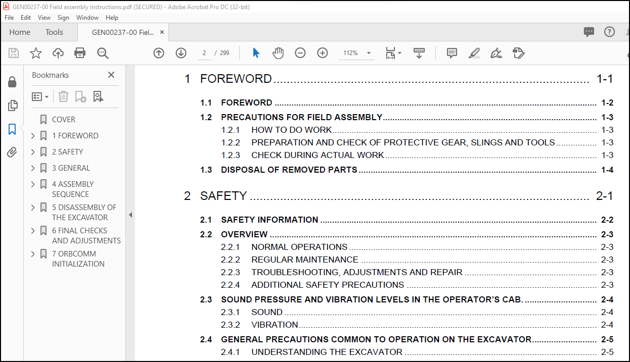
1 FOREWORD……………………………………………………………………………………………………. 8
1.1 Foreword………………………………………………………………………………………………. 9
1.2 Precautions for field assembly…………………………………………………………………………… 10
1.2.1 How to do work……………………………………………………………………………………. 10
1.2.2 Preparation and check of protective gear, slings and tools…………………………………………….. 10
1.2.3 Check during actual work…………………………………………………………………………… 10
1.3 Disposal of removed parts……………………………………………………………………………….. 11
2 SAFETY……………………………………………………………………………………………………… 12
2.1 SAFETY INFORMATION……………………………………………………………………………………… 13
2.2 OVERVIEW………………………………………………………………………………………………. 14
2.2.1 NORMAL OPERATIONS…………………………………………………………………………………. 14
2.2.2 REGULAR MAINTENANCE……………………………………………………………………………….. 14
2.2.3 TROUBLESHOOTING, ADJUSTMENTS AND REPAIR……………………………………………………………… 14
2.2.4 ADDITIONAL SAFETY PRECAUTIONS………………………………………………………………………. 14
2.3 SOUND PRESSURE AND VIBRATION LEVELS IN THE OPERATOR’S CAB…………………………………………………… 15
2.3.1 SOUND……………………………………………………………………………………………. 15
2.3.2 VIBRATION………………………………………………………………………………………… 15
2.4 GENERAL PRECAUTIONS COMMON TO OPERATION ON THE EXCAVATOR……………………………………………………. 16
2.4.1 UNDERSTANDING THE excavator………………………………………………………………………… 16
2.4.2 PRECAUTIONS BEFORE STARTING OPERATION ON THE EXCAVATOR………………………………………………… 16
2.4.2.1 ENSURING SAFE OPERATION………………………………………………………………………. 16
2.4.3 PREPARATIONS FOR SAFE OPERATION…………………………………………………………………….. 16
2.4.3.1 PRECAUTIONS REGARDING SAFETY RELATED EQUIPMENT………………………………………………….. 16
2.4.3.2 INSPECTING THE excavator……………………………………………………………………… 16
2.4.3.3 WEAR WELL FITTING CLOTHES AND PROTECTIVE EQUIPMENT………………………………………………. 17
2.4.3.4 KEEP excavator CLEAN…………………………………………………………………………. 17
2.4.3.5 PRECAUTIONS INSIDE OPERATOR’S COMPARTMENT………………………………………………………. 17
2.4.3.6 PROVIDE FIRE EXTINGUISHER AND FIRST AID KIT…………………………………………………….. 18
2.4.3.7 IF A PROBLEM IS FOUND………………………………………………………………………… 18
2.4.4 FIRE PREVENTION…………………………………………………………………………………… 18
2.4.4.1 PRECAUTIONS TO PREVENT FIRE…………………………………………………………………… 18
2.4.4.2 ACTION IF FIRE OCCURS, EMERGENCY EXIT FROM OPERATOR’S CAB………………………………………… 20
2.4.5 PRECAUTIONS WHEN GETTING ON OR OFF THE EXCAVATOR……………………………………………………… 21
2.4.5.1 USE HANDRAILS AND STEPS WHEN GETTING ON OR OFF THE EXCAVATOR……………………………………… 21
2.4.5.2 NO JUMPING ON OR OFF THE excavator…………………………………………………………….. 21
2.4.5.3 NO PEOPLE ON THE ATTACHMENT…………………………………………………………………… 21
2.4.5.4 WORKING IN HIGH PLACES……………………………………………………………………….. 21
2.4.5.5 LEAVING OPERATOR’S SEAT WITH LOCK……………………………………………………………… 22
2.4.5.6 LEAVING THE excavator………………………………………………………………………… 22
2.4.6 BURN PREVENTION…………………………………………………………………………………… 22
2.4.6.1 Hot coolant…………………………………………………………………………………. 22
2.4.6.2 Hot oil…………………………………………………………………………………….. 23
2.4.7 PRECAUTIONS WHEN CLEANING CAB GLASS…………………………………………………………………. 23
2.4.8 PRECAUTIONS RELATED TO PROTECTIVE STRUCTURES…………………………………………………………. 23
2.4.9 PRECAUTIONS RELATED TO AIRBOURNE AND EJECTED DEBRIS…………………………………………………… 24
2.4.9.1 UNAUTHORIZED MODIFICATION…………………………………………………………………….. 24
2.4.9.2 PRECAUTIONS RELATED TO ATTACHMENTS AND OPTIONS………………………………………………….. 24
2.4.10 ELECTROMAGNETIC COMPATIBILITY (EMC)………………………………………………………………… 24
2.4.11 PRECAUTIONS AT JOBSITE……………………………………………………………………………. 25
2.4.11.1 VISIBILITY FROM OPERATOR’S SEAT………………………………………………………………. 26
2.4.11.2 Proximity VISIBILITY………………………………………………………………………… 26
2.4.11.3 12m radius visibility……………………………………………………………………….. 26
2.4.11.4 24 m Radius visibility………………………………………………………………………. 26
2.4.11.5 CHECKING SIGNS AND SIGNALMAN’S SIGNALS………………………………………………………… 27
2.4.11.6 INVESTIGATE AND CONFIRM JOBSITE CONDITIONS…………………………………………………….. 27
2.4.11.7 DO NOT GO CLOSE TO HIGH VOLTAGE CABLES………………………………………………………… 27
2.4.11.8 Lightning Strikes…………………………………………………………………………… 28
2.4.11.9 WORKING ON LOOSE GROUND……………………………………………………………………… 28
2.4.11.10 GAS, DUST, STEAM, SMOKE AND EXHAUST FUMES…………………………………………………….. 28
2.4.11.11 VENTILATION OF ENCLOSED AREAS……………………………………………………………….. 29
2.4.12 STARTING motor…………………………………………………………………………………… 30
2.4.12.1 WARNING TAG………………………………………………………………………………… 30
2.4.12.2 CHECKS BEFORE STARTING motor…………………………………………………………………. 30
2.4.12.3 PRECAUTION WHEN STARTING motor……………………………………………………………….. 30
2.4.12.4 PRECAUTION IN COLD AREAS…………………………………………………………………….. 31
2.4.13 OPERATION……………………………………………………………………………………….. 31
2.4.13.1 CHECKS BEFORE OPERATION……………………………………………………………………… 31
2.4.13.2 PRECAUTIONS WHEN TRAVELING IN FORWARD OR REVERSE……………………………………………….. 32
2.4.13.3 PRECAUTIONS WHEN traveling…………………………………………………………………… 33
2.4.13.4 TRAVELING ON SLOPES…………………………………………………………………………. 34
2.4.13.5 OPERATIONS ON SLOPES………………………………………………………………………… 35
2.4.13.6 PROHIBITED OPERATIONS……………………………………………………………………….. 35
2.4.13.7 TRAVELING ON FROZEN OR SNOW COVERED SURFACES…………………………………………………… 36
2.4.13.8 PARKING THE excavator……………………………………………………………………….. 36
2.4.13.9 TRANSPORTATION……………………………………………………………………………… 36
2.5 PRECAUTION FOR MAINTENANCE………………………………………………………………………………. 37
2.5.1 GENERAL PRECAUTIONS……………………………………………………………………………….. 37
2.5.1.1 SELECTION AND QUALIFICATION OF PERSONNEL – BASIC RESPONSIBILITIES…………………………………. 38
2.5.1.2 STOP motor FOR MAINTENANCE……………………………………………………………………. 39
2.5.1.3 WARNING TAG…………………………………………………………………………………. 40
2.5.1.4 Power sockets……………………………………………………………………………….. 42
2.5.1.5 KEEP WORKPLACE CLEAN AND TIDY…………………………………………………………………. 42
2.5.1.6 APPOINT SUPERVISOR WHEN WORKING WITH OTHERS…………………………………………………….. 42
2.5.1.7 TWO WORKERS FOR MAINTENANCE WHEN THE excavator IS RUNNING………………………………………… 43
2.5.1.8 INSTALLING, REMOVING OR STORING ATTACHMENTS…………………………………………………….. 43
2.5.1.9 PRECAUTIONS WHEN WORKING UNDER THE excavator OR EQUIPMENT………………………………………… 44
2.5.1.10 NOISE……………………………………………………………………………………… 44
2.5.1.11 WHEN USING A HAMMER…………………………………………………………………………. 44
2.5.1.12 PROPER TOOLS……………………………………………………………………………….. 45
2.5.1.13 ACCUMULATOR………………………………………………………………………………… 45
2.5.1.14 PERSONNEL………………………………………………………………………………….. 45
2.5.2 PRECAUTIONS FOR INSPECTION AND MAINTENANCE…………………………………………………………… 46
2.5.2.1 PRECAUTION WHEN WELDING………………………………………………………………………. 46
2.5.2.2 BATTERY HANDLING…………………………………………………………………………….. 46
2.5.3 PRECAUTIONS WITH HIGH PRESSURE FLUID………………………………………………………………… 47
2.5.3.1 PRECAUTIONS WITH HIGH FUEL PRESSURE……………………………………………………………. 48
2.5.3.2 HANDLING HIGH PRESSURES HOSES OR PIPES…………………………………………………………. 49
2.5.3.3 REPLACEMENT OF HOSE LINES…………………………………………………………………….. 49
2.5.3.4 INSPECTION OF HOSE LINES……………………………………………………………………… 49
2.5.3.5 PERIODIC REPLACEMENT OF SAFETY CRITICAL PARTS…………………………………………………… 50
2.5.3.6 AIR CONDITIONING MAINTENANCE………………………………………………………………….. 50
2.5.3.7 COMPRESSED AIR………………………………………………………………………………. 50
2.5.3.8 WASTE MATERIALS……………………………………………………………………………… 51
2.6 ADDITIONAL SAFETY INFORMATION FOR TROUBLESHOOTING AND ADJUSTMENTS……………………………………………. 52
2.6.1 INSPECTION OF THE HYDRAULIC SYSTEM………………………………………………………………….. 52
2.6.2 TWO WORKERS ONLY WHEN THE EXCAVATOR IS RUNNING DURING ADJUSTMENTS………………………………………. 52
2.6.3 AREAS OF POTENTIAL DANGER AROUND THE EXCAVATOR……………………………………………………….. 52
2.7 SPECIAL SAFETY EQUIPMENT………………………………………………………………………………… 53
2.7.1 FRONT GUARD PROTECTIVE Structure ’FOPS’ FOR OPERATOR’S CAB…………………………………………….. 54
2.7.2 OBJECT HANDLING…………………………………………………………………………………… 54
2.7.3 LIGHTING…………………………………………………………………………………………. 54
2.7.4 WARNING BEACON……………………………………………………………………………………. 54
2.7.5 SAFETY HARNESS IN CONFORMITY WITH EN 361 (EUROPEAN STANDARD)…………………………………………… 54
2.7.5.1 INSTRUCTIONS FOR USE…………………………………………………………………………. 56
2.7.5.2 PRIOR TO USING THE HARNESS (1), THE WEARER SHALL………………………………………………… 58
2.7.5.3 RECOMMENDATIONS FOR USE OF THE HOLDING HOOKS AND HOLD- BACK HOOKS OF THE SAFETY HARNESS……………… 58
2.7.5.4 INSTRUCTIONS FOR USE…………………………………………………………………………. 60
3 GENERAL…………………………………………………………………………………………………….. 62
3.1 General……………………………………………………………………………………………….. 63
3.1.1 DELIVERY OF THE EXCAVATOR………………………………………………………………………….. 63
3.1.2 ASSEMBLING THE EXCAVATOR…………………………………………………………………………… 63
3.1.2.1 Checks prior to initial start-up………………………………………………………………. 63
3.1.3 LIFTING AND TRANSPORTATION…………………………………………………………………………. 64
3.1.4 ELECTRICAL ENERGY…………………………………………………………………………………. 64
3.1.5 ELECTROMAGNETIC COMPATIBILITY (EMC)…………………………………………………………………. 64
3.1.6 MONITORING SYSTEM OF THE Machine……………………………………………………………………. 64
3.2 Assembly site requirements………………………………………………………………………………. 65
3.2.1 Configuration of components on erection side (example)………………………………………………… 65
3.2.2 Required cranes…………………………………………………………………………………… 67
3.2.3 Manpower / Assembly Time…………………………………………………………………………… 67
3.2.4 Tools and equipment for assembly……………………………………………………………………. 68
3.3 Standard application for torque chart…………………………………………………………………….. 70
3.3.1 Metric standard thread…………………………………………………………………………….. 70
3.3.2 Metric fine thread………………………………………………………………………………… 71
3.4 Special Tightening Torques………………………………………………………………………………. 72
3.5 Torque for flange Joints………………………………………………………………………………… 73
3.6 Tightening Torque for hydraulic hose connecting nut………………………………………………………… 74
3.7 General installation procedures for hydraulic hose lines……………………………………………………. 75
3.8 General installation instructions for attachment pins………………………………………………………. 78
3.8.1 Preparations for assembyl………………………………………………………………………….. 80
3.9 Transportation Postures…………………………………………………………………………………. 81
4 ASSEMBLY SEQUENCE……………………………………………………………………………………………. 94
4.1 Assemble sequence………………………………………………………………………………………. 95
4.1.1 Assembly sequence under consideration of the excavator’s stability……………………………………… 95
4.2 Assemble the undercarriage (center body, track frames)……………………………………………………… 97
4.2.1 Preparations before working………………………………………………………………………… 97
4.2.2 Attach Center body to Track Frames………………………………………………………………….. 97
4.2.2.1 Attach Center body to L.H. Track Frame…………………………………………………………. 97
4.2.2.2 Attach R.H. Track Frame to Center body…………………………………………………………. 99
4.2.2.3 Determining the Tightening Torque………………………………………………………………101
4.2.3 Special hydraulic torque wrench……………………………………………………………………..104
4.2.4 Connect Hydraulic Lines to the Travel Motors………………………………………………………….105
4.2.5 Hydraulic Track Tensioning system……………………………………………………………………107
4.2.5.1 Connect Hydraulic Lines to the Track tensioning system……………………………………………109
4.2.6 Final Assembly of Undercarriage……………………………………………………………………..110
4.3 Assemble the main valve block assembly…………………………………………………………………….111
4.4 Assemble the superstructure platform………………………………………………………………………113
4.5 Assemble the machine house assembly……………………………………………………………………….119
4.5.1 Assemble the air cleaner Assembly……………………………………………………………………125
4.5.2 Assemble the exhaust muffler assembly………………………………………………………………..130
4.5.3 Assemble the handrails……………………………………………………………………………..135
4.5.4 Connect service center……………………………………………………………………………..137
4.6 Assemble the L.H. platform……………………………………………………………………………….139
4.7 Assemble hydraulically operated stairway…………………………………………………………………..151
4.8 Assemble the machine house L.H. platform…………………………………………………………………..155
4.9 Assemble the cab base……………………………………………………………………………………161
4.9.1 Assemble the cab base walks and attachments…………………………………………………………..167
4.10 Assemble the operator’s cab……………………………………………………………………………..173
4.11 Assemble the fuel tank top platform………………………………………………………………………181
4.12 Assemble the lubrication pump station…………………………………………………………………….183
4.13 Assemble the hydraulic oil tank………………………………………………………………………….187
4.13.1 Assemble the platform between machine house and hydraulic oil tank……………………………………..195
4.14 Assemble the superstructure floor frame…………………………………………………………………..199
4.15 Assemble the machine house r.h. platform………………………………………………………………….202
4.16 Assemble the hydraulic oil tank R.H. platform……………………………………………………………..203
4.17 Assemble the emergency escape ladder at the machine house…………………………………………………..205
4.18 Assemble the oil cooler assembly…………………………………………………………………………207
4.19 Pre-assemble boom & hydraulic cylinder……………………………………………………………………219
4.19.1 Preparatory work………………………………………………………………………………….219
4.19.1.1 Remove the pre-installed pins at the boom………………………………………………………222
4.19.1.2 Remove the pre-installed boom foot pins and boom cylinder foot pins from the superstructure platform….224
4.19.1.3 Remove the boom cylinder foot pin……………………………………………………………..224
4.19.1.4 Remove the pre-installed boom cylinder foot pins from the boom cylinders…………………………..225
4.19.2 Assemble the boom cylinders………………………………………………………………………..226
4.19.3 Assemble the stick cylinders……………………………………………………………………….229
4.20 Assemble the counterweight………………………………………………………………………………232
4.21 Install the Pre-assembled boom at the superstructure……………………………………………………….239
4.21.1 Install the boom cylinder at the superstructure………………………………………………………243
4.22 Connect the components and piping around the boom foot……………………………………………………..245
4.23 Pre-checks before engine start…………………………………………………………………………..249
4.23.1 Pre-checks prior to initial start up………………………………………………………………..249
4.23.2 Filling and bleeding the hydraulic system……………………………………………………………251
4.23.2.1 Filling the hydraulic system………………………………………………………………….253
4.23.2.2 Bleeding the hydraulic system…………………………………………………………………255
4.24 Install the stick at the boom……………………………………………………………………………263
4.25 Connect the stick cylinders and stick…………………………………………………………………….267
4.26 Connect the components and piping around the stick…………………………………………………………269
4.27 Bleeding the bucket cylinder…………………………………………………………………………….271
4.28 Assemble the bucket…………………………………………………………………………………….272
4.29 Bleed air from track tensioning system……………………………………………………………………276
4.30 Bleed slew circuit……………………………………………………………………………………..277
4.31 Bleed air from track system……………………………………………………………………………..278
5 DISASSEMBLY OF THE EXCAVATOR…………………………………………………………………………………..280
5.1 Disassembly sequence of backhoe excavators…………………………………………………………………281
5.1.1 Safety precautions for disassembling the excavator…………………………………………………….282
5.1.2 Disposal of the waste material………………………………………………………………………283
6 FINAL CHECKS AND ADJUSTMENTS…………………………………………………………………………………..284
6.1 Commissioning check list…………………………………………………………………………………285
6.2 Adjustment of automatic lubrication systems………………………………………………………………..286
6.2.1 Setting of pause time and grease injector output (continued)……………………………………………288
6.3 Charging air conditioner with refrigerant………………………………………………………………….290
6.4 Perform the PM – Clinic commissioning procedure according to the PM – Clinic manual…………………………….292
6.4.1 Visual inspection………………………………………………………………………………….293
6.4.2 Travelling inspection………………………………………………………………………………293
6.5 Handling of documentation after assembly and commissioning…………………………………………………..294
7 ORBCOMM INITIALIZATION………………………………………………………………………………………..296
7.1 PC configuration tool for KOMTRAX Plus / ORBCOMM……………………………………………………………297
7.2 KomVision Calibration……………………………………………………………………………………298
More products