$42
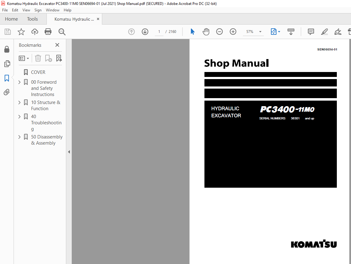
Komatsu PC3400-11M0 Series Engine Shop Manual SEN06694-01 – PDF DOWNLOAD
Komatsu PC3400-11M0 Series Engine Shop Manual SEN06694-01 – PDF DOWNLOAD
FILE DETAILS:
Komatsu PC3400-11M0 Series Engine Shop Manual SEN06694-01 – PDF DOWNLOAD
Language : English
Pages : 2160
Downloadable : Yes
File Type : PDF
Size: 190 MB
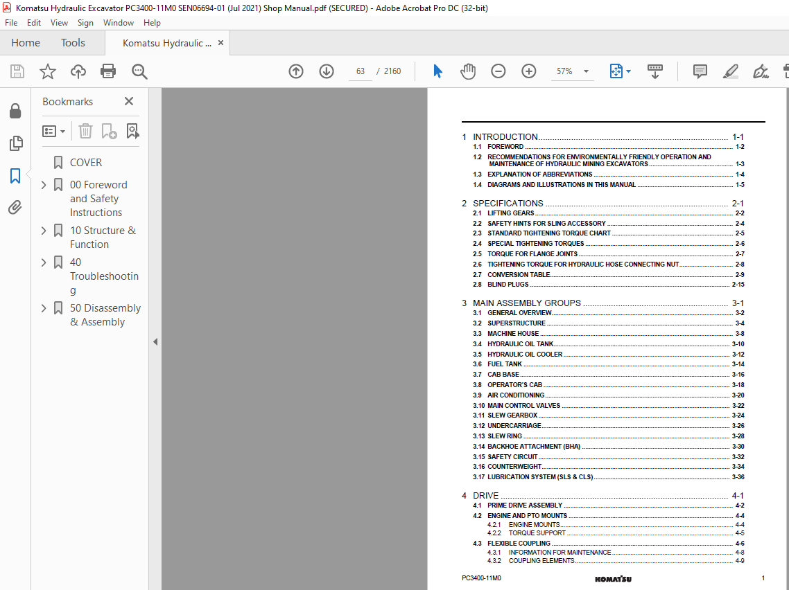
TABLE OF CONTENTS:
Komatsu PC3400-11M0 Series Engine Shop Manual SEN06694-01 – PDF DOWNLOAD
COVER 1
00 Foreword and Safety Instructions 3
1 FOREWORD 5
1 1 BEFORE READING THIS MANUAL 6
1 2 CONTENTS OF THIS BINDER 7
1 2 1 CONTACTING THE SERVICE 7
1 2 2 GUARANTEE 7
1 3 DIVISION OF THE BINDER 8
2 SAFETY 9
2 1 SAFETY INFORMATION 10
2 2 OVERVIEW 11
2 2 1 NORMAL OPERATIONS 11
2 2 2 REGULAR MAINTENANCE 11
2 2 3 TROUBLESHOOTING, ADJUSTMENTS AND REPAIR 11
2 2 4 ADDITIONAL SAFETY PRECAUTIONS 11
2 3 SOUND PRESSURE AND VIBRATION LEVELS INTHE OPERATOR’S CAB 12
2 3 1 SOUND 12
2 3 2 VIBRATION 12
2 4 GENERAL PRECAUTIONS COMMON TO OPERATIONON THE EXCAVATOR 13
2 4 1 UNDERSTANDING THE EXCAVATOR 13
2 4 2 PRECAUTIONS BEFORE STARTING OPERATION ON THEEXCAVATOR 13
2 4 3 PREPARATIONS FOR SAFE OPERATION 13
2 4 4 FIRE PREVENTION 15
2 4 5 PRECAUTIONS WHEN GETTING ON OR OFF THE EXCAVATOR 18
2 4 7 PRECAUTIONS WHEN CLEANING CAB GLASS 20
2 4 8 PRECAUTIONS RELATED TO PROTECTIVE STRUCTURES 20
2 4 9 PRECAUTIONS RELATED TO AIRBOURNE AND EJECTEDDEBRIS 21
2 4 10 ELECTROMAGNETIC COMPATIBILITY (EMC) 21
2 4 11 PRECAUTIONS AT JOBSITE 22
2 4 12 STARTING MOTOR 27
2 4 13 OPERATION 28
2 5 PRECAUTION FOR MAINTENANCE 34
2 5 1 GENERAL PRECAUTIONS 34
2 5 2 PRECAUTIONS FOR INSPECTION AND MAINTENANCE 43
2 5 3 PRECAUTIONS WITH HIGH PRESSURE FLUID 44
2 6 ADDITIONAL SAFETY INFORMATIONFOR TROUBLESHOOTING AND ADJUSTMENTS 49
2 6 1 INSPECTION OF THE HYDRAULIC SYSTEM 49
2 6 2 TWO WORKERS ONLY WHEN THE EXCAVATOR IS RUNNINGDURING ADJUSTMENTS 49
2 6 3 AREAS OF POTENTIAL DANGER AROUND THE EXCAVATOR 49
2 7 SPECIAL SAFETY EQUIPMENT 50
2 7 1 FRONT GUARD PROTECTIVE STRUCTURE ’FOPS’ FOROPERATOR’S CAB 51
2 7 2 OBJECT HANDLING 51
2 7 3 LIGHTING 51
2 7 4 WARNING BEACON 51
2 7 5 SAFETY HARNESS IN CONFORMITY WITH EN 361 (EUROPEANSTANDARD) 51
10 Structure & Function 61
1 Introduction 73
1 1 Foreword 74
1 2 Recommendations for environmentally friendly operation and maintenance of hydraulic mining excavators 75
1 3 Explanation of abbreviations 76
1 4 Diagrams and illustrations in this manual 77
2 Specifications 79
2 1 Lifting Gears 80
2 2 Safety hints for sling accessory 82
2 3 Standard Tightening Torque Chart 83
2 4 Special Tightening Torques 84
2 5 Torque for flange Joints 85
2 6 Tightening Torque for hydraulic hose connecting nut 86
2 7 Conversion Table 87
2 8 Blind plugs 93
3 Main assembly groups 97
3 1 General overview 98
3 2 Superstructure 100
3 3 Machine house 104
3 4 Hydraulic oil tank 106
3 5 Hydraulic oil cooler 108
3 6 Fuel tank 110
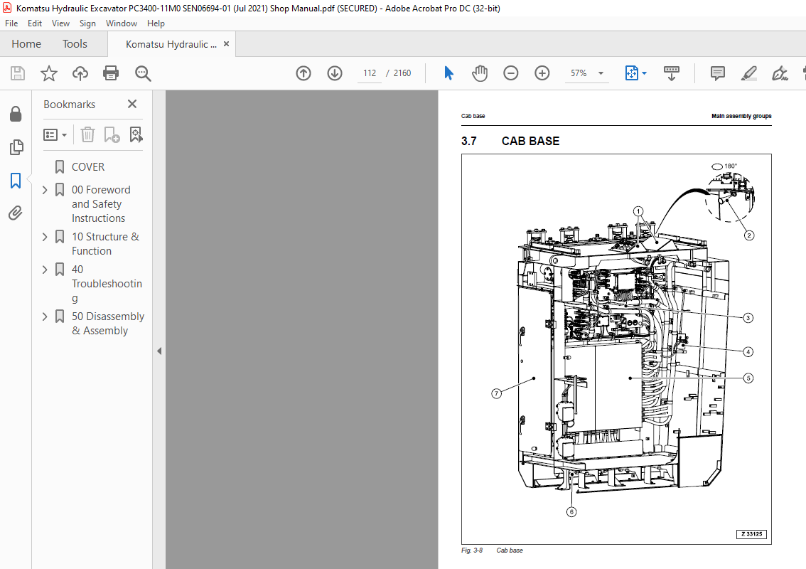
3 7 Cab base 112
3 8 Operator’s cab 114
3 9 Air conditioning 116
3 10 Main control valves 118
3 11 Slew Gearbox 120
3 12 Undercarriage 122
3 13 Slew ring 124
3 14 Backhoe attachment (BHA) 126
3 15 Safety circuit 128
3 16 Counterweight 130
3 17 Lubrication system (SLS & CLS) 132
4 Drive 135
4 1 Prime drive assembly 136
4 2 Engine and PTO mounts 138
4 2 1 Engine Mounts 138
4 2 2 Torque Support 139
4 3 Flexible coupling 140
4 3 1 Information for maintenance 142
4 3 2 Coupling elements 143
4 3 3 Separation and assembly of the coupling inner and outer part 144
4 3 4 Operation troubles, causes, and rectification 145
4 4 Fan drive and radiator assembly 146
4 4 1 Fan motor & fan assembly 148
4 4 2 Radiator fan drive 150
4 4 3 Fan pump 152
4 4 4 Radiator fan drive speed measurement and fan reverse function 154
4 5 Pump distributor gearbox (PTO) 156
4 5 1 Pump spline lubrication 158
4 5 2 PTO lubrication and cooling 160
4 6 Hydraulic pumps – location, drive speed and flow rates 168
4 6 1 Pump data 170
4 7 Air filter 172
5 Hydraulic oil tank 175
5 1 General layout 176
5 2 Hydraulic oil tank, location of the electric equipment 178
5 3 Suction oil tank with strainers 180
5 4 Bypass valve with strainer 182
5 5 Back pressure valve 184
5 6 Transfer pump 186
5 7 Return and leak oil filter 188
5 8 Breather filter 190
5 9 Hydraulic oil tank bleeding instruction 192
5 10 Return oil filter chamber sight gauge 196
6 Hydraulic oil cooling 199
6 1 Overall view of the hydraulic oil coolers 200
6 1 1 Fan motor & Fan assembly 202
6 1 2 Overall view of the hydraulic oil cooler fan drive circuit 204
6 1 3 Bypass valve 206
6 1 4 Bypass valve connections 208
6 2 Fan pump 212
6 3 Overview of the oil cooler circuit 214
6 3 1 Hydraulic oil cooling fan drive speed Measurement and fan reverse function 215
6 3 2 Inspection of the cooler core vibration absorbers 217
7 Controlling 219
7 1 General layout PPC line 220
7 2 Valve cartridge block 224
7 3 Pilot pressure supply 226
7 3 1 X1 pilot pressure circuit outline 226
7 3 2 X2 pilot pressure circuit outline 228
7 3 3 Pilot pressure circuit at main control valve blocks 230
7 3 4 Checks and adjustment of pilot pressure 232
7 4 Main control valves designation 234
7 5 Function of the electronic pump & bleed control system 238
7 5 1 Controller setting for Lever Control and Attachment Type in the excavator Configuration 240
7 5 2 Electronic hand lever (joystick) 244
7 6 Foot pedal control 246
7 7 Hand lever & foot pedal monitoring 249
7 7 1 Lever monitoring screens (example) 250
7 7 2 PPC signal information screen (example) 252
7 7 3 Solenoid Valve monitoring PPC circuit 254
7 8 Valve solenoid adjustment 258
7 8 1 Overview sol min/max current & adjustment range 259
7 9 ACCEL & DECEL time adjustment 260
7 9 1 Accel & Decel times 260
8 Components 263
8 1 Main control valves overview (BHA) 264
8 2 Main control valve designation (front) 266
8 3 Main control valve designation (rear) 268
8 4 Main control valves designation 270
8 5 Main control valve 1 and 2 272
8 6 Main control valve 3 274
8 7 Boom operation sample MCV 2 276
8 7 1 Neutral position 276
8 7 2 Boom raise 278
8 7 3 Boom lower 280
8 8 Spool types 282
8 9 Main control valves spool functions 284
8 9 1 Main control valve 1 284
8 9 2 Main control valve 2 286
8 9 3 Main control valve 3 288
8 10 Slow return valve 290
8 11 4/3 Directional solenoid valves 292
8 12 Solenoid valves 294
8 12 1 Operation of solenoid valve and check valve 296
8 13 Solenoid valve 298
8 14 EPC solenoid valve 302
8 15 High-pressure screen 304
8 16 Main relief valve 306
8 17 Suction & safety relief valve (SSRV) 308
8 18 Suction valve (SV) 310
8 19 Load check valve 312
8 20 Variable back pressure valve 314
8 21 Boom regeneration valve 316
8 22 Hydraulic cylinder 318
8 22 1 Bucket cylinder 318
8 22 2 Stick cylinder 322
8 22 3 Boom cylinder 324
8 22 4 Cylinder data markings 326
9 Main hydraulic pumps and pump regulation 327
9 1 General 328
9 1 1 Main pump and auxiliary pump bleeding procedure 330
9 1 2 Pump locations and pump datas 334
9 2 Main pumps 336
9 2 1 Hydraulic pump type HPV375+375 336
9 2 2 Servo valve 340
9 3 Electronic pump regulation system 350
9 3 1 Cut-off function 352
9 3 2 Temperature control 353
9 4 Valve controller (14K303 – 14K305) 354
9 5 Monitoring, error indication, adjustment 356
9 5 1 Monitoring items of the three Valve controllers 356
9 5 2 Error indication of the Three valve controllers 358
9 5 3 Adjustable parameters of the Three valve controllers 359
9 6 Checks and adjustments 361
9 6 1 Engine power check 361
9 6 2 Pump calibration 361
9 7 Engine speed sensor (pick-up) 367
9 7 1 General 368
9 7 2 Engine speed sensor (pick-up) adjustment 368
10 Operating hydraulics 371
10 1 General 372
10 1 1 3-circuit hydraulic system 372
10 2 Hydraulics for the attachment cylinders 374
10 2 1 Electric / hydraulic flowchart “boom up” (BHA) 374
10 2 2 Electric / hydraulic flowchart “Boom down” (BHA) 376
10 2 3 Electric / hydraulic flowchart “Stick out” (BHA) 378
10 2 4 Electric / hydraulic flowchart “Stick in” (BHA) 380
10 2 5 Electric / hydraulic flowchart “Bucket fill” (BHA) 382
10 2 6 Electric / hydraulic flowchart “Bucket dump” (BHA) 384
10 2 7 Checks & adjustments of the main relief valve (MRV) 386
10 2 8 Checks and adjustments of the lowering speed 388
10 2 9 Cushion function 394
10 3 Hydraulics for the slew circuit 406
10 3 1 Slew circuit 406
10 3 2 Slew motor 408
10 3 3 Slew gearbox 410
10 3 4 Slew parking brake 412
10 3 5 Slew brake valve 416
10 3 6 Double stage valve (DSV) 418
10 3 7 Electric / hydraulic flowchart “Slew left” 420
10 3 8 Electric / hydraulic flowchart “Slew right” 422
10 3 9 Checks for the slew circuit 424
10 3 10 Slew parking brake release function check 438
10 4 Hydraulics for the travel system 440
10 4 1 Travel circuit 440
10 4 2 Travel motor 444
10 4 3 Rotary joint 446
10 4 4 Travel gearbox 448
10 4 5 Travel parking brake 450
10 5 Travel brake valve 454
10 5 1 Electric / hydraulic flowchart “travel forward” 456
10 5 2 Electric / hydraulic flowchart “travel backwards” 458
10 5 3 Checks and adjustments 460
11 Hydraulic track tensioning system 467
11 1 General 468
11 2 Functional description 470
11 2 1 Valve cartridge block 472
11 2 2 Rotary joint 474
11 2 3 Track tensioning Valve block 476
11 2 4 Accumulator second stage 478
11 2 5 Accumulator first stage 480
11 2 6 Track tensioning cylinder 482
11 3 Tensioning cylinder 483
11 4 Double stage valve 484
11 5 Checks / Adjustments 486
12 Access stairway, hydraulically operated 489
12 1 General 490
12 2 Function of the hydraulically operated access stairway 492
12 3 Hydraulic schematic stairway movement 497
13 Central refilling system (Service arm) 499
13 1 General 500
13 2 Service arm connections 502
13 3 Refilling system layout 503
13 4 Grease refill and Auto Stop function 504
13 5 Function 506
14 Symbol explanation of hydraulic diagram 509
14 1 Reference code of the hydraulic components 510
14 1 1 Area code 510
14 1 2 Component identifying letter 512
14 2 Hydraulic symbols 513
14 2 1 Lines, unions 513
14 2 2 Components, valves 514
14 2 3 Sensors 515
14 2 4 Valves, valve components 515
14 2 5 Pump, motor, cylinder 519
15 Symbol explanation electric wiring diagram 523
15 1 Reference code of the electrical components 524
15 1 1 Area code 525
15 1 2 Component identifying letter 526
15 2 Cable and connector marking 528
15 3 Cable color identification 530
16 Monitoring & Control System 531
16 1 General 532
16 1 1 Monitoring & control system – overview 532
16 1 2 Controller system overview PC3400-11 T2 534
16 1 3 Interface connection 536
16 1 4 General description 538
16 2 Machine monitor – Operator level 540
16 2 1 Main gauge screens 542
16 2 2 Operator menus / Tabs / functions of keys F1 F6 548
16 3 Error and status indication on the operator level 576
16 3 1 Prompts (status indications) 576
16 3 2 Lock lever locked automatically 578
16 3 3 Cautions 580
16 3 4 Emergency shutdown screen 582
16 3 5 Fault levels for error messages 584
16 3 6 Action code level L01 585
16 3 7 Action code level L02 586
16 3 8 Action code level L03 587
16 3 9 Action code level L04 588
16 3 10 Error list 589
16 3 11 Failure codes without monitor indication 590
16 3 12 Additional text information for action codes 590
16 4 Table of failure codes 591
16 5 Table of C-codes – Diesel engine Tier2 622
16 6 Flow charts of machine monitor screens 639
16 6 1 Flow chart Operator Level 639
16 6 2 Flow chart Service Level 640
16 7 Machine monitor 641
16 7 1 Entering the Service Level 641
16 7 2 Softkey symbols (F1 F6) on the Service Level 643
16 7 3 Service Menu selection screens 644
16 8 Service Menu – item 01 Monitoring / Custom 645
16 8 1 Monitoring list for: ENG controller 645
16 8 2 Monitoring list for: VALVE M controller 647
16 8 3 Monitoring list for: VALVE 1 controller 651
16 8 4 Monitoring list for: VALVE 2 controller 654
16 8 5 Monitoring list for: VALVE 3 controller 657
16 8 6 Monitoring list for: MON (monitor) 660
16 8 7 Monitoring list for: KOM PLS (K+ controller) 662
16 8 8 How to perform the monitoring function 665
16 9 Service Menu – item 02 PM Clinic 667
16 9 1 PM Clinic (General) 667
16 9 2 PM Clinic (Power Check) 668
16 9 3 Functions of PM CLINIC (POWER CHECK) 669
16 10 Service Menu – item 03 Abnormality record 670
16 10 1 Reset error messages 672
16 11 Service Menu – item 04 Maintenance record 673
16 12 Service Menu – item 05 Maintenance Mode Setting 674
16 13 Service Menu – item 06 Snap Shot 676
16 14 Service Menu – item 07 Phone Number Entry 677
16 15 Service Menu – item 08 Default 678
16 16 Service Menu – item 09 Unit 680
16 17 Service Menu – item 10 Adjustment 681
16 17 1 Adjustments for: VALVE M controller 681
16 17 2 Accel & Decel times 686
16 17 3 Adjustments for: VALVE 1 controller 687
16 17 4 Adjustments for: VALVE 2 controller 689
16 17 5 Adjustments for: VALVE 3 controller 692
16 17 6 Adjustments for: MON (Monitor) 693
16 18 Service Menu – item 11 Machine Configuration 694
16 18 1 Details of Excavator Configuration for PC3400-11 695
16 18 2 Changing lever control from EURO to KG 696
16 18 3 Changing attachment type from FSA to BHA 698
16 18 4 In case of problems during changing procedure for lever control or attachment type 699
16 18 5 Hydraulic Oil & PTO Gear Oil Definition Tables 700
16 19 Service menu: item 12 Fan reverse mode 701
16 20 Service menu: Item 13 Cylinder Cushion control calibration 703
16 21 Service menu: Item 14 Pump calibration 705
16 21 1 All pump swash plate Sensor calibration 706
16 21 2 Pump I-q automatic calibration 707
16 21 3 In case of problems 710
16 22 Automatic engine speed control 711
16 22 1 Auto-Deceleration mode 711
16 22 2 Auto Low Idle mode 711
16 23 KOMTRAX Plus controller (UM600) 712
16 24 CR720 controller 714
16 24 1 Location of CR720 controllers 714
16 25 Controller replacement procedure 716
16 25 1 Sequence of the controller replacement procedure 716
16 25 2 After controller replacement 717
16 25 3 Controller location 718
17 Lubrication system 719
17 1 Lubrication system (SLS & CLS) 720
17 1 1 General description 721
17 2 Basic function of the lubrication systems 722
17 3 Grease refill and Auto Stop function 724
17 4 Lubrication System (CLS & SLS) 726
17 4 1 Lubrication pump station 726
17 4 2 Additional information on the SLS 728
17 4 3 Manual lube activation 728
17 5 Lubrication cycle 729
17 5 1 Operation and control 729
17 5 2 Lubrication cycle – processing 730
17 5 3 Time segments & switch points of a lubrication cycle 731
17 5 4 KOMTRAX PLUS pause time settings 732
17 6 Hydraulically driven lube pump 734
17 7 Lubricant injectors 736
17 7 1 Tightening torques for fittings at grease injectors 737
17 7 2 Description 738
17 7 3 Adjustment of the lubricant output 738
17 7 4 Operation principle of lubricant injectors 740
17 7 5 Connection of one or more SL-V injectors 744
17 8 Vent valve 746
17 8 1 Vent valve description 747
17 9 Lubricant level sensors 748
17 10 Commissioning 750
17 10 1 Commissioning of the CLS lubrication system 750
17 10 2 Fine adjustment 750
17 10 3 Commissioning of the SLS lubrication system 752
40 Troubleshooting 755
1 Introduction 785
1 1 Overview 786
1 1 1 General advice when using troubleshooting charts 786
1 2 General precautions 787
1 2 1 Excavator park position during maintenance & repair 788
2 General information for troubleshooting 789
2 1 Preparations for work 790
2 2 Precautions during work 790
2 3 Precautions when carrying out any operation 791
2 3 1 Precautions when carrying out removal work 791
2 3 2 Precautions when carrying out installation work 791
2 3 3 Precautions when completing the operation 792
2 4 Fundamental requirements for trouble shooting 793
2 4 1 Technical documentation 793
2 4 2 Tools 793
2 4 3 Personnel 797
2 5 Points to remember when troubleshooting 797
2 6 Sequence of events In troubleshooting 799
2 7 Checks before troubleshooting 800
2 8 Handling of electric equipment and hydraulic components 801
2 8 1 Points to remember when handling electric equipment 801
2 8 2 Points to remember when handling hydraulic equipment 803
2 9 General working procedures 806
2 9 1 Air bleeding of various hydraulic parts 806
2 9 2 Air bleeding from the hydraulic pumps (static) 806
2 9 3 Air bleeding from hydraulic cylinders (dynamic) 806
2 9 4 Cylinder bypass test 807
2 10 Basics about “How to crimp” (with strain relief) 808
2 10 1 Crimp tool & repair kit 808
2 10 2 General 809
2 10 3 Select the required connector components 809
2 10 4 Stripping a wire 810
2 10 5 Crimping 811
2 10 6 Connector assembly after crimping 812
2 11 Cable shielding 813
3 Mounting locations and connector types 815
3 1 Location of emergency shut off – , stairway and service arm lowering devices 816
3 2 Location of battery box and emergency stop switches 818
3 3 Location of service safety switch 820
3 4 Location of engine related electrical components 822
3 5 Location of fuel supply, PTO and hydraulic pumps electrical components 824
3 6 Location of valve cartridge block electrical components 826
3 7 Location of main blocks electrical components 828
3 8 Location of SLS and CLS electrical components 832
3 9 Location of SLS pressure sensor 834
3 10 Location of CLS pressure sensor 835
3 11 Location of fuel tank electrical components 836
3 12 Location of hydraulic oil cooler electrical components 838
3 13 Location of cab base electrical components (location 14) 840
3 14 Location of cab base electrical components (location 11) 842
3 15 Location of hydraulic oil tank & suction oil tank electrical components 846
3 16 Location of bypass valve electrical components 848
3 17 Location of electrical components on hydraulically operated access stairway 850
3 18 Location of service arm electrical components 852
3 19 Location of electrical components on cushion function 854
3 20 Location of electrical components on boom recirculation valve 856
3 21 Location of electrical components on distributor manifold 857
3 22 Location of electrical components for slew left/right circuit 858
3 23 Location of electrical components for travel circuit 859
3 24 Connector types overview 860
4 Standard value table for electrical components 865
5 Tables for testing and troubleshooting 879
5 1 Test value tables for pressure sensors 880
5 1 1 Pressure sensors 880
5 1 2 Hydraulic oil pressure Sensors 882
5 1 3 Miscellaneous Pressure Transducers 884
5 1 4 Temperature Sensors 885
5 2 Hydraulic oil temperature charts 886
5 3 PTO gear oil temperature charts 886
5 4 Table of failure codes 887
5 5 Table of C-codes – Diesel engine Tier2 918
5 6 Tables of symptom codes 935
5 6 1 Symptoms of the engine and related electrical systems 935
5 6 2 Symptoms of the hydraulic system 935
5 6 3 Symptoms of the mechanical system 936
5 6 4 Symptoms of additional systems 936
5 7 Cable color identification 937
6 Troubleshooting by trouble code 939
7 Troubleshooting by symptoms 1425
7 1 Symptoms of the engine and related electrical system 1426
7 2 Symptoms of the hydraulic system 1452
7 3 Symptoms of the mechanical system 1480
7 4 Symptoms of additional systems 1500
50 Disassembly & Assembly 1507
1 Introduction 1517
1 1 Foreword 1518
1 2 Recommendations for environmentally friendly operation and maintenance of hydraulic mining shovels 1519
1 3 Diagrams and illustrations in this manual 1519
1 4 Procedures for disassembling and assembling in this manual 1520
2 Safety 1521
2 1 Overview 1522
2 1 1 Method of using this manual 1522
2 2 General precautions 1524
2 2 1 General 1524
2 2 2 Personal protective clothing 1524
2 2 3 When using a hammer 1525
2 2 4 Proper tools 1525
2 2 5 Personnel 1525
2 2 6 Fire prevention 1526
2 2 7 Unauthorized modification 1526
2 3 Precautions for maintenance and repair 1527
2 3 1 General precautions 1527
2 3 2 Keep work place clean and tidy 1527
2 3 3 Precautions when welding 1528
2 3 4 Precaution with high pressure fluids 1528
2 3 4 1 Handling high pressure hoses and pipes 1528
2 3 5 Compressed air 1528
2 3 6 Waste materials 1529
3 Superstructure 1531
3 1 Superstructure overview 1532
3 2 Machinery house 1534
3 2 1 Machinery house roof 1536
3 2 1 1 Disassembling of the machinery house roof cover plates 1538
3 2 1 2 Assembling of the machinery house roof cover plates 1543
3 2 2 Air intake system 1548
3 2 2 1 Disassembling of the air intake system 1548
3 2 2 2 Assembling of the air intake system 1551
3 2 3 Exhaust system 1553
3 2 3 1 Disassembling of the exhaust system 1553
3 2 3 2 Assembling of the exhaust system 1558
3 2 4 Diesel engine 1563
3 2 4 1 Disassembling of the alternator 1563
3 2 4 2 Assembling of the alternator 1565
3 2 4 3 Disassembling of the starter motor 1566
3 2 4 4 Assembling of the starter motor 1567
3 2 4 5 Disassembling of the Diesel engine 1568
3 2 4 6 Assembling of the Diesel engine 1577
3 2 5 Batteries 1587
3 2 5 1 Disassembling of the batteries 1587
3 2 5 2 Assembling of the batteries 1589
3 2 6 Flexible coupling 1590
3 2 6 1 Disassembling of the centaflex coupling assembly 1590
3 2 6 2 Assembling of the centaflex coupling assembly 1593
3 2 6 3 Replacing the rubber rollers of the centaflex coupling 1595
3 2 7 Radiator fan and fan drive assembly 1596
3 2 7 1 Disassembling of the radiator fan assembly 1597
3 2 7 2 Assembling of the radiator fan assembly 1601
3 2 7 3 Disassembling of the radiator fan motor 1606
3 2 7 4 Assembling of the radiator fan motor 1607
3 2 7 5 Disassembling of the radiator assembly 1608
3 2 7 6 Assembling of the radiator assembly 1611
3 2 8 Main pump assemblies 1614
3 2 8 1 Disassembling and assembling of the auxiliary pumps 1614
3 2 8 2 Disassembling of the main pump assemblies 1615
3 2 8 3 Assembling of the main pump assemblies 1618
3 2 9 Universal PTO 1621
3 2 9 1 Disassembling of the universal PTO 1621
3 2 9 2 Assembling of the universal PTO 1625
3 2 9 3 Disassembling of the PTO gear oil pump 1628
3 2 9 4 Assembling of the PTO gear oil pump 1630
3 3 Hydraulic system 1634
3 3 1 Hydraulic oil cooler assembly 1634
3 3 1 1 Disassembling of hydraulic cooler fan and motor 1636
3 3 1 2 Assembling of hydraulic cooler fan and motor 1639
3 3 1 3 Disassembling of the hydraulic oil radiators 1642
3 3 1 4 Assembling of the hydraulic oil radiators 1648
3 3 1 5 Disassembling of the hydraulic oil cooler assembly 1652
3 3 1 6 Assembling of the hydraulic oil cooler assembly 1656
3 3 2 Hydraulic oil tank 1660
3 3 2 1 Disassembling of the main shut-off valve 1662
3 3 2 2 Assembling of the main shut-off valve 1664
3 3 2 3 Disassembling of the hydraulic oil tank 1666
3 3 2 4 Assembling of the hydraulic oil tank 1672
3 3 3 ACv/Srv distributor frame 1680
3 3 3 1 Disassembling of the control valve assembly 1682
3 3 3 2 Assembling of the control valve assembly 1688
3 3 3 3 Disassembling of the ACV-block on ACV/SRV distributor frame 1693
3 3 3 4 Assembling of the ACV-block on ACV/SRV distributor frame 1695
3 3 3 5 Disassembling of the SRV-block 1 on ACV/SRV distributor frame 1696
3 3 3 6 Assembling of the SRV-block 1 on ACV/SRV distributor frame 1698
3 3 3 7 Disassembling of the SSRV-block on ACV/SRV distributor frame 1700
3 3 3 8 Assembling of the SSRV-block on ACV/SRV distributor frame 1702
3 4 Slew system 1704
3 4 1 Slew gears 1704
3 4 1 1 Disassembling of the slew gear 1706
3 4 1 2 Assembling of the slew gear 1708
3 4 2 Slew motor 1711
3 4 2 1 Disassembling of the slew motor 1711
3 4 2 2 Assembling of the slew motor 1713
3 4 3 Slew parking brake 1715
3 4 3 1 Disassembling of the slew parking brake 1716
3 4 3 2 Assembling of the slew parking brake 1718
3 4 4 Slew service brake valve 1720
3 4 4 1 Disassembling of the slew service brake valve 1720
3 4 4 2 Assembling of the slew service brake valve 1722
3 4 5 Slew circle 1724
3 4 5 1 Disassembling of the slew circle 1724
3 4 5 2 Assembling of the slew circle 1728
3 4 6 Slew circle lubrication pinion (dummy wheel) 1732
3 4 6 1 Disassembling of the lubrication pinion assembly 1732
3 4 6 2 Assembling of the lubrication pinion assembly 1734
3 5 Lubrication pump station 1735
3 5 1 Disassembling of the lubrication pumps 1735
3 5 2 Assembling of the lubrication pumps 1737
3 5 3 Disassembling of the lubrication pump station 1738
3 5 4 Assembling of the lubrication pump station 1741
3 6 Operator’s cab 1744
3 6 1 Disassembling of the operator’s cab 1745
3 6 2 Assembling of the operator’s cab 1749
3 6 3 Cab-mounts 1754
3 6 3 1 Disassembling of the cab-mounts 1754
3 6 3 2 Assembling of the cab-mounts 1756
3 6 4 OPERATOR’S CAB GLASS 1759
3 6 4 1 REMOVE AND INSTALL OPERATOR’S CAB GLASS (ADHERED GLASS) 1759
3 6 4 2 REMOVE AND INSTALL OPERATOR’S CAB GLASS (ASSEMBLING TYPE) 1768
3 6 5 Operator’s seat 1773
3 6 5 1 Disassembling of the operator’s seat 1773
3 6 5 2 Assembling of the operator’s seat 1778
3 6 5 3 Disassembling of the control carrier left 1782
3 6 5 4 Assembling of the control carrier left 1783
3 6 5 5 Disassembling of the control carrier right 1784
3 6 5 6 assembling of the control carrier right 1785
3 6 5 7 Disassembling of the operator’s seat belt 1786
3 6 5 8 Assembling of the operator’s seat belt 1787
3 6 6 Co-driver seat 1788
3 6 6 1 Disassembling of the Co-driver seat belt 1788
3 6 6 2 Assembling of the Co-driver seat belt 1790
3 6 7 ETM monitor 1791
3 6 7 1 Disassembling of the ETM monitor 1791
3 6 7 2 Assembling of the ETM monitor 1792
3 7 Cab base 1793
3 7 1 Disassembling of the cab base 1794
3 7 2 Assembling of the cab base 1798
3 7 3 Disassembling of the VALVE controller 1802
3 7 4 Assembling of the VALVE controller 1803
3 7 5 Disassembling of the KOMTRAX Plus controller 1804
3 7 6 Assembling of the KOMTRAX Plus controller 1805
3 8 Ladders, stairways and steps 1810
3 8 1 Hydraulically operated stairway 1810
3 8 1 1 Disassembling of the hydraulically operated stairway 1810
3 8 1 2 Assembling of the hydraulically operated stairway 1813
3 8 1 3 Disassembling of the stairway cylinder 1815
3 8 1 4 Assembling of the stairway cylinder 1817
3 8 2 Fuel tank step 1819
3 8 2 1 Disassembling of the fuel tank step 1819
3 8 2 2 Assembling of the fuel tank step 1823
3 8 3 Emergency escape ladders 1827
3 8 3 1 Disassembling of the emergency escape ladder assembly at the cab base 1827
3 8 3 2 Assembling of the emergency escape ladder assembly at the cab base 1829
3 8 3 3 Disassembling of the emergency escape ladder assembly at the superstructure platform 1830
3 8 3 4 Assembling of the emergency escape ladder assembly at the superstructure platform 1831
3 9 Platforms 1832
3 9 1 Hydraulic oil cooler front platform 1832
3 9 1 1 Disassembling of the hydraulic oil cooler front platform 1832
3 9 1 2 Assembling of the hydraulic oil cooler front platform 1833
3 9 2 Hydraulic oil cooler R H platform 1834
3 9 2 1 Disassembling of the hydraulic oil cooler R H platform 1834
3 9 2 2 Assembling of the hydraulic oil cooler R H platform 1835
3 9 3 Hydraulic oil tank R H platform 1836
3 9 3 1 Disassembling of the hydraulic oil tank R H platform 1836
3 9 3 2 Assembling of the hydraulic oil tank R H platform 1837
3 9 4 Hydraulic tank step 1838
3 9 4 1 Disassembling of the hydraulic tank step 1838
3 9 4 2 Assembling of the hydraulic tank step 1840
3 9 5 Superstructure floor 1841
3 9 5 1 Disassembling of the superstructure floor 1841
3 9 5 2 Assembling of the superstructure floor 1845
3 9 6 Fuel tank platforms 1848
3 9 6 1 Disassembling of the fuel tank platforms 1848
3 9 6 2 Assembling of the Fuel tank top platforms 1851
3 10 Counterweight 1854
3 10 1 Disassembling of the counterweight 1856
3 10 2 Assembling of the counterweight 1860
3 11 Fuel tank 1864
3 11 1 Disassembling of the fuel tank 1864
3 11 2 Assembling of the fuel tank 1871
3 12 Superstructure Lifting 1877
3 12 1 Disassembling the superstructure from the undercarriage 1877
3 12 2 Assembling the superstructure onto the undercarriage 1880
4 Undercarriage 1883
4 1 Undercarriage overview 1884
4 2 Travel system 1886
4 2 1 Crawler track 1886
4 2 1 1 Changing the crawler track 1886
4 2 2 Sprocket assembly 1894
4 2 2 1 Disassembling of the sprocket assembly 1894
4 2 2 2 Assembling of the sprocket assembly 1897
4 2 3 Guide wheels (Idlers) 1900
4 2 3 1 Disassembling of the guide wheel assembly 1900
4 2 3 2 Assembling of the guide wheel assembly 1902
4 2 4 Track tensioning accumulators 1905
4 2 4 1 Disassembling of the low pressure accumulators 1905
4 2 4 2 Assembling of the low pressure accumulators 1907
4 2 4 3 Disassembling of the high pressure accumulators 1909
4 2 4 4 Assembling of the high pressure accumulators 1910
4 2 5 Track tension valve block 1911
4 2 5 1 Disassembling of the track tensioning valve block 1911
4 2 5 2 Assembling of the track tensioning valve block 1913
4 2 6 Track tensioning cylinders 1915
4 2 6 1 Disassembling of the track tensioning cylinders 1915
4 2 6 2 Assembling of the track tensioning cylinders 1917
4 2 7 Replace the Hydraulic hoses of the track tensioning system 1919
4 2 7 1 Precursory work 1919
4 2 7 2 Replace the hydraulic hoses inside the undercarriage center body 1921
4 2 7 3 Replace the hydraulic hose between undercarriage center body and crawler frame 1922
4 2 7 4 Replace the hydraulic hoses inside the crawler frame 1925
4 2 7 5 Subsequent work 1925
4 2 8 Travel brake valve block (overspeed valve) 1926
4 2 8 1 Disassembling of the travel brake valve block 1926
4 2 8 2 Assembling of the travel brake valve block 1927
4 2 9 Travel motor 1928
4 2 9 1 Disassembling of the travel motors 1928
4 2 9 2 Assembling of the travel motors 1930
4 2 10 Travel parking brake 1932
4 2 10 1 Disassembling of the travel parking brake 1934
4 2 10 2 Assembling of the travel parking brake 1936
4 2 11 Travel gear box assembly 1938
4 2 11 1 Disassembling of the travel gear box assembly 1939
4 2 11 2 Assembling of the travel gear box assembly 1943
4 2 12 Carrier roller 1946
4 2 12 1 Disassembling of the carrier roller assembly 1946
4 2 12 2 Assembling of the carrier roller assembly 1948
4 2 13 Track roller 1950
4 2 13 1 Disassembling of the track roller assembly 1950
4 2 13 2 Assembling of the track roller assembly 1952
4 2 14 Replace the hydraulic hoses of the traveling system 1954
4 2 14 1 Precursory work 1954
4 2 14 2 Replace the hydraulic hose to travel gear box 1956
4 2 14 3 Replace hydraulic hose to travel parking brake 1957
4 2 14 4 Replace th hydraulic hose leak oil 1957
4 2 14 5 Replace the hydraulic hose to t ravel motor 1958
4 2 14 6 Subsequent work 1960
4 3 Undercarriage center body 1962
4 3 1 Disassembling of the undercarriage center body and the crawler carriers 1962
4 3 2 Assembling of the undercarriage center body and the crawler carriers 1968
4 3 2 1 Install crawler carrier mounting bolts 1974
4 3 2 2 Special hydraulic torque wrench 1977
4 3 3 Rotary joint 1978
4 3 3 1 Disassembling of the rotary joint 1978
4 3 3 2 Assembling of the rotary joint 1981
5 Attachment 1985
5 1 Repair procedures 1986
5 1 1 Replacement of bushings at the attachment 1986
5 1 1 1 Removal of the bushings 1986
5 1 1 2 Installation of the bushings 1987
5 2 General installation instructions for attachment pins 1988
5 3 Backhoe 1991
5 3 1 Overview 1991
5 3 2 Pin sealing bucket – steering rod – bucket link rod 1992
5 4 Attachment bearings at superstructure 1994
5 4 1 Boom foot bearings with full floating pins 1994
5 4 1 1 Disassembling of the boom foot bearings 1995
5 4 1 2 Assembling of the boom foot bearings 1999
5 4 2 Boom cylinder foot bearings with full floating pins 2003
5 4 2 1 Disassembling of the boom cylinder foot bearings 2004
5 4 2 2 Assembling of the boom cylinder foot bearings 2008
5 5 Boom 2012
5 5 1 Disassembling of the boom 2012
5 5 2 Assembling of the boom 2014
5 5 3 Disassembling of boom cylinders 2016
5 5 4 Assembling of boom cylinders 2020
5 5 5 Disassembling of boom ladder and handrails 2025
5 5 6 Assembling of boom ladder and handrails 2028
5 6 Stick assembly 2031
5 6 1 Disassembling of the stick 2031
5 6 2 Assembling of the stick 2036
5 6 3 Disassembling of the stick cylinders 2040
5 6 4 Assembling of the stick cylinders 2045
5 7 Bucket and steering 2050
5 7 1 Disassembling of the bucket 2050
5 7 2 Assembling of the bucket 2054
5 7 3 Disassembling of bucket cylinders 2058
5 7 4 Assembling of bucket cylinders 2065
5 7 5 Disassembling of the bucket link rod 2073
5 7 6 Assembling of the bucket link rod 2076
5 7 7 Disassembling of the steering rods 2080
5 7 8 Assembling of the steering rod 2085
5 8 Hydraulic hoses at the backhoe attachment 2088
5 8 1 Replace the boom arc hoses 2088
5 8 2 Replace the boom cylinder hoses 2092
5 8 3 Replace the stick cylinder hoses 2096
5 8 4 Replace the bucket cylinder hoses 2100
5 9 Metering valves (grease injectors) at the attachment 2103
5 9 1 Disassembling of the metering valves (grease injectors) 2103
5 9 2 Assembling of the metering valves (grease injectors) 2105
5 10 Boom regeneration valve at the attachment 2107
5 10 1 Disassembling of the boom regeneration valve 2107
5 10 2 Assembling of the boom regeneration valve 2109
5 11 Ground engaging tools (GET) 2111
5 11 1 Disassembling and assembling of the GET 2111
5 12 Cylinder bypass test 2113
6 Service Information 2115
6 1 Fluids and lubricants 2116
6 2 Lifting gears 2116
6 3 Safety hints for sling accessory 2118
6 4 Weight tables 2119
6 4 1 Superstructure 2119
6 4 2 Undercarriage 2121
6 4 3 Backhoe attachment (BHA) 2122
6 5 Torque charts according to KOMATSU company standard 2123
6 5 1 Metric standard thread 2123
6 5 2 Metric fine thread 2124
6 5 3 Cummins motor torques – metric 2125
6 5 4 Cummins motor torques – U S customary 2125
6 5 5 O-ring boss piping joints 2126
6 5 6 O-ring boss plugs 2127
6 5 7 Hose (taper seal type and face seal type) 2128
6 5 8 Face seal joints 2129
6 6 Blind plugs 2130
6 6 1 Dummy parts for the face seal type hosed and tubes 2130
6 6 2 Dummy parts for taper seal type hoses and tubes 2131
6 6 3 Dummy parts for the split flange type hoses and tubes 2132
6 6 4 Dummy parts for the O-ring boss type joint 2133
6 6 5 Dummy parts for the taper pipe thread type joint 2134
6 6 6 Dummy plates for SAE–flanges 2135
6 6 7 Classification of threads to the nominal width 2137
6 6 8 Plugs and fittings according to DIN 2353 2138
6 7 Conversion table 2139
6 7 1 Method of using the conversion table 2139
6 7 2 Millimeter – inch & kilogram – pound 2140
6 7 3 Liter – U S gallon & liter – U K gallon 2141
6 7 4 Nm- ft lb 2142
6 7 5 Bar – PSI – kPa – MPa 2143
6 7 6 Temperature 2144
6 8 Tools 2145
6 8 1 Standard tool case PN 912 702 40 2145
6 8 2 Used special tools (Overview) 2146
6 9 Work instructions 2149
6 9 1 Bleeding the track tensioning system 2149
6 9 2 Hints for hydraulic hose installation 2151
6 9 3 Remove / install the crawler carrier 2154
6 9 4 Repair procedure for the radiator assembly 2155
7 Parts & Service News 2157
7 1 List of the PARTS AND SERVICE NEWS 2158
DESCRIPTION:
Komatsu PC3400-11M0 Series Engine Shop Manual SEN06694-01 – PDF DOWNLOAD
SERIAL NUMBERS 36301 and up
BEFORE READING THIS MANUAL:
- This manual gives details of the methods of inspection, maintenance and troubleshooting for this machine that
must be obeyed in order to use the machine safely. Most accidents are caused by the failure to follow fundamental
safety rules for the inspection, maintenance and troubleshooting of machines. - Read, understand and follow all precautions and warnings in this manual and on the machine before performing
inspection, maintenance or troubleshooting. Failure to do so may result in serious injury or death. - Komatsu cannot predict every circumstance that may involve a potential hazard when the machine is used.
Therefore, the safety messages in this manual and on the machine may not include all possible safety
precautions. If you carry out any inspection, maintenance and troubleshooting under conditions that are not
described in this manual, understand that it is your responsibility to take the necessary precautions to ensure
safety. In no event should you or others engage in prohibited uses or actions described in this manual. - Improper inspection, maintenance and troubleshooting of the machine can be hazardous and could result in
serious injury or death. - If you sell the machine, be sure to give this manual to the new owner together with the machine.
- This manual uses the international units (SI) for units of measurement. For reference, units that have been used
in the past are given in ( ). - The explanations, values, and illustrations in this manual have been prepared based on the latest information
available as of the date of publication. Continuing improvements in the design of this machine may lead to
additional changes that are not reflected in this manual. Consult Komatsu or your Komatsu distributor for the
latest available information concerning your machine or with questions regarding information contained in this
manual. - Komatsu delivers machines that comply with all applicable regulations and standards of the country to which
it has been shipped. If the machine has been purchased in another country, it may lack certain safety devices
and specifications that are necessary for use in your country. If there is any question about whether your
product complies with the applicable standards and regulations of your country, consult Komatsu or your
Komatsu distributor before operating the machine.
CONTENTS OF THIS BINDER:
- This Shop Manual has been prepared as a SERVICE GUIDE for the mechanic responsible for the upkeep of
your hydraulic mining shovel. - It is compiled into different sections and summarizes the procedures for inspection, maintenance and troubleshooting
on the machine. - All information, illustrations and specifications contained herein are based on the development at printing time
and may be subject to possible future changes by KOMATSU without prior notice. - Also note that all procedures given in this manual are for a basic machine. Your machine may be differently
equipped and/or otherwise customized. - This manual may contain attachments and optional equipment that are not available in your area. Please consult
your local Komatsu distributor for those items you may require. Materials and specifications are subject to change
without notice.
IMAGES PREVIEW OF THE MANUAL:
More products