$50
Komatsu PC340LC-7, PC340NLC-7 Hydraulic Excavator Shop Manual - PDF DOWNLOAD
Komatsu PC340LC-7, PC340NLC-7 Hydraulic Excavator Shop Manual
FILE DETAILS:
Komatsu PC340LC-7, PC340NLC-7 Hydraulic Excavator Shop Manual
File Format : PDF
Language : English
Printable : Yes
Searchable : Yes
Bookmarked : Yes
Product Code : UEN00262-00
Total Pages : 910
DESCRIPTION:
Komatsu PC340LC-7, PC340NLC-7 Hydraulic Excavator Shop Manual
HOW TO READ THE SHOP MANUAL:
1. Composition of shop manual
This shop manual contains the necessary technical information for services performed in a workshop. For ease of understanding, the manual is divided into the following sections.
00. Index and foreword
This section explains the shop manuals list, table of contents, safety, and basic information.
01. Specification
This section explains the specifications of the machine.
10. Structure, function and maintenance standard
This section explains the structure, function, and maintenance standard values of each component. The structure and function sub-section explains the structure and function of each component. It serves not only to give an understanding of the structure, but also serves as reference material for troubleshooting. The maintenance standard sub-section explains the criteria and remedies for disassembly and service.
20. Standard value table
This section explains the standard values for new machine and judgement criteria for testing, adjusting, and troubleshooting. This standard value table is used to check the standard values in
testing and adjusting and to judge parts in troubleshooting.
30. Testing and adjusting
This section explains measuring instruments and measuring methods for testing and adjusting, and method of adjusting each part. The standard values and judgement criteria for testing and adjusting are explained in Testing and adjusting.
40. Troubleshooting
This section explains how to find out failed parts and how to repair them. The troubleshooting is divided by failure modes. The “S mode” of the troubleshooting related to the engine may be also
explained in the Chassis volume and Engine volume. In this case, see the Chassis volume.
50. Disassembly and assembly
This section explains the special tools and procedures for removing, installing, disassembling, and assembling each component, as well as precautions for them. In addition, tightening torque and quantity and weight of coating material, oil, grease, and coolant necessary for the work are also explained.
90. Diagrams and drawings (chassis volume)/Repair and replacement of parts (engine volume)
- Chassis volume
This section gives hydraulic circuit diagrams and electrical circuit diagrams. - Engine volume
This section explains the method of reproducing, repairing, and replacing parts.
TABLE OF CONTENTS:
Komatsu PC340LC-7, PC340NLC-7 Hydraulic Excavator Shop Manual
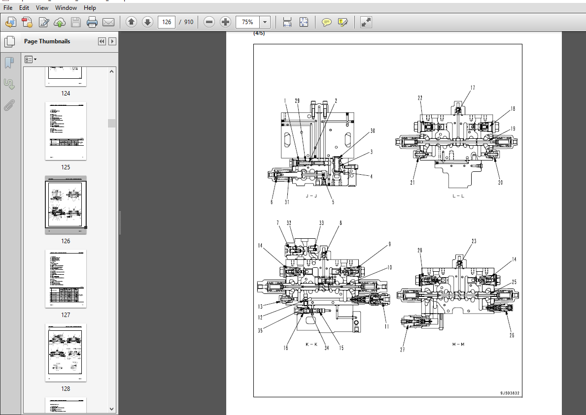
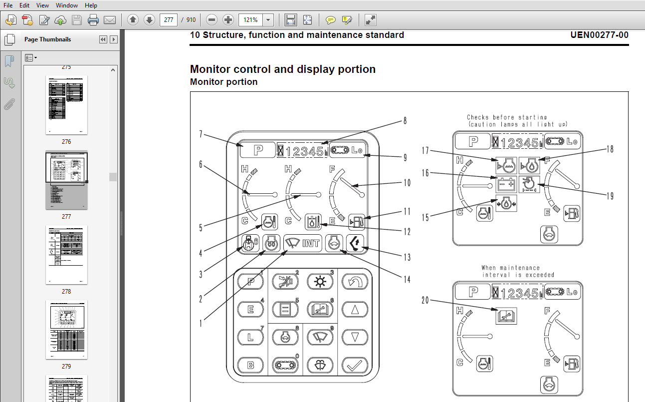
00 Index and foreword............................................................................  3
	Index........................................................................................  3
		Organization list of the shop manual.....................................................  4
		Table of contents........................................................................  6
00 Index and foreword............................................................................ 15
	Foreword and general information............................................................. 15
		Foreword and general information......................................................... 16
			Safety notice........................................................................ 16
			How to read the shop manual.......................................................... 20
			Explanation of terms for maintenance standard........................................ 22
			Handling electric equipment and hydraulic component.................................. 24
			How to read electric wire code....................................................... 32
			Method of disassembling and connecting push-pull type coupler........................ 35
			Standard tightening torque table..................................................... 38
			Conversion table..................................................................... 42
01 Specification................................................................................. 49
	Specification and technical data............................................................. 49
		Specification and technical data......................................................... 50
			Specification dimension drawings..................................................... 50
			Specifications....................................................................... 52
			Weight table......................................................................... 55
			Table of fuel, coolant and lubricants................................................ 56
10 Structure, function and maintenance standard.................................................. 59
	Engine and cooling system.................................................................... 59
		Engine and cooling system................................................................ 60
			Engine related parts................................................................. 60
			Radiator, oil cooler and aftercooler................................................. 61
10 Structure, function and maintenance standard.................................................. 63
	Power train.................................................................................. 63
		Power train.............................................................................. 64
			Power train.......................................................................... 64
			Final drive.......................................................................... 66
			Sprocket............................................................................. 68
			Swing machinery...................................................................... 70
			Swing circle......................................................................... 72
10 Structure, function and maintenance standard.................................................. 75
	Undercarriage and frame...................................................................... 75
		Undercarriage and frame.................................................................. 76
			Track frame and recoil spring........................................................ 76
			Idler................................................................................ 78
			Carrier roller....................................................................... 80
			Track roller......................................................................... 81
			Track shoe........................................................................... 82
10 Structure, function and maintenance standard.................................................. 87
	Hydraulic system, Part 1..................................................................... 87
		Hydraulic system, Part 1................................................................. 88
			Hydraulic equipment layout drawing................................................... 88
			Hydraulic tank and filter............................................................ 90
			Hydraulic pump....................................................................... 92
10 Structure, function and maintenance standard..................................................117
	Hydraulic system, Part 2.....................................................................117
		Hydraulic system, Part 2.................................................................118
			Control valve........................................................................118
			CLSS.................................................................................130
			Functions and operation by valve.....................................................134
			Merge-divider valve..................................................................149
			Attachment circuit selector valve....................................................168
			Hydraulic drift prevention valve.....................................................170
10 Structure, function and maintenance standard..................................................177
	Hydraulic system, Part 3.....................................................................177
		Hydraulic system, Part 3.................................................................178
			Valve control........................................................................178
			PPC valve............................................................................180
			Solenoid valve.......................................................................196
			PPC accumulator......................................................................198
			Return oil filter....................................................................199
			Center swivel joint..................................................................200
			Travel motor.........................................................................201
			Swing motor..........................................................................213
			Hydraulic cylinder...................................................................222
10 Structure, function and maintenance standard..................................................225
	Work equipment...............................................................................225
		Work equipment...........................................................................226
			Work equipment.......................................................................226
			Dimensions of components.............................................................228
10 Structure, function and maintenance standard..................................................233
	Cab and its attachments......................................................................233
		Cab and its attachments..................................................................234
			Air conditioner piping...............................................................234
10 Structure, function and maintenance standard..................................................237
	Electrical system............................................................................237
		Electrical system........................................................................238
			Engine control.......................................................................238
			Electronic control system............................................................247
			Monitor system.......................................................................274
			Sensor...............................................................................292
			KOMTRAX terminal system..............................................................295
20 Standard value table..........................................................................299
	Standard service value table.................................................................299
		Standard service value table.............................................................300
			Standard value table for engine related parts........................................300
			Standard value table for chassis related parts.......................................301
30 Testing and adjusting.........................................................................313
	Testing and adjusting, Part 1................................................................313
		Testing and adjusting, Part 1............................................................315
			Tools for testing, adjusting and troubleshooting.....................................315
			Measuring engine speed...............................................................317
			Measuring air boost pressure.........................................................318
			Measuring exhaust gas color..........................................................319
			Adjusting valve clearance............................................................321
			Measuring compression pressure.......................................................323
			Measuring blow-by pressure...........................................................327
			Measuring engine oil pressure........................................................328
			Measuring fuel pressure..............................................................329
			Handling during cylinder cut-out operation...........................................333
			Handling during no injection cranking operation......................................333
			Measuring fuel return rate and leakage...............................................334
			Bleeding air from fuel circuit.......................................................336
			Checking fuel circuit for leakage....................................................337
			Checking and adjusting air compressor belt tension...................................338
			Measuring clearance in swing circle bearings.........................................339
			Checking and adjusting track shoe tension............................................340
			Checking and adjusting oil pressure in work equipment, swing and travel circuit......341
			Checking and adjusting control circuit oil pressure..................................345
			Checking and adjusting pump PC control circuit oil pressure..........................346
			Checking and adjusting pump LS control circuit oil pressure..........................349
			Measuring solenoid valve output pressure.............................................354
			Measuring PPC valve output pressure..................................................358
			Adjusting play of work equipment and swing PPC valves................................359
			Inspecting locations of hydraulic drift of work equipment............................360
			Releasing remaining pressure in hydraulic circuit....................................362
			Measuring oil leakage amount.........................................................362
			Bleeding air from various parts......................................................365
			Diode inspection procedures..........................................................367
30 Testing and adjusting.........................................................................369
	Testing and adjusting, Part 2................................................................369
		Testing and adjusting, Part 2............................................................370
			Special functions of machine monitor.................................................370
			Handling voltage circuit of engine controller........................................397
			Procedure for turning on KOMTRAX terminal............................................398
			KOMTRAX terminal lamp indications....................................................401
			Preparation work for troubleshooting of electrical system............................404
			Pm clinic service....................................................................407
40 Troubleshooting...............................................................................413
	General information on troubleshooting.......................................................413
		Information related to troubleshooting...................................................414
			Points to remember when troubleshooting..............................................414
			Sequence of events in troubleshooting................................................415
			Checks before troubleshooting........................................................416
			Classification and troubleshooting steps.............................................417
			Connection table for connector pin numbers...........................................421
			T-boxes and T-adapters table.........................................................444
40 Troubleshooting...............................................................................449
	Troubleshooting by failure code (Display of code), Part 1....................................449
		Troubleshooting by failure code (Display of code), Part 1................................451
			Failure codes table..................................................................451
			Before carrying out troubleshooting when failure code is displayed...................454
			Information in troubleshooting table.................................................458
			Failure code [A000N1] Eng. Hi Out of Std.............................................460
			Failure code [AA10NX] Air cleaner Clogging...........................................461
			Failure code [AB00KE] Charge Voltage Low.............................................462
			Failure code [B@BAZG] Eng Oil Press. Low.............................................464
			Failure code [B@BAZK] Eng Oil Level Low..............................................466
			Failure code [B@BCNS] Eng. Water Overheat............................................468
			Failure code [B@BCZK] Eng Water Level Low............................................470
			Failure code [B@HANS] Hydr Oil Overheat..............................................471
			Failure code [CA111] EMC Critical Internal Failure...................................472
			Failure code [CA115] Eng Ne and Bkup Speed Sens Error................................472
			Failure code [CA122] Chg Air Press Sensor High Error.................................474
			Failure code [CA123] Chg Air Press Sensor Low Error..................................476
			Failure code [CA131] Throttle Sensor High Error......................................478
			Failure code [CA132] Throttle Sensor Low Error.......................................480
			Failure code [CA144] Coolant Temp Sens High Error....................................482
			Failure code [CA145] Coolant Temp Sens Low Error.....................................484
			Failure code [CA153] Chg Air Temp Sensor High Error..................................486
			Failure code [CA154] Chg Air Temp Sensor Low Error...................................488
			Failure code [CA187] Sens Supply 2 Volt Low Error....................................490
			Failure code [CA221] Ambient Press Sens High Error...................................492
			Failure code [CA222] Ambient Press Sens Low Error....................................494
			Failure code [CA227] Sens Supply 2 Volt High Error...................................496
			Failure code [CA234] Eng Overspeed...................................................497
			Failure code [CA238] Ne Speed Sens Supply Volt Error.................................498
			Failure code [CA271] IMV/PCV1 Short Error............................................499
			Failure code [CA272] IMV/PCV1 Open Error.............................................500
			Failure code [CA322] Inj #1 Open/Short Error.........................................502
			Failure code [CA323] Inj #5 Open/Short Error.........................................504
			Failure code [CA324] Inj #3 Open/Short Error.........................................506
			Failure code [CA325] Inj #6 Open/Short Error.........................................508
			Failure code [CA331] Inj #2 Open/Short Error.........................................510
			Failure code [CA332] Inj #4 Open/Short Error.........................................512
40 Troubleshooting...............................................................................515
	Troubleshooting by failure code (Display of code), Part 2....................................515
		Troubleshooting by failure code (Display of code), Part 2................................517
			Failure code [CA342] Calibration Code Incompatibility................................517
			Failure code [CA351] Injectors Drive Circuit Error...................................518
			Failure code [CA352] Sens Supply 1 Volt Low Error....................................520
			Failure code [CA386] Sens Supply 1 Volt High Error...................................522
			Failure code [CA428] Water in Fuel Sensor High Error.................................524
			Failure code [CA429] Water in Fuel Sensor Low Error..................................526
			Failure code [CA441] Battery Voltage Low Error.......................................528
			Failure code [CA442] Battery Voltage High Error......................................530
			Failure code [CA449] Rail Press Very High Error......................................532
			Failure code [CA451] Rail Press Sensor High Error....................................536
			Failure code [CA452] Rail Press Sensor Low Error.....................................538
			Failure code [CA553] Rail Press High Error...........................................540
			Failure code [CA559] Rail Press Low Error............................................542
			Failure code [CA689] Eng Ne Speed Sensor Error.......................................544
			Failure code [CA731] Eng Bkup Speed Sens Phase Error.................................546
			Failure code [CA757] All Persistent Data Lost Error..................................548
			Failure code [CA778] Eng Bkup Speed Sensor Error.....................................550
			Failure code [CA1633] KOMNET Datalink Timeout Error..................................552
			Failure code [CA2185] Throt Sens Sup Volt High Error.................................554
			Failure code [CA2186] Throt Sens Sup Volt Low Error..................................555
			Failure code [CA2249] Rail Press Very Low Error......................................556
			Failure code [CA2265] Electric Lift Pump High Error..................................558
			Failure code [CA2266] Electric Lift Pump Low Error...................................560
			Failure code [CA2555] Grid Htr Relay Volt High Error.................................562
			Failure code [CA2556] Grid Htr Relay Volt Low Error..................................564
			Failure code [D110KB] Battery Relay Drive S/C........................................566
			Failure code [D196KA] Service Return Relay Disc......................................568
			Failure code [D196KB] Service Return Relay S/C.......................................570
			Failure code [DA25KP] Press. Sensor Power Abnormality................................572
			Failure code [DA2RMC] Pump Comm. Abnormality.........................................574
			Failure code [DA2SKQ] Model Selection Abnormality....................................576
40 Troubleshooting...............................................................................579
	Troubleshooting by failure code (Display of code), Part 3....................................579
		Troubleshooting by failure code (Display of code), Part 3................................582
			Failure code [DAFRMC] Monitor Comm. Abnormality......................................582
			Failure code [DHPAMA] F Pump Press Sensor Abnormality................................584
			Failure code [DHPBMA] R Pump Press Sensor Abnormality................................586
			Failure code [DHS3MA] Arm Curl PPC Sen. Abnormality..................................588
			Failure code [DHS4MA] Bucket Curl PPC Press Sensor Abnormality.......................590
			Failure code [DW43KA] Travel Speed Sol. Disc.........................................592
			Failure code [DW43KB] Travel Speed Sol. S/C..........................................594
			Failure code [DW45KA] Swing Brake Sol. Disc..........................................597
			Failure code [DW45KB] Swing Brake Sol. S/C...........................................600
			Failure code [DW91KA] Travel Junction Sol. Disc......................................602
			Failure code [DW91KB] Travel Junction Sol. S/C.......................................604
			Failure code [DWJ0KA] Merge-divider Sol. Disc........................................606
			Failure code [DWJ0KB] Merge-divider Sol. S/C.........................................608
			Failure code [DWK0KA] 2-stage Relief Sol. Disc.......................................610
			Failure code [DWK0KB] 2-stage Relief Sol. S/C........................................612
			Failure code [DXA0KA] PC-EPC Sol. Disc...............................................614
			Failure code [DXA0KB] PC-EPC Sol. S/C................................................616
			Failure code [DXE0KA] LS-EPC Sol. Disc...............................................618
			Failure code [DXE0KB] LS-EPC Sol. S/C................................................620
			Failure code [DXE4KA] Service Current EPC Disc.......................................622
			Failure code [DXE4KB] Service Current EPC S/C........................................623
			Failure code [DY20KA] Wiper Working Abnormality......................................624
			Failure code [DY20MA] Wiper Parking Abnormality......................................626
			Failure code [DY2CKB] Washer Drive S/C...............................................628
			Failure code [DY2DKB] Wiper Drive (For) S/C..........................................630
			Failure code [DY2EKB] Wiper Drive (Rev) S/C..........................................632
40 Troubleshooting...............................................................................635
	Troubleshooting of electrical system (E-mode)................................................635
		Troubleshooting of electrical system (E-mode)............................................638
			Before carrying out troubleshooting of electrical system.............................638
			Information contained in troubleshooting table.......................................640
			E-1 Engine does not start............................................................641
			E-2 Auto-decelerator does not operate................................................644
			E-3 Automatic warming-up system does not operate.....................................646
			E-4 Preheater does not operate.......................................................648
			E-5 All work equipment, swing, and travel mechanism do not move......................650
			E-6 Power maximizing function does not operate.......................................652
			E-7 Machine monitor does not display at all..........................................653
			E-8 Machine monitor does not display some items......................................654
			E-9 Contents of display by machine monitor are different from applicable machine.....654
			E-10 Fuel level monitor was lighted in red while engine running......................655
			E-11 Engine coolant temperature gauge does not indicate normally.....................656
			E-12 Hydraulic oil temperature gauge does not indicate normally......................658
			E-13 Fuel level gauge does not indicate normally.....................................659
			E-14 Swing lock monitor does not indicate normally...................................660
			E-15 When monitor switch is operated, monitor displays nothing.......................662
			E-16 Windshield wiper and window washer do not operate...............................664
			E-17 Machine push-up function does not operate normally..............................668
			E-18 Monitoring function fails to display “boom raise” normally......................670
			E-19 Monitoring function fails to display “boom lower” normally......................671
			E-20 Monitoring function fails to display “arm IN” normally..........................672
			E-21 Monitoring function fails to display “arm OUT” normally.........................673
			E-22 Monitoring function fails to display “bucket CURL” normally.....................674
			E-23 Monitoring function fails to display “bucket DUMP” normally.....................675
			E-24 Monitoring function fails to display “swing” normally...........................676
			E-25 Monitoring function fails to display “travel” normally..........................678
			E-26 Monitoring function fails to display “travel differential pressure” normally....680
			E-27 Monitoring function fails to display “service” normally.........................682
			E-28 KOMTRAX system does not operate normally........................................684
			E-29 Air conditioner does not operate................................................686
			E-30 Travel alarm does not sound or does not stop sounding...........................688
			E-31 Horn does not sound.............................................................690
40 Troubleshooting...............................................................................693
	Troubleshooting of hydraulic and mechanical system (H-mode)..................................693
		Troubleshooting of hydraulic and mechanical system (H- mode).............................696
			System chart for hydraulic and mechanical system.....................................696
			Information contained in troubleshooting table.......................................698
			H-1 All work equipment lack power, or travel and swing speeds are slow...............700
			H-2 Engine speed sharply drops or engine stalls......................................702
			H-3 No work equipment, swing or travel move..........................................703
			H-4 Abnormal noise is heard from around hydraulic pump...............................703
			H-5 Auto-decelerator does not work...................................................704
			H-6 Fine control mode does not function or responds slow.............................704
			H-7 Boom moves slowly or lacks power.................................................705
			H-8 Arm moves slowly or lacks power..................................................706
			H-9 Bucket moves slowly or lacks power...............................................707
			H-10 Work equipment does not move in its single operation............................707
			H-11 Work equipment has a bit too fast hydraulic drift...............................708
			H-12 Work equipment has big time lag.................................................710
			H-13 Other work equipment moves when relieving single circuit........................710
			H-14 Power max. switch does not operate..............................................711
			H-15 In compound operation, work equipment with larger load moves slowly.............711
			H-16 In swing + boom RAISE operation, boom moves slowly..............................712
			H-17 In swing + travel operation, travel speed drops sharply.........................712
			H-18 Machine swerves in travel.......................................................713
			H-19 Machine travels slowly..........................................................714
			H-20 Machine cannot be easily steered or lacks power.................................715
			H-21 Travel speed does not shift, or it is too slow or fast..........................716
			H-22 Track shoe does not turn (on one side only).....................................717
			H-23 Machine does not swing..........................................................718
			H-24 Swing acceleration is poor, or swing speed is slow..............................720
			H-25 Excessive overrun when stopping swing...........................................722
			H-26 There is big shock when stopping swing..........................................723
			H-27 Large sound is made when upper structure stops swinging.........................723
			H-28 Swing hydraulic drift is too big................................................724
40 Troubleshooting...............................................................................727
	Troubleshooting of engine (S-mode)...........................................................727
		Troubleshooting of engine (S-mode).......................................................729
			Method of using troubleshooting chart................................................729
			S-1 Starting performance is poor.....................................................732
			S-2 Engine does not start............................................................733
			S-3 Engine does not pick up smoothly.................................................736
			S-4 Engine stops during operations...................................................737
			S-5 Engine does not rotate smoothly..................................................738
			S-6 Engine lacks output (or lacks power).............................................739
			S-7 Exhaust smoke is black (incomplete combustion)...................................740
			S-8 Oil consumption is excessive (or exhaust smoke is blue)..........................741
			S-9 Oil becomes contaminated quickly.................................................742
			S-10 Fuel consumption is excessive...................................................743
			S-11 Oil is in coolant (or coolant spurts back or coolant level goes down)...........744
			S-12 Oil pressure drops..............................................................745
			S-13 Oil level rises (Entry of coolant or fuel)......................................746
			S-14 Coolant temperature becomes too high (overheating)..............................747
			S-15 Abnormal noise is made..........................................................748
			S-16 Vibration is excessive..........................................................749
50 Disassembly and assembly......................................................................751
	General information on disassembly and assembly..............................................751
		General information on disassembly and assembly..........................................752
			How to read this manual..............................................................752
			Coating materials list...............................................................754
			Special tools list...................................................................757
			Sketches of special tools............................................................761
50 Disassembly and assembly......................................................................765
	Engine and cooling system....................................................................765
		Engine and cooling system................................................................766
			Removal and installation of fuel supply pump assembly................................766
			Removal and installation of engine front seal........................................769
			Removal and installation of engine rear seal.........................................771
			Removal and installation of cylinder head assembly...................................776
			Removal and installation of radiator assembly........................................786
			Removal and installation of hydraulic oil cooler assembly............................788
			Removal and installation of aftercooler assembly.....................................790
			Removal and installation of engine and hydraulic pump assembly.......................791
50 Disassembly and assembly......................................................................797
	Power train..................................................................................797
		Power train..............................................................................798
			Removal and installation of final drive assembly.....................................798
			Disassembly and assembly of final drive assembly.....................................799
			Removal and installation of swing motor and swing machinery assembly.................807
			Disassembly and assembly of swing motor and swing machinery assembly.................808
			Removal and installation of swing circle assembly....................................815
50 Disassembly and assembly......................................................................817
	Undercarriage and frame......................................................................817
		Undercarriage and frame..................................................................818
			Disassembly and assembly of carrier roller...........................................818
			Disassembly and assembly of track roller assembly....................................819
			Disassembly and assembly of idler assembly...........................................820
			Disassembly and assembly of recoil spring............................................823
			Removal and installation of sprocket.................................................825
			Expansion and installation of track shoe assembly....................................826
			Removal and installation of revolving frame assembly.................................827
			Removal and installation of counterweight assembly...................................829
50 Disassembly and assembly......................................................................831
	Hydraulic system.............................................................................831
		Hydraulic system.........................................................................832
			Removal and installation of center swivel joint assembly.............................832
			Disassembly and assembly of center swivel joint assembly.............................834
			Removal and installation of hydraulic tank assembly..................................835
			Removal and installation of control valve assembly...................................837
			Disassembly and assembly of control valve assembly...................................840
			Removal and installation of hydraulic pump assembly..................................842
			Removal and installation of oil seal in hydraulic pump input shaft...................845
			Disassembly and assembly of work equipment PPC valve assembly........................846
			Disassembly and assembly of travel PPC valve assembly................................847
			Disassembly and assembly of hydraulic cylinder assembly..............................848
50 Disassembly and assembly......................................................................855
	Work equipment...............................................................................855
		Work equipment...........................................................................856
			Removal and installation of work equipment assembly..................................856
50 Disassembly and assembly......................................................................861
	Cab and its attachments......................................................................861
		Cab and its attachments..................................................................862
			Removal and installation of operator's cab assembly..................................862
			Removal and installation of operator’s cab glass (stuck glass).......................864
			Removal and installation of front window assembly....................................873
50 Disassembly and assembly......................................................................881
	Electrical system............................................................................881
		Electrical system........................................................................882
			Removal and installation of work equipment assembly..................................882
			Removal and installation of machine monitor..........................................884
			Removal and installation of pump controller..........................................884
			Removal and installation of KOMTRAX terminal.........................................885
			Removal and installation of engine controller........................................885
90 Diagrams and drawings.........................................................................887
	Hydraulic diagrams and drawings..............................................................887
90 Diagrams and drawings.........................................................................895
	Electrical diagrams and drawings.............................................................895
IMAGES PREVIEW OF THE MANUAL:
More products