$46
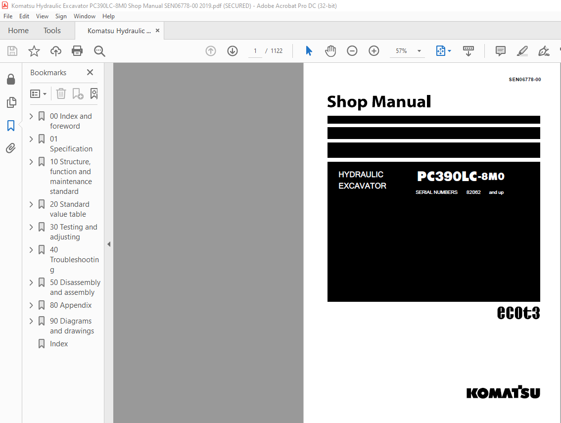
Komatsu PC390LC-8M0 Hydraulic Excavator Shop Manual SEN06778-00 – PDF DOWNLOAD
Komatsu PC390LC-8M0 Hydraulic Excavator Shop Manual SEN06778-00 – PDF DOWNLOAD
FILE DETAILS:
Komatsu PC390LC-8M0 Hydraulic Excavator Shop Manual SEN06778-00 – PDF DOWNLOAD
Language : English
Pages : 1122
Downloadable : Yes
File Type : PDF
Size: 77.5 MB
DESCRIPTION:
Komatsu PC390LC-8M0 Hydraulic Excavator Shop Manual SEN06778-00 – PDF DOWNLOAD
SERIAL NUMBERS 82062 and up
Foreword, safety and general information
Important safety notice
• Appropriate servicing and repair are extremely important to ensure safe operation of the machine. The
shop manual describes the effective and safe servicing and repair methods recommended by Komatsu.
Some of these methods require the use of the special tools designed by Komatsu for the specific purpose.
• The symbol markkis used for such matters that require special cautions during the work. The work
indicated by the caution mark should be performed according to the instructions with special attention to
the cautions. Should hazardous situation occur or be anticipated during such work, be sure to keep safe
first and take every necessary measure.
Safety points
• Good arrangement
• Correct work clothes
• Observance of work standard
• Practice of making and checking signals
• Prohibition of operation and handling by
unlicensed workers
• Safety check before starting work
• Wearing protective goggles (for cleaning or
grinding work)
• Wearing shielding goggles and protectors (for
welding work)
• Good physical condition and preparation
• Precautions against work which you are not used to or you are used to too much
General precautions:
• Before performing any greasing or repairs, read all the safety labels stuck to the machine. For the locations of the safety labels and detailed explanation of precautions, see the operation and maintenance manual.• Locate a place in the repair workshop to keep the tools and removed parts. Always keep the tools and parts in their correct places. Always keep the work area clean and make sure that there is no dirt, water or oil on the floor. Smoke only in the areas provided for smoking. Never smoke while working.• When performing any work, always wear the safety shoes and helmet. Do not wear loose work cloths, or clothes with buttons missing. 1. Always wear the protective eyeglasses when hitting parts with a hammer.Always wear the protective eyeglasses when grinding parts with a grinder, etc.• When performing any work with 2 or more workers, always agree on the working procedure before starting. While working, always keep conversations of the work between your fellow workers and your self on any step of the work. During the work, hang the warning tag of “UNDER WORKING” in the operator’s compartment.• Only qualified workers must perform the work and operation which require license or qualification.• Keep the tools in good condition. And learn the correct way to use the tools, and use the proper ones among them. Before starting the work, thoroughly check the tools, lift truck, service vehicle, etc.• If welding repairs is required, always have a trained and experienced welder with good knowledge of welding perform the work. When performing welding work, always wear welding gloves, apron, shielding goggles, cap, etc.• Before starting work, warm up your body thoroughly to start work under good condition.• Avoid continuing work for long hours and take rests with proper intervals to keep your body in good condition. Take a rest in a specified safe place.
How to read the shop manual :
• Some attachments and optional parts described in this shop manual may not be arranged for certain
areas. Contact your Komatsu distributor if one or some of them are required.
• Materials and specifications are subject to change without notice.
• The shop manuals are available for “Machine part” and “Engine part”. For the engine, see the shop
manual for the same model of the engine as the one which is mounted on the machine.
Composition of shop manual
• This shop manual describes the technical information required for the services performed in a workshop.
The shop manual is divided into the following chapters for the convenience of use.
00. Index and foreword
• This section includes the index, foreword, safety and basic information.
01. Specification
• This section explains the specifications of the machine.
10. Structure and function
• This section explains the structure and function of the machine. The section of “Structure and function”
serves not only to give an understanding for the structure of each component, but also serves as
reference material for troubleshooting.
20. Standard value table
• The standard values for a new machine and trouble shooting are indicated. This standard value table is
used for testing and adjusting, and determining a failure at troubleshooting.
30. Testing and adjusting
• This section describes the measuring tools and how to measure, and how to adjust various parts. As for
the standard value and failure criterion, see the standard value table.
40. Troubleshooting
• This section describes the troubleshooting in a suspected area when a failure occurs and the remedy for
the failure. Troubleshooting is described by each failure mode.
50. Disassembly and assembly
• This section explains the procedures for removing, installing, disassembling, and assembling each part or
component and the special tools for the works as well as precautions for doing them safely. In addition,
tightening torque, and quantity and weight of coating material, oil, grease, and coolant required for the
works are also explained.
60. Maintenance standard
• This section describes the maintenance standard values for each component. This section gives the
criterion values for each component and required remedy at disassembly or maintenance.
80. Appendix
• The structure and function, testing and adjusting, and troubleshooting for all of the other components or
equipment which can not be separately classified are explained together in the appendix.
90. Diagrams and drawings
• This section gives hydraulic circuit diagrams and electrical circuit diagrams.
TABLE OF CONTENTS:
Komatsu PC390LC-8M0 Hydraulic Excavator Shop Manual SEN06778-00 – PDF DOWNLOAD
00 Index and foreword 3
Table of contents 4
Foreword and general information 13
Foreword, safety and general information 13
How to read the shop manual 20
Explanation of terms for maintenance standard 22
Handling equipment of fuel system devices 24
Handling of intake system parts 25
Handling of hydraulic equipment 26
Method of disconnecting and connectingof push-pull type coupler 28
Handling of electrical equipment 31
How to read electric wire code 40
Precautions when performing operation 43
Practical use of KOMTRAX 46
Standard tightening torque table 47
List of abbreviation 51
Conversion table 56
01 Specification 61
Specification and technical data 63
Specification dimension drawings 63
Specifications 65
Weight table 68
Table of fuel, coolant and lubricants 69
10 Structure, function and maintenance standard 71
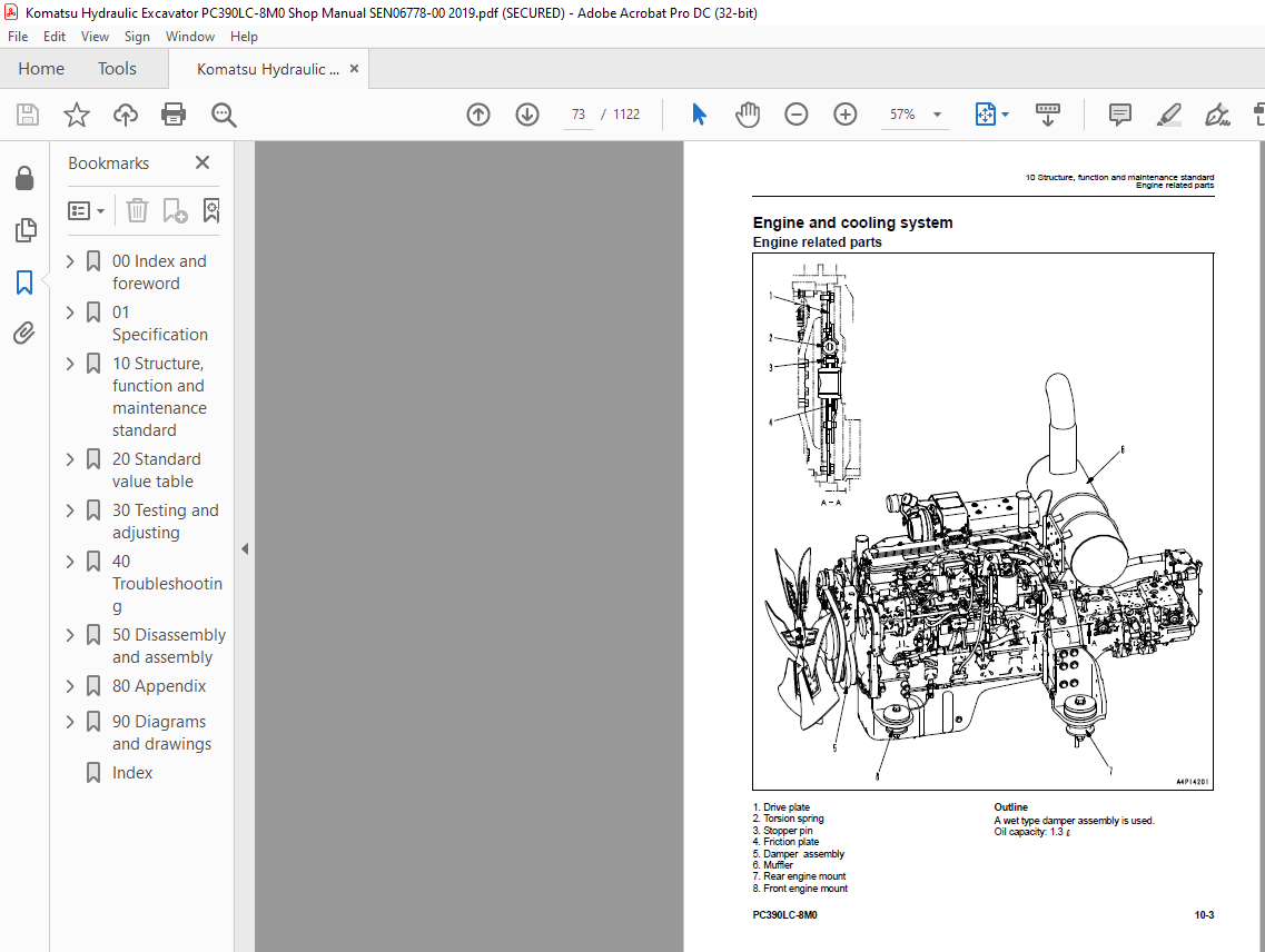
Engine and cooling system 73
Engine related parts 73
Radiator, oil cooler and aftercooler 74
Power train 75
Power train 75
Swing circle 76
Swing machinery 78
Final drive 80
Sprocket 82
Undercarriage and frame 84
Track frame and recoil spring 84
Idler 86
Carrier roller 88
Track roller 89
Track shoe 90
Hydraulic system 94
Hydraulic equipment layout drawing 94
Hydraulic tank and filter 96
Hydraulic pump 98
Control valve 122
CLSS 134
Functions and operation by valve 138
Attachment circuit selector valve 177
Hydraulic drift prevention valve 180
Valve control 186
PPC valve 187
Solenoid valve 206
PPC accumulator 208
Center swivel joint 209
Travel motor 211
Swing motor 223
Work equipment cylinder 231
Work equipment 234
Work equipment 234
Dimensions of components 236
Electrical system 240
Engine control system 240
Electronic control system 249
Machine monitor system 274
Sensor 294
KOMTRAX system 297
20 Standard value table 305
Standard service value table 307
Standard value table for engine related parts 307
Standard value table for chassis related parts 308
30 Testing and adjusting 319
Related information on testing and adjusting 321
Tools for testing, adjusting and troubleshooting 321
Sketches of special tools 325
Engine and cooling system 326
Testing engine speed 326
Testing air boost pressure 327
Testing exhaust gas color 328
Adjusting valve clearance 330
Testing compression pressure 332
Testing blowby pressure 336
Testing engine oil pressure 337
Testing fuel pressure 338
Handling during cylinder cutout operation 343
Handling during no-injection cranking operation 343
Testing fuel return rate and leakage 344
Bleeding air from fuel circuit 346
Checking fuel circuit for leakage 347
Testing and adjusting air compressor belt tension 348
Replacing fan belt 349
Replacing alternator belt 350
Power train 351
Testing clearance in swing circle bearings 351
Undercarriage and frame 352
Testing and adjusting track tension 352
Hydraulic system 353
Testing and adjusting oil pressure in work equipment, swing and travel circuit 353
Testing control circuit oil pressure 357
Testing and adjusting pump PC control circuit oil pressure 358
Testing and adjusting pump LS control circuit oil pressure 361
Testing solenoid valve output pressure 366
Testing PPC valve output pressure 370
Adjusting play of work equipment and swing PPC valves 371
Inspecting locations of hydraulic drift of work equipment 372
Releasing remaining pressure in hydraulic circuit 374
Testing oil leakage amount 375
Bleeding air from various parts 377
Testing and charging accumulator (manufactured by NOK) nitrogen gas pressure for attachment (low pressure side) 379
Testing and charging accumulator nitrogen gas pressure for attachment (high pressure side) 381
Replacing accumulator bladder on high pressure side for accumulator piping 383
Electrical sysytem 388
Special functions of machine monitor 388
Handling voltage circuit of engine controller 439
Preparation work for troubleshooting of electrical system 440
Procedure for testing diodes 444
Pm clinic 445
Pm clinic service 445
40 Troubleshooting 453
General Information on troubleshooting 459
Symptom and troubleshooting numbers 459
Sequence of events in troubleshooting 461
Checks before troubleshooting 463
Classification and procedures for troubleshooting 465
Symptom and troubleshooting numbers 467
Information in troubleshooting table 469
Connector list and layout 471
Connection table for connector pin numbers 482
T- branch box and T- branch adapter table 518
Troubleshooting method for open circuit in wiring harness of pressure sensor system 521
Failure codes table 523
Fuse locations 529
Troubleshooting by failure code 531
Failure code [879AKA] A/C Inner Sensor Open Circuit 531
Failure code [879AKB] A/C Inner Sensor Short Circuit 531
Failure code [879BKA] A/C Outer Sensor Open Circuit 531
Failure code [879BKB] A/C Outer Sensor Short Circuit 531
Failure code [879CKA] Ventilating Sensor Open Circuit 531
Failure code [879CKB] Ventilating Sensor Short Circuit 532
Failure code [879DKZ] Sunlight Sensor Open Or Short Circuit 532
Failure code [879EMC] Ventilation Damper Abnormality 532
Failure code [879FMC] Air Mix Damper Abnormality 532
Failure code [879GKX] Refrigerant Abnormality 532
Failure code [989L00] Engine Controller Lock Caution1 533
Failure code [989M00] Engine Controller Lock Caution2 534
Failure code [989N00] Engine Controller Lock Caution3 535
Failure code [AA10NX] Air Cleaner Clogging 536
Failure code [AB00KE] Charge Voltage Low 538
Failure code [B@BAZG] Eng Oil Press Low 540
Failure code [B@BAZK] Engine Oil Level Low 541
Failure code [B@BCNS] Eng Water Overheat 542
Failure code [B@BCZK] Radiator Coolant Level Low 544
Failure code [B@HANS] Hyd Oil Overheat 546
Failure code [CA111] ECM Critical Internal Failure 547
Failure code [CA115] Eng Ne and Bkup Speed Sens Error 547
Failure code [CA122] Chg Air Press Sensor High Error 548
Failure code [CA123] Chg Air Press Sensor Low Error 550
Failure code [CA131] Throttle Sensor High Error 552
Failure code [CA132] Throttle Sensor Low Error 554
Failure code [CA144] Coolant Temp Sens High Error 556
Failure code [CA145] Coolant Temp Sens Low Error 558
Failure code [CA153] Chg Air Temp Sensor High Error 560
Failure code [CA154] Chg Air Temp Sensor Low Error 562
Failure code [CA155] Chg Air Temp High Speed Derate 564
Failure code [CA187] Sens Supply 2 Volt Low Error 566
Failure code [CA221] Ambient Press Sens High Error 568
Failure code [CA222] Ambient Press Sens Low Error 570
Failure code [CA227] Sens 2 Supply Volt High Error 572
Failure code [CA234] Eng Overspeed 572
Failure code [CA238] Ne Speed Sens Supply Volt Error 573
Failure code [CA271] IMV/PCV1 Short Error 574
Failure code [CA272] IMV/PCV1 Open Error 576
Failure code [CA281] Abnormal supply pump pressure balance 578
Failure code [CA322] Inj #1(L#1) Open/Short Error 580
Failure code [CA323] Inj #5(L#5) Open/Short Error 582
Failure code [CA324] Inj #3(L#3) Open/Short Error 584
Failure code [CA325] Inj #6(L#6) Open/Short Error 586
Failure code [CA331] Inj #2(L#2) Open/Short Error 588
Failure code [CA332] Inj #4(L#4) Open/Short Error 590
Failure code [CA342] Calibration Code Incompatibility 592
Failure code [CA351] Injectors Drive Circuit Error 593
Failure code [CA352] Sens Supply 1 Volt Low Error 594
Failure code [CA386] Sens Supply 1 Volt High Error 596
Failure code [CA428] Water in Fuel Sensor High Error 598
Failure code [CA429] Water in Fuel Sensor Low Error 600
Failure code [CA435] Eng Oil Press Sw Error 602
Failure code [CA441] Battery Voltage Low Error 604
Failure code [CA442] Battery Voltage High Error 606
Failure code [CA449] Rail Press Very High Error 607
Failure code [CA451] Rail Press Sensor High Error 608
Failure code [CA452] Rail Press Sensor Low Error 610
Failure code [CA488] Chg Air Temp High Torque Derate 612
Failure code [CA553] Rail Press High Error 613
Failure code [CA559] Rail Press Low Error 614
Failure code [CA689] Eng Ne Speed Sensor Error 616
Failure code [CA731] Eng Bkup Speed Sens Phase Error 620
Failure code [CA757] All Continuous Data Lost Error 621
Failure code [CA778] Eng Bkup Speed Sensor Error 622
Failure code [CA2185] Throt Sens Sup Volt High Error 625
Failure code [CA2186] Throt Sens Sup Volt Low Error 626
Failure code [CA2249] Rail Press Very Low Error 627
Failure code [CA2265] Fuel Feed Pump Open Error 628
Failure code [CA2266] Fuel Feed Pump Short Error 630
Failure code [CA2311] lMV Solenoid Error 631
Failure code [CA2555] Grid Htr Relay Open Circuit Error 632
Failure code [CA2556] Grid Htr Relay Short Circuit Error 634
Failure code [D110KB] Battery Relay Drive Short Circuit 636
Failure code [D19JKZ] Personal Code Relay Abnormality 638
Failure code [D811MC] KOMTRAX Error 640
Failure code [D862KA] GPS Antenna Open Circuit 641
Failure code [D8AQKR] CAN2 Discon (KOMTRAX) 642
Failure code [DA22KK] Pump Solenoid Power Low Error 644
Failure code [DA25KP] 5V Sensor 1 Power Abnormality 646
Failure code [DA26KP] 5V Sensor 2 Power Abnormality 648
Failure code [DA29KQ] Model Selection Abnormality 650
Failure code [DA2QKR] CAN2 Discon (Pump Con) 652
Failure code [DAF0MB] Monitor ROM Abnormality 655
Failure code [DAF0MC] Monitor Error 656
Failure code [DAF8KB] Camera Power Supply Short Circuit 658
Failure code [DAF9KQ] Model Selection Abnormality 660
Failure code [DAFGMC] GPS Module Error 661
Failure code [DAFQKR] CAN2 Discon 662
Failure code [DAZ9KQ] A/C Model Selection Abnormality 663
Failure code [DAZQKR] CAN2 Discon (Aircon ECU) 664
Failure code [DB2QKR] CAN2 Discon (Engine Con) 666
Failure code [DGH2KB] Hyd Oil Sensor Short Circuit 670
Failure code [DHA4KA] Air Cleaner Clog Sensor Open Circuit 672
Failure code [DHPAMA] F Pump Press Sensor Abnormality 674
Failure code [DHPBMA] R Pump Press Sensor Abnormality 676
Failure code [DHS3MA] Arm Curl PPC Press Sensor Abnormality 678
Failure code [DHS4MA] Bucket CURL PPC Press Sensor Abnormality 680
Failure code [DHS8MA] Boom Raise PPC Press Sensor Abnormality 682
Failure code [DHS9MA] Boom Lower PPC Press Sensor Abnormality 684
Failure code [DHSAMA] Swing RH PPC Press Sensor Abnormality 686
Failure code [DHSBMA] Swing LH PPC Press Sensor Abnormality 688
Failure code [DHSCMA] Arm Dump PPC Press Sensor Abnormality 690
Failure code [DHSDMA] Bucket Dump PPC Press Sensor Abnormality 692
Failure code [DHSFMA] Travel FW L PPC Press Sensor Abnormality 694
Failure code [DHSGMA] Travel FW R PPC Press Sensor Abnormality 696
Failure code [DHSHMA] Travel BW L PPC Press Sensor Abnormality 698
Failure code [DHSJMA] Travel BW R PPC Press Sensor Abnormality 700
Failure code [DHX1MA] Overload Sensor Abnormality 702
Failure code [DR21KX] Camera 2 Picture Rev Drive Abnormality 704
Failure code [DR31KX] Camera 3 Picture Rev Drive Abnormality 706
Failure code [DV20KB] Travel Alarm Short Circuit 708
Failure code [DW43KA] Travel Speed Sol Open Circuit 710
Failure code [DW43KB] Travel Speed Sol Short Circuit 712
Failure code [DW45KA] Swing Brake Sol Valve Open Circuit 714
Failure code [DW45KB] Swing Brake Sol Short Circuit 716
Failure code [DW91KA] Travel Neutral Sol Open Circuit 718
Failure code [DW91KB] Travel Neutral Sol Short Circuit 720
Failure code [DWA2KA] Attachment Sol Open Circuit 722
Failure code [DWA2KB] Attachment Sol Short Circuit 724
Failure code [DWJ0KA] Merge-divider Sol Open Circuit 726
Failure code [DWJ0KB] Merge-divider Sol Short Circuit 728
Failure code [DWK0KA] 2-stage Relief Sol Open Circuit 730
Failure code [DWK0KB] 2-stage Relief Sol Short Circuit 732
Failure code [DWK2KA] Variable Back Press Sol Open Circuit 734
Failure code [DWK2KB] Variable Back Press Sol Short Circuit 736
Failure code [DXA8KA] PC-EPC Sol Open Circuit 738
Failure code [DXA8KB] PC-EPC Sol Short Circuit 740
Failure code [DXE0KA] LS-EPC Sol Open Circuit 742
Failure code [DXE0KB] LS-EPC Sol Short Circuit 744
Failure code [DXE4KA] Attachment Flow EPC Open Circuit 746
Failure code [DXE4KB] Attachment Flow EPC Short Circuit 748
Failure code [DY20KA] Wiper Working Abnormality 750
Failure code [DY20MA] Wiper Parking Abnormality 752
Failure code [DY2CKB] Washer Drive Short Circuit 754
Failure code [DY2DKB] Wiper Drive (Fwd) Short 756
Failure code [DY2EKB] Wiper Drive (Rev) Short 758
Troubleshooting of electrical system (E-mode) 760
Fuse locations 760
Information contained in troubleshooting table 762
E-1 Engine does not start (Engine does not crank) 764
E-2 Preheater does not operate 769
E-3 When starting switch is turned to ON position, machine monitor displays nothing 773
E-4 When starting switch is turned to ON position (with engine stopped), basic check monitor lights up 776
E-5 Precaution monitor lights up while engine is running 777
E-6 Emergency stop monitor lights up while engine is running 779
E-7 Fuel level gauge does not indicate properly 780
E-8 Engine coolant temperature gauge does not indicate properly 782
E-9 Hydraulic oil temperature gauge does not indicate properly 783
E-10 Displays on machine monitor are different from those for actual machine 786
E-11 Some areas of machine monitor screen are not displayed 787
E-12 Function switch does not operate 787
E-13 Automatic warm-up system does not operate (in cold season) 788
E-14 Auto-decelerator does not operate properly 789
E-15 Working mode does not change 790
E-16 Travel speed does not change 791
E-17 Alarm buzzer cannot be canceled 792
E-18 When starting switch is turned OFF, service meter is not displayed 792
E-19 Service mode cannot be selected 792
E-20 Any of work equipment, swing and travel do not operate or cannot be locked 793
E-21 Swing holding brake does not operate properly 795
E-22 One-touch power maximizing function does not operate properly 798
E-23 Travel alarm does not sound or does not stop sounding 801
E-24 Horn does not sound or does not stop 802
E-25 Windshield wiper and window washer do not operate 804
E-26 Machine push-up function cannot be canceled 806
E-27 Machine push-up function does not operate 808
E-28 BOOM DOWN indicator is not displayed properly with monitoring function 809
E-29 ARM DUMP indicator is not displayed properly with monitoring function 809
E-30 ARM IN indicator is not displayed properly with monitoring function 809
E-31 BOOM RAISE indicator is not displayed properly with monitoring function 810
E-32 BUCKET CURL indicator is not displayed properly with monitoring function 810
E-33 BUCKET DUMP indicator is not displayed properly with monitoring function 810
E-34 SWING indicator is not displayed properly with monitoring function 811
E-35 TRAVEL indicator is not displayed properly with monitoring function 811
E-36 ATTACHMENT indicator is not displayed properly with monitoring function 812
E-37 Attachment hydraulic circuit cannot be changed 814
E-38 KOMTRAX system does not operate properly 815
Troubleshooting of hydraulic and mechanical system (H-mode) 816
System chart for hydraulic and mechanical system 816
Information contained in troubleshooting table 818
H-1 All work equipment lack power, or travel and swing speeds are slow 820
H-2 Engine speed sharply drops or engine stalls 822
H-3 No work equipment, swing or travel move 823
H-4 Abnormal noise is heard from around hydraulic pump 823
H-5 Auto-decelerator does not work 824
H-6 Fine control mode does not function or responds slow 824
H-7 Boom moves slowly or lacks power 825
H-8 Arm moves slowly or lacks power 826
H-9 Bucket moves slowly or lacks power 827
H-10 Work equipment does not move in its single operation 827
H-11 Work equipment has a bit too fast hydraulic drift 828
H-12 Work equipment has big time lag 830
H-13 Other work equipment moves when relieving single circuit 830
H-14 Power max switch does not operate 831
H-15 In compound operation, work equipment with larger load moves slowly 831
H-16 In swing + boom RAISE operation, boom moves slowly 832
H-17 In swing + travel operation, travel speed drops sharply 832
H-18 Machine swerves in travel 833
H-19 Machine travels slowly 834
H-20 Machine cannot be easily steered or lacks power 835
H-21 Travel speed does not shift, or it is too slow or fast 836
H-22 Track shoe does not turn (on one side only) 837
H-23 Machine does not swing 838
H-24 Swing acceleration is poor, or swing speed is slow 840
H-25 Excessive overrun when stopping swing 842
H-26 There is big shock when stopping swing 843
H-27 Large sound is made when upper structure stops swinging 843
H-28 Swing hydraulic drift is too big 844
Troubleshooting of engine (S-mode) 845
Method of using troubleshooting charts 845
S-1 Starting performance is poor 848
S-2 Engine does not start 849
S-3 Engine does not pick up smoothly 852
S-4 Engine stops during operations 853
S-5 Engine does not rotate smoothly 854
S-6 Engine lacks output (or lacks power) 855
S-7 Exhaust smoke is black (incomplete combustion) 856
S-8 Oil consumption is excessive (or exhaust smoke is blue) 857
S-9 Oil becomes contaminated quickly 858
S-10 Fuel consumption is excessive 859
S-11 Oil is in coolant (or coolant spurts back, or coolant level goes down) 860
S-12 Oil pressure drops 861
S-13 Oil level rises (water, fuel in oil) 862
S-14 Coolant temperature becomes too high (overheating) 863
S-15 Abnormal noise is made 864
S-16 Vibration is excessive 865
50 Disassembly and assembly 867
Related information on disassembly and assembly 870
How to read this manual 870
Coating materials list 872
Special tools list 876
Sketches of special tools 879
Engine and cooling system 881
Removal and installation of supply pump assembly 881
Removal and installation of engine front oil seal 885
Removal and installation of engine rear oil seal 888
Removal and installation of cylinder head assembly 893
Removal and installation of radiator assembly 907
Removal and installation of hydraulic oil cooler assembly 909
Removal and installation of aftercooler assembly 911
Removal and installation of engine and hydraulic pump assembly 913
Power train system 918
Removal and installation of travel motor and final drive assembly 918
Disassembly and assembly of final drive assembly 919
Removal and installation of swing motor and swing machinery assembly 928
Disassembly and assembly of swing motor and swing machinery assembly 929
Removal and installation of swing circle assembly 937
Undercarriage and frame 938
Disassembly and assembly of carrier roller assembly 938
Disassembly and assembly of track roller assembly 940
Disassembly and assembly of idler assembly 941
Disassembly and assembly of recoil spring assembly 944
Removal and installation of sprocket 946
Expansion and installation of track shoe assembly 947
Removal and installation of revolving frame assembly 949
Removal and installation of counterweight assembly 951
Hydraulic system 954
Removal and installation of center swivel joint assembly 954
Disassembly and assembly of center swivel joint assembly 956
Removal and installation of hydraulic tank assembly 957
Removal and installation of control valve assembly 959
Disassembly and assembly of control valve assembly 962
Removal and installation of hydraulic pump assembly 967
Removal and installation of hydraulic pump input shaft oil seal 970
Disassembly and assembly of work equipment PPC valve assembly 971
Disassembly and assembly of travel PPC valve assembly 973
Disassembly and assembly of work equipment cylinder assembly 975
Work equipment 981
Removal and installation of work equipment assembly 981
Cab and its attachments 984
Removal and installation of operator’s cab assembly 984
Removal and installation of operator’s cab glass (adhered window glass) 987
Removal and installation of front window assembly 996
Removal and installation of floor frame assembly 1002
Electrical system 1006
Removal and installation of air conditioner unit assembly 1006
Removal and installation of KOMTRAX terminal assembly 1011
Removal and installation of machine monitor assembly 1013
Removal and installation of pump controller assembly 1015
Removal and installation of engine controller assembly 1017
80 Appendix 1019
Air conditioner 1021
Precautions for refrigerant 1021
Air conditioner component 1022
Configuration and function of refrigeration cycle 1024
Outline of refrigeration cycle 1025
Air conditioner unit 1027
Air conditioner controller 1033
Compressor 1034
Condenser 1035
Receiver drier 1036
Sensor 1037
Procedure for testing and troubleshooting 1038
Circuit diagram and arrangement of connector pins 1040
System diagram 1042
Parts and connectors layout 1044
Testing air leakage (duct) 1047
Testing with self-diagnosis function 1049
Testing vent (mode) changeover 1051
Testing FRESH/RECIRC air changeover 1052
Testing sunlight sensor 1053
Testing (dual) pressure switch for refrigerant 1054
Testing relays 1055
Troubleshooting chart 1 1056
Troubleshooting chart 2 1058
Information in troubleshooting table 1060
Failure code list related to air conditioner 1061
Failure code [879AKA] A/C Inner sensor Open Circuit 1062
Failure code [879AKB] A/C Inner sensor Short Circuit 1063
Failure code [879BKA] A/C Outer sensor Open Circuit 1064
Failure code [879BKB] A/C Outer sensor Short Circuit 1066
Failure code [879CKA] Ventilating sensor Open Circuit 1068
Failure code [879CKB] Ventilating sensor Short Circuit 1069
Failure code [879DKZ] Sunlight sensor Open or Short Circuit 1070
Failure code [879EMC] Ventilating Damper Abnormality 1072
Failure code [879FMC] Air Mix Damper Abnormality 1073
Failure code [879GKX] Refrigerant Abnormality 1074
Troubleshooting for power supply and CAN communication system (Air conditioner does not operate) 1076
Troubleshooting for compressor and refrigerant system (Air is not cooled) 1078
Troubleshooting for blower motor system (No air comes out or air flow is abnormal) 1081
Troubleshooting for FRESH/RECIRC air changeover 1083
Troubleshooting with gauge pressure 1085
Connection of service tool 1087
Precautions for disconnecting and connecting air conditioner piping 1089
Handling of compressor oil 1091
90 Diagrams and drawings 1093
Hydraulic diagrams and drawings 1095
Symbols in hydraulic circuit diagram 1095
Hydraulic circuit diagram 1099
Electrical diagrams and drawings 1101
Symbols in electric circuit diagram 1101
Electrical circuit diagram 1105
Index 1115
IMAGES PREVIEW OF THE MANUAL:
More products