$40
Komatsu PC4000-6 Hydraulic Mining Service Manual – PDF DOWNLOAD
Komatsu PC4000-6 Hydraulic Mining Service Manual – PDF DOWNLOAD
FILE DETAILS:
Komatsu PC4000-6 Hydraulic Mining Service Manual – PDF DOWNLOAD
Language : English
Pages : 800
Downloadable : Yes
File Type : PDF
Size: 23.9 MB
IMAGES PREVIEW OF THE MANUAL:
DESCRIPTION:
Komatsu PC4000-6 Hydraulic Mining Service Manual – PDF DOWNLOAD
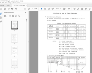
MACHINE MODEL SERIAL NUMBER
PC4000-6 Diesel 08175 /78 /79 /83 /84
The Komatsu PC4000-6 Hydraulic Mining Service Manual provides detailed information on the maintenance and repair of the PC4000-6 hydraulic mining shovel. The manual is intended for use by experienced technicians who have the necessary knowledge and skills to perform the procedures described in the manual.
- The manual covers various topics such as safety information, maintenance procedures, and troubleshooting tips. It provides detailed information on the machine’s systems and components, such as the engine, hydraulic system, electrical system, and undercarriage components. The manual also includes a list of recommended tools and spare parts, as well as detailed specifications for the machine.
- The manual provides step-by-step instructions for maintenance procedures, along with diagrams and illustrations to help technicians understand the procedures. It also provides information on how to diagnose problems, as well as how to perform maintenance and repairs to correct those problems. By following the procedures in the manual, technicians can ensure that the mining shovel is maintained properly and is operating safely and efficiently.
- It is important to follow the instructions and procedures outlined in the manual to ensure the safe and proper maintenance of the mining shovel. The manual provides information on how to perform routine maintenance, as well as how to perform repairs to correct any problems that may arise. By following the procedures in the manual, technicians can ensure that the mining shovel is operating safely and efficiently, and that it will provide reliable performance for many years to come.
- In summary, the Komatsu PC4000-6 Hydraulic Mining Service Manual provides valuable information for the maintenance and repair of the PC4000-6 hydraulic mining shovel. The manual is essential for experienced technicians who are responsible for maintaining and repairing the machine. By following the procedures in the manual, technicians can ensure that the mining shovel is maintained properly and is operating safely and efficiently.
TABLE OF CONTENTS:
Komatsu PC4000-6 Hydraulic Mining Service Manual – PDF DOWNLOAD
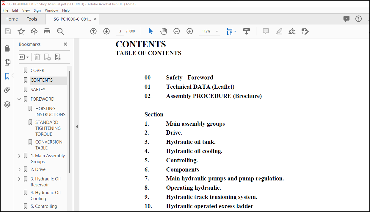
COVER……………………………………………………….. 1
CONTENTS…………………………………………………….. 3
SAFTEY………………………………………………………. 5
FOREWORD…………………………………………………….. 9
HOISTING INSTRUCTIONS……………………………………… 10
STANDARD TIGHTENING TORQUE…………………………………. 12
CONVERSION TABLE………………………………………….. 13
1. Main Assembly Groups……………………………………….. 21
1.0 General lay out……………………………………….. 23
1.1 Superstructure…………………………………….. 25
1.1.1 Machine house………………………………… 27
1.1.2 Hydraulic Oil Reservoir……………………….. 29
1.1.3 Hydraulic Oil Cooler………………………….. 31
1.1.4 Fuel tank (Fuel reservoir)…………………….. 33
1.1.5 Counter weight……………………………….. 35
1.1.6 Cab support………………………………….. 37
1.1.7 Operators cab………………………………… 39
1.1.8 Control blocks……………………………….. 41
1.1.9 Swing gears………………………………….. 43
1.2 Under carriage…………………………………….. 45
1.3 Attachment………………………………………… 47
1.3.1 Backhoe attachment (BHA)………………………. 47
1.3.2 Front Shovel Attachment (FSA)………………….. 49
2. Drive…………………………………………………….. 51
2.0 Prime drive assembly…………………………………… 53
2.1 Engine and PTO mounts………………………………. 55
2.2 Coupling………………………………………….. 59
2.3 Air Filter………………………………………… 61
2.4 Fan drive and radiator assembly……………………… 63
2.5 Radiator fan drive speed adjustment………………….. 67
2.6 Pump distributor gearbox (PTO)………………………. 71
2.7 Pump-spline lubrication…………………………….. 73
2.8 PTO Lubrication and cooling…………………………. 75
2.9 Hydraulic pumps – location, drive speed and flow rates…. 79
3. Hydraulic Oil Reservoir…………………………………….. 81
3.0 General lay out……………………………………….. 83
3.1 Main oil tank, location of switches, sensors etc………. 85
3.2 Suction oil tank with strainers……………………… 87
3.3 Return oil collector tube with strainer………………. 89
3.4 Back pressure valve………………………………… 91
3.5 Transfer pump (Optional Equipment)…………………… 93
3.6 Return and Leak Oil Filter………………………….. 95
3.7 Breather filter……………………………………. 97
4. Hydraulic Oil Cooling………………………………………. 99
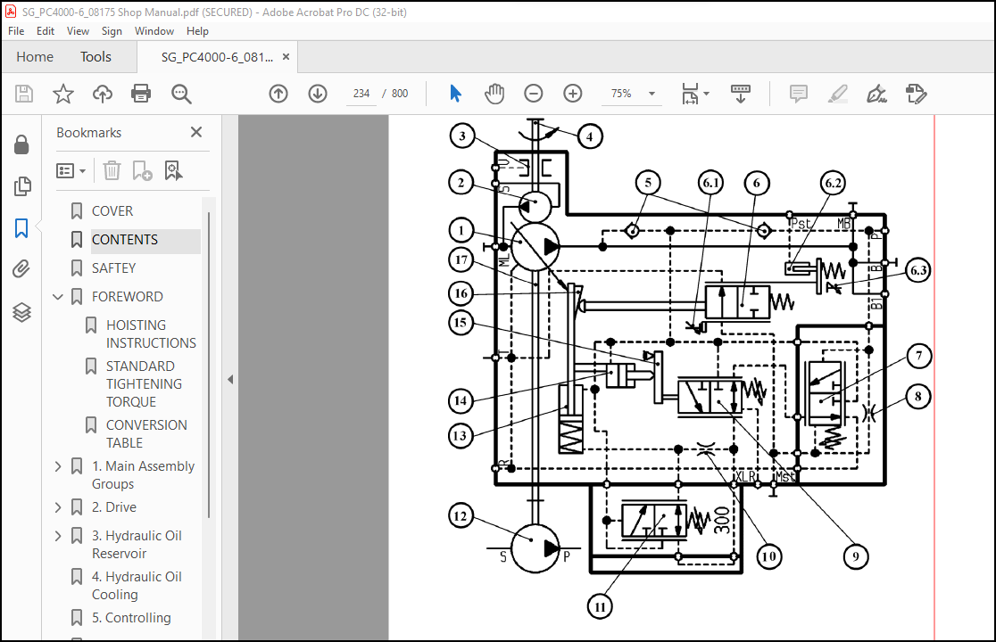
5. Controlling………………………………………………..121
6. Components…………………………………………………169
7. Main Hydraulic Pumps and Pump Regulation System………………..217
15. Lubrication Systems………………………………………..704
More products