$39
Komatsu PC500LC-8 Hydraulic Excavator Shop Manual SEN06648-02 – PDF DOWNLOAD
Komatsu PC500LC-8 Hydraulic Excavator Shop Manual SEN06648-02 – PDF DOWNLOAD
FILE DETAILS:
Komatsu PC500LC-8 Hydraulic Excavator Shop Manual SEN06648-02 – PDF DOWNLOAD
Language : English
Pages : 968
Downloadable : Yes
File Type : PDF
Size: 76.2 MB
DESCRIPTION:
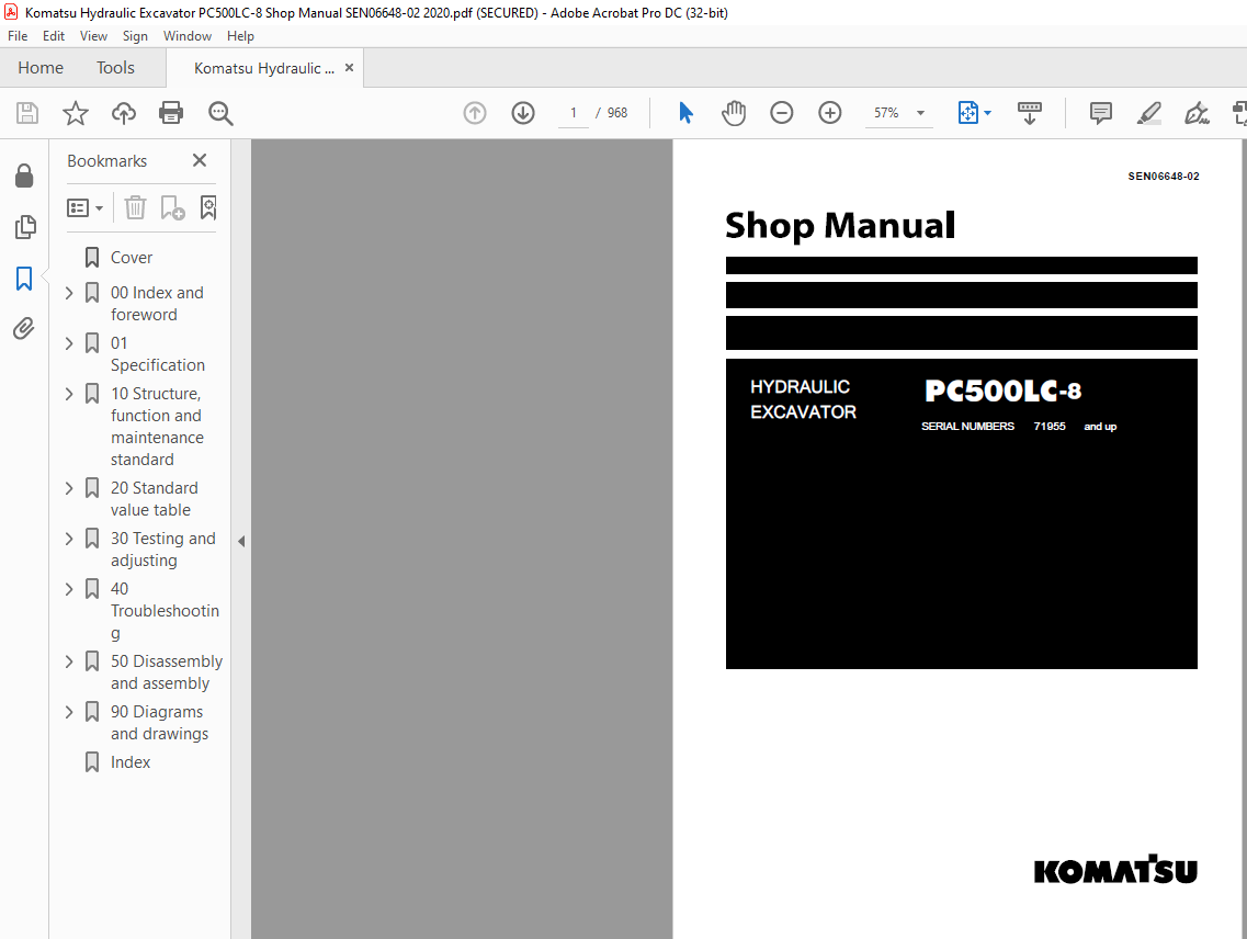
Komatsu PC500LC-8 Hydraulic Excavator Shop Manual SEN06648-02 – PDF DOWNLOAD
SERIAL NUMBERS 71955 and up
How to read the shop manual
1. Composition of shop manual
This shop manual contains the necessary technical information for services performed in a workshop.
For ease of understanding, the manual is divided into the following sections.
00. Index and foreword
This section explains the shop manuals list, table of contents, safety, and basic information.
01. Specification
This section explains the specifications of the machine.
10. Structure, function and maintenance standard
This section explains the structure, function, and maintenance standard values of each component.
The structure and function sub-section explains the structure and function of each component. It
serves not only to give an understanding of the structure, but also serves as reference material for
troubleshooting. The maintenance standard sub-section explains the criteria and remedies for disassembly
and service.
20. Standard value table
This section explains the standard values for new machine and judgement criteria for testing,
adjusting, and troubleshooting. This standard value table is used to check the standard values in
testing and adjusting and to judge parts in troubleshooting.
30. Testing and adjusting
This section explains measuring instruments and measuring methods for testing and adjusting, and
method of adjusting each part. The standard values and judgement criteria for testing and adjusting
are explained in Testing and adjusting.
40. Troubleshooting
This section explains how to find out failed parts and how to repair them. The troubleshooting is
divided by failure modes. The “S mode” of the troubleshooting related to the engine may be also
explained in the Chassis volume and Engine volume. In this case, see the Chassis volume.
50. Disassembly and assembly
This section explains the special tools and procedures for removing, installing, disassembling, and
assembling each component, as well as precautions for them. In addition, tightening torque and
quantity and weight of coating material, oil, grease, and coolant necessary for the work are also
explained.
90. Diagrams and drawings (chassis volume)/Repair and replacement of parts (engine volume)
q Chassis volume
This section gives hydraulic circuit diagrams and electrical circuit diagrams.
q Engine volume
This section explains the method of reproducing, repairing, and replacing parts.
TABLE OF CONTENTS:
Komatsu PC500LC-8 Hydraulic Excavator Shop Manual SEN06648-02 – PDF DOWNLOAD
Cover 1
00 Index and foreword 3
Table of contents 4
Foreword and general information 11
Safety notice 11
How to read the shop manual 16
Explanation of terms for maintenance standard 18
Handling of electric equipment and hydraulic component 20
Handling of connectors newly used for engines 29
How to read electric wire code 32
Precautions when carrying out operation 35
Method of disassembling and connecting push-pull type coupler 38
Standard tightening torque table 41
Conversion table 45
01 Specification 51
Specification and technical data 53
Specification dimension drawings 53
Specifications 55
Weight table 58
Table of fuel, coolant and lubricants 60
10 Structure, function and maintenance standard 63
Engine and cooling system 65
Engine related parts 65
Radiator, oil cooler and aftercooler 66
Power train 67
Power train 67
Swing circle 68
Swing machinery 70
Final drive 72
Sprocket 76
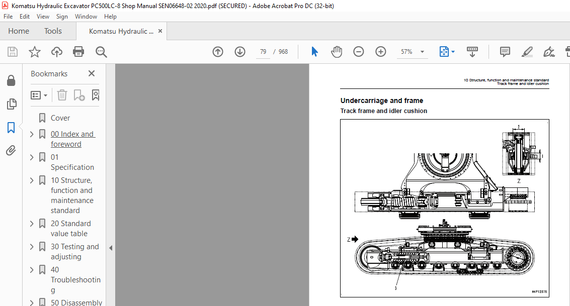
Undercarriage and frame 79
Track frame and idler cushion 79
Track shoe 80
Triple-grouser shoe 82
Idler 84
Carrier roller 86
Track roller 87
Hydraulic system 88
Hydraulic equipment layout drawing 88
Hydraulic tank and filter 90
Hydraulic pump 92
Control valve 116
CLSS 128
Functions and operation by valve 132
Merge-divider valve 147
Attachment circuit selector valve 172
Holding valve 174
Valve control 179
PPC valve 180
Solenoid valve 196
PPC accumulator 198
Return oil filter 199
Center swivel joint 200
Travel motor 201
Swing motor 217
Hydraulic cylinder 226
Work equipment 228
Work equipment 228
Dimensions of components 230
Cab and its attachments 234
Air conditioner piping 234
Electrical system 235
Engine control 235
Electronic control system 245
Monitor system 270
Sensors 297
KOMTRAX system 300
20 Standard value table 303
Standard service value table 305
Standard value table for engine 305
Standard value table for chassis related parts 306
30 Testing and adjusting 317
Related information on testing and adjusting 319
Tools for testing, adjusting and troubleshooting 319
Sketches of special tools 323
Engine and cooling system 324
Measuring engine speed 324
Measuring air boost pressure 325
Measuring exhaust gas temperature 326
Measuring exhaust gas color 327
Adjusting valve clearance 328
Measuring compression pressure 330
Measuring blow-by pressure 332
Testing engine oil pressure 333
Testing EGR valve drive pressure 334
Handling fuel system parts 335
Releasing residual pressure from fuel system 335
Measuring fuel pressure 336
Handling during cylinder cut-out operation 337
Handling during no injection cranking operation 337
Measuring fuel return rate and leakage 338
Bleeding air from fuel circuit 340
Checking fuel circuit for leakage 342
Checking and adjusting fan belt and alternator belt 343
Checking and adjusting air conditioner compressor belt tension 344
Power train 345
Testing swing circle bearing clearance 345
Undercarriage and frame 346
Testing and adjusting track shoe tension 346
Hydraulic system 347
Measuring and adjusting oil pressure in work equipment, swing, and travel circuits 347
Measuring control circuit basic pressure 351
Checking and adjusting pump PC control circuit oil pressure 352
Checking and adjusting pump LS control circuit oil pressure 355
Measuring solenoid valve output pressure 360
Measuring PPC valve output pressure 363
Adjusting play of work equipment and swing PPC valves 364
Inspecting locations of hydraulic drift of work equipment 365
Releasing residual pressure from hydraulic circuit 367
Measuring oil leakage amount 368
Bleeding air from various parts 371
Electrical system 374
Special functions of machine monitor 374
Handling voltage circuit of engine controller 427
Preparation work for troubleshooting of electrical system 428
Procedure for testing diodes 433
Pm Clinic 434
Pm Clinic service 434
Undercarriage troubleshooting report 440
40 Troubleshooting 441
Failure code table and fuse locations 446
Failure code table 446
Fuse locations 449
General Information on troubleshooting 454
Points to remember when troubleshooting 454
Sequence of events in troubleshooting 455
Check before troubleshooting 456
Classification and troubleshooting steps 457
Information in troubleshooting table 458
Possible problems and troubleshooting No 460
Connection table for connector pin numbers 462
T- branch box and T- branch adapter table 498
Troubleshooting by failure code 501
Failure code [989L00] Engine Controller Lock Caution 1 501
Failure code [989M00] Engine Controller Lock Caution 2 502
Failure code [989N00] Engine Controller Lock Caution 3 503
Failure code [AA10NX] Air cleaner Clogging 504
Failure code [AB00KE] Charge Voltage Low 506
Failure code [B@BAZG] Eng Oil Press Low 508
Failure code [B@BAZK] Eng Oil Level Low 510
Failure code [B@BCNS] Eng Water Overheat 512
Failure code [B@BCZK] Eng Water Level Low 514
Failure code [B@HANS] Hydr Oil Overheat 516
Failure code [CA111] EMC Critical Internal Failure 517
Failure code [CA115] Eng Ne and Bkup Speed Sens Error 519
Failure code [CA122] Chg Air Press Sensor High Error 520
Failure code [CA123] Chg Air Press Sensor Low Error 522
Failure code [CA131] Throttle Sensor High Error 524
Failure code [CA132] Throttle Sensor Low Error 526
Failure code [CA135] Eng Oil Press Sensor High Error 528
Failure code [CA141] Eng Oil Press Sensor Low Error 530
Failure code [CA144] Coolant Temp Sensor High Error 531
Failure code [CA145] Coolant Temp Sensor Low Error 533
Failure code [CA153] Chg Air Temp Sensor High Error 535
Failure code [CA154] Chg Air Temp Sensor Low Error 537
Failure code [CA187] Sens Supply 2 Volt Low Error 539
Failure code [CA221] Ambient Press Sens High Error 541
Failure code [CA222] Ambient Press Sens Low Error 543
Failure code [CA227] Sens Supply 2 Volt High Error 545
Failure code [CA234] Eng Overspeed 546
Failure code [CA238] Ne Speed Sens Supply Volt Error 547
Failure code [CA263] Fuel Temp Sensor High Error 548
Failure code [CA265] Fuel Temp Sensor Low Error 550
Failure code [CA271] IMV/PCV1 Short Error 551
Failure code [CA272] IMV/PCV1 Open Error 553
Failure code [CA273] PCV2 Short Error 555
Failure code [CA274] PCV2 Open Error 557
Failure code [CA322] Inj #1 Open/Short Error 559
Failure code [CA323] Inj #5 (L/B#5) Open/Short Error 561
Failure code [CA324] Inj #3 (L/B#3) Open/Short Error 563
Failure code [CA325] Inj #6 Open/Short Error 565
Failure code [CA331] Inj #2 Open/Short Error 567
Failure code [CA332] Inj #4 Open/Short Error 569
Failure code [CA342] Calibration Code Incompatibility 571
Failure code [CA351] Injectors Drive Circuit Error 572
Failure code [CA352] Sens Supply 1 Volt Low Error 574
Failure code [CA386] Sens Supply 1 Volt High Error 576
Failure code [CA441] Battery Voltage Low Error 578
Failure code [CA442] Battery Voltage High Error 580
Failure code [CA449] Rail Press Very High Error 582
Failure code [CA451] Rail Press Sensor High Error 585
Failure code [CA452] Rail Press Sensor Low Error 587
Failure code [CA553] Rail Press High Error 589
Failure code [CA554] Rail Press Sensor In Range Error 590
Failure code [CA559] Rail Press Low Error 591
Failure code [CA689] Eng Ne Speed Sensor Error 595
Failure code [CA731] Eng Bkup Speed Sens Phase Error 597
Failure code [CA757] All Continuous Data Lost Error 598
Failure code [CA778] Eng Bkup Speed Sensor Error 600
Failure code [CA1228] EGR valve servo error 1 602
Failure code [CA1625] EGR valve servo error 2 603
Failure code [CA1633] KOMNET Datalink Timeout Error 604
Failure code [CA2185] Throt Sens Sup Volt High Error 606
Failure code [CA2186] Throt Sens Sup Volt Low Error 608
Failure code [CA2249] Rail Press Very Low Error 609
Failure code [CA2271] EGR valve lift sensor high error 610
Failure code [CA2272] EGR valve lift sensor low error 612
Failure code [CA2351] EGR valve solenoid operation short circuit 613
Failure code [CA2352] EGR valve solenoid operation disconnect 615
Failure code [CA2555] Grid Htr Relay Volt Low Error 616
Failure code [CA2556] Grid Htr Relay Volt High Error 618
Failure code [D110KB] Battery Relay Drive S/C 620
Failure code [D19JKZ] Personal Code Relay Abnormality 622
Failure code [D862KA] GPS Antenna Discon 624
Failure code [DA22KK] Pump Solenoid Power Low Error 625
Failure code [DA25KP] 5V sensor power supply output 1 abnormality 627
Failure code [DA29KQ] Model Selection Abnormality 630
Failure code [DA2RMC] CAN Discon (Pump con detected) 632
Failure code [DAF8KB] Short circuit in camera power supply 634
Failure code [DAFGMC] GPS Module Error 636
Failure code [DAFRMC] CAN discon (Monitor detected) 637
Failure code [DGH2KB] Hyd Oil Sensor Short 639
Failure code [DHPAMA] F Pump Press Sensor Abnormality 640
Failure code [DHPBMA] R Pump Press Sensor Abnormality 642
Failure code [DHS3MA] Arm Curl PPC Press Sensor Abnormality 644
Failure code [DHS4MA] Bucket Curl PPC Press Sensor Abnormality 646
Failure code [DHX1MA] Overload Sensor Abnormality (Analog) 648
Failure code [DW43KA] Travel Speed Sol Open Circuit 649
Failure code [DW43KB] Travel Speed Sol Short Circuit 651
Failure code [DW45KA] Swing Brake Sol Open Circuit 653
Failure code [DW45KB] Swing Brake Sol Short Circuit 655
Failure code [DW91KA] Travel Junction Sol Open Circuit 657
Failure code [DW91KB] Travel Junction Sol Short Circuit 659
Failure code [DWA2KA] Attachment Sol Open Circuit 661
Failure code [DWA2KB] Attachment Sol Short Circuit 662
Failure code [DWJ0KA] Merge-divider Sol Open Circuit 663
Failure code [DWJ0KB] Merge-divider Sol Short Circuit 665
Failure code [DWK0KA] 2-stage Relief Sol Open Circuit 667
Failure code [DWK0KB] 2-stage Relief Sol Short Circuit 669
Failure code [DXA0KA] PC-EPC Sol Open Circuit 671
Failure code [DXA0KB] PC-EPC Sol Short Circuit 673
Failure code [DXE0KA] LS-EPC Sol Open Circuit 675
Failure code [DXE0KB] LS-EPC Sol Short Circuit 677
Failure code [DXE4KA] Service Current EPC Open Circuit 679
Failure code [DXE4KB] Service Current EPC Short Circuit 680
Failure code [DY20KA] Wiper Working Abnormality 681
Failure code [DY20MA] Wiper Parking Abnormality 683
Failure code [DY2CKA] Washer Drive Open Discon 685
Failure code [DY2CKB] Washer Drive Short Circuit 687
Failure code [DY2DKB] Wiper Drive (Fwd) Short Circuit 689
Failure code [DY2EKB] Wiper Drive (Rev) Short Circuit 691
Troubleshooting of electrical system (E-mode) 693
Before carrying out troubleshooting of electrical system 693
Information contained in troubleshooting table 695
E-1 Engine does not start 696
E-2 Auto-decelerator does not operate 699
E-3 Automatic warming-up system does not operate 701
E-4 Preheater does not operate 702
E-5 All work equipment, swing, and travel mechanism do not move 704
E-6 Power maximizing function does not operate 706
E-7 Machine monitor does not display at all 707
E-8 Machine monitor does not display some items 709
E-9 Contents of display by machine monitor are different from applicable machine 709
E-10 Fuel level monitor was lighted in red while engine running 710
E-11 Engine coolant temperature gauge does not indicate normally 711
E-12 Hydraulic oil temperature gauge does not indicate normally 713
E-13 Fuel level gauge does not indicate normally 714
E-14 Swing lock monitor does not indicate normally 715
E-15 When monitor switch is operated, monitor displays nothing 717
E-16 Windshield wiper and window washer do not operate 718
E-17 Machine push-up function does not operate normally 722
E-18 Monitoring function fails to display “boom raise” normally 724
E-19 Monitoring function fails to display “boom lower” normally 726
E-20 Monitoring function fails to display “arm IN” normally 728
E-21 Monitoring function fails to display “arm OUT” normally 729
E-22 Monitoring function fails to display “bucket CURL” normally 731
E-23 Monitoring function fails to display “bucket DUMP” normally 732
E-24 Monitoring function fails to display “swing” normally 734
E-25 Monitoring function fails to display “travel” normally 736
E-26 Monitoring function fails to display “travel differential pressure” normally 738
E-27 Monitoring function fails to display “service” normally 740
E-28 KOMTRAX system does not operate normally 742
E-29 Air conditioner does not operate 743
E-30 Travel alarm does not sound or does not stop sounding 745
E-31 Horn does not sound 747
Troubleshooting of hydraulic and mechanical system (H-mode) 750
System chart for hydraulic and mechanical system 750
Information contained in troubleshooting table 752
H-1 All work equipment lack power, or travel and swing speeds are slow 753
H-2 Engine speed sharply drops or engine stalls 755
H-3 No work equipment, swing or travel move 756
H-4 Abnormal noise is heard from around hydraulic pump 756
H-5 Auto-decelerator does not work 757
H-6 Fine control mode does not function or responds slow 757
H-7 Boom moves slowly or lacks power 758
H-8 Arm moves slowly or lacks power 759
H-9 Bucket moves slowly or lacks power 760
H-10 Work equipment does not move in its single operation 760
H-11 Work equipment has a bit too fast hydraulic drift 761
H-12 Work equipment has big time lag 763
H-13 Other work equipment moves when relieving single circuit 763
H-14 Power max switch does not operate 763
H-15 Machine push-up function does not operate 764
H-16 In compound operation of work equipment, speed of part loaded more is low 765
H-17 When machine swings and raises boom simultaneously, boom rising speed is low 765
H-18 When machine swings and travels simultaneously, travel speed lowers largely 765
H-19 Machine deviates during travel 766
H-20 Travel speed is low 767
H-21 Machine is not steered well or steering power is low 768
H-22 Travel speed does not change or travel speed is low or high 769
H-23 Travel system does not move (only one side) 770
H-24 Upper structure does not swing 771
H-25 Swing acceleration or swing speed is low 773
H-26 Upper structure overruns remarkably when it stops swinging 775
H-27 Large shock is made when upper structure stops swinging 776
H-28 Large sound is made when upper structure stops swinging 776
H-29 Hydraulic drift of swing is large 777
H-30 Attachment circuit is not changed 778
H-31 Oil flow in attachment circuit cannot be controlled 778
Troubleshooting of engine (S-mode) 779
Method of using troubleshooting chart 779
S-1 Starting performance is poor 782
S-2 Engine does not start 784
S-3 Engine does not pick up smoothly 788
S-4 Engine stops during operations 789
S-5 Engine does not rotate smoothly 790
S-6 Engine lacks output (or lacks power) 791
S-7 Exhaust smoke is black (incomplete combustion) 792
S-8 Oil consumption is excessive (or exhaust smoke is blue) 793
S-9 Oil becomes contaminated quickly 794
S-10 Fuel consumption is excessive 795
S-11 Oil is in coolant (or coolant spurts back or coolant level goes down) 796
S-12 Oil pressure drops 797
S-13 Oil level rises (Entry of coolant or fuel) 798
S-14 Coolant temperature becomes too high (overheating) 800
S-15 Abnormal noise is made 801
S-16 Vibration is excessive 802
50 Disassembly and assembly 803
Related information on disassembly and assembly 806
How to read this manual 806
Coating materials list 808
Special tools list 811
Sketches of special tools 814
Engine and cooling system 818
Removal and installation of fuel supply pump assembly 818
Removal and installation of fuel injector assembly 822
Removal and installation of engine front seal 828
Removal and installation of engine rear seal 829
Removal and installation of cylinder head assembly 832
Removal and installation of radiator assembly 841
Removal and installation of hydraulic oil cooler assembly 843
Removal and installation of aftercooler assembly 845
Removal and installation of engine and hydraulic oil pump assembly 846
Power train 853
Removal and installation of travel motor and final drive assembly 853
Disassembly and assembly of final drive 854
Removal and installation of swing motor and swing machinery assembly 862
Disassembly and assembly of swing motor and swing machinery assembly 863
Removal and installation of swing circle assembly 870
Undercarriage and frame 871
Separation and connection of track shoe assembly 871
Removal and installation of sprocket 873
Removal and installation of idler and idler cushion assembly 874
Disassembly and assembly of idler 875
Disassembly and assembly of idler cushion 878
Disassembly and assembly of track roller 880
Disassembly and assembly of carrier roller 881
Removal and installation of revolving frame assembly 883
Removal and installation of counterweight assembly 886
Hydraulic system 889
Removal and installation of center swivel joint assembly 889
Disassembly and assembly of center swivel joint assembly 891
Removal and installation of hydraulic tank assembly 892
Removal and installation of control valve assembly 894
Disassembly and assembly of control valve assembly 897
Removal and installation of hydraulic pump assembly 899
Removal and installation of oil seal in hydraulic pump input shaft 902
Disassembly and assembly of work equipment PPC valve assembly 903
Disassembly and assembly of travel PPC valve assembly 904
Disassembly and assembly of hydraulic cylinder assembly 905
Work equipment 911
Removal and installation of work equipment assembly 911
Cab and its attachments 914
Removal and installation of operator cab assembly 914
Removal and installation of operator cab glass (stuck glass) 917
Removal and installation of front window assembly 927
Removal and installation of floor frame assembly 934
Electrical system 938
Removal and installation of air conditioner unit assembly 938
Removal and installation of KOMTRAX communication modem assembly 941
Removal and installation of monitor assembly 942
Removal and installation of pump controller assembly 944
Removal and installation of engine controller 946
90 Diagrams and drawings 947
Hydraulic diagrams and drawings 949
Hydraulic circuit diagram 949
Electrical diagrams and drawings 951
Electrical circuit diagram 951
Connector arrangement diagram 961
Index 963
VIDEO PREVIEW OF THE MANUAL:
IMAGES PREVIEW OF THE MANUAL:
More products