$43
Komatsu PC500LC-8R Hydraulic Excavator Shop Manual SEN06614-01 – PDF DOWNLOAD
Komatsu PC500LC-8R Hydraulic Excavator Shop Manual SEN06614-01 – PDF DOWNLOAD
FILE DETAILS:
Komatsu PC500LC-8R Hydraulic Excavator Shop Manual SEN06614-01 – PDF DOWNLOAD
Language : English
Pages : 960
Downloadable : Yes
File Type : PDF
Size: 75 MB
DESCRIPTION:
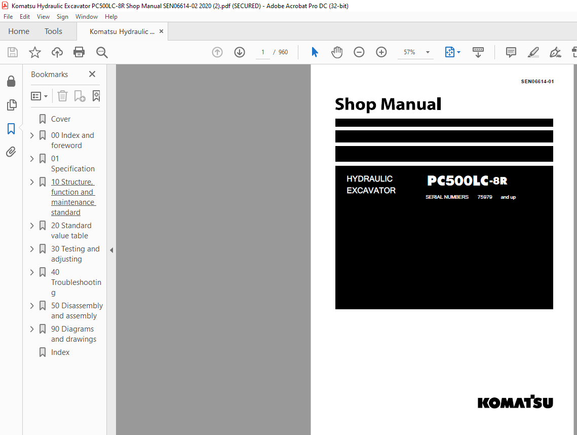
Komatsu PC500LC-8R Hydraulic Excavator Shop Manual SEN06614-01 – PDF DOWNLOAD
SERIAL NUMBERS 75979 and up
General precautions:
• Before performing any greasing or repairs, read all the safety labels stuck to the machine. For the locations of the safety labels and detailed explanation of precautions, see the operation and maintenance manual.• Locate a place in the repair workshop to keep the tools and removed parts. Always keep the tools and parts in their correct places. Always keep the work area clean and make sure that there is no dirt, water or oil on the floor. Smoke only in the areas provided for smoking. Never smoke while working.• When performing any work, always wear the safety shoes and helmet. Do not wear loose work cloths, or clothes with buttons missing. 1. Always wear the protective eyeglasses when hitting parts with a hammer.Always wear the protective eyeglasses when grinding parts with a grinder, etc.• When performing any work with 2 or more workers, always agree on the working procedure before starting. While working, always keep conversations of the work between your fellow workers and your self on any step of the work. During the work, hang the warning tag of “UNDER WORKING” in the operator’s compartment.• Only qualified workers must perform the work and operation which require license or qualification.• Keep the tools in good condition. And learn the correct way to use the tools, and use the proper ones among them. Before starting the work, thoroughly check the tools, lift truck, service vehicle, etc.• If welding repairs is required, always have a trained and experienced welder with good knowledge of welding perform the work. When performing welding work, always wear welding gloves, apron, shielding goggles, cap, etc.• Before starting work, warm up your body thoroughly to start work under good condition.• Avoid continuing work for long hours and take rests with proper intervals to keep your body in good condition. Take a rest in a specified safe place.
How to read the shop manual :
• Some attachments and optional parts described in this shop manual may not be arranged for certain
areas. Contact your Komatsu distributor if one or some of them are required.
• Materials and specifications are subject to change without notice.
• The shop manuals are available for “Machine part” and “Engine part”. For the engine, see the shop
manual for the same model of the engine as the one which is mounted on the machine.
Composition of shop manual
• This shop manual describes the technical information required for the services performed in a workshop.
The shop manual is divided into the following chapters for the convenience of use.
00. Index and foreword
• This section includes the index, foreword, safety and basic information.
01. Specification
• This section explains the specifications of the machine.
10. Structure and function
• This section explains the structure and function of the machine. The section of “Structure and function”
serves not only to give an understanding for the structure of each component, but also serves as
reference material for troubleshooting.
20. Standard value table
• The standard values for a new machine and trouble shooting are indicated. This standard value table is
used for testing and adjusting, and determining a failure at troubleshooting.
30. Testing and adjusting
• This section describes the measuring tools and how to measure, and how to adjust various parts. As for
the standard value and failure criterion, see the standard value table.
40. Troubleshooting
• This section describes the troubleshooting in a suspected area when a failure occurs and the remedy for
the failure. Troubleshooting is described by each failure mode.
50. Disassembly and assembly
• This section explains the procedures for removing, installing, disassembling, and assembling each part or
component and the special tools for the works as well as precautions for doing them safely. In addition,
tightening torque, and quantity and weight of coating material, oil, grease, and coolant required for the
works are also explained.
60. Maintenance standard
• This section describes the maintenance standard values for each component. This section gives the
criterion values for each component and required remedy at disassembly or maintenance.
80. Appendix
• The structure and function, testing and adjusting, and troubleshooting for all of the other components or
equipment which can not be separately classified are explained together in the appendix.
90. Diagrams and drawings
• This section gives hydraulic circuit diagrams and electrical circuit diagrams.
TABLE OF CONTENTS:
Komatsu PC500LC-8R Hydraulic Excavator Shop Manual SEN06614-01 – PDF DOWNLOAD
Cover 1
00 Index and foreword 3
Table of contents 4
Foreword and general information 11
Safety notice 11
How to read the shop manual 16
Explanation of terms for maintenance standard 18
Handling of electric equipment and hydraulic component 20
Handling of connectors newly used for engines 29
How to read electric wire code 32
Precautions when carrying out operation 35
Method of disassembling and connecting push-pull type coupler 38
Standard tightening torque table 41
Conversion table 45
01 Specification 51
Specification and technical data 53
Specification dimension drawings 53
Specifications 55
Weight table 58
Table of fuel, coolant and lubricants 60
10 Structure, function and maintenance standard 63
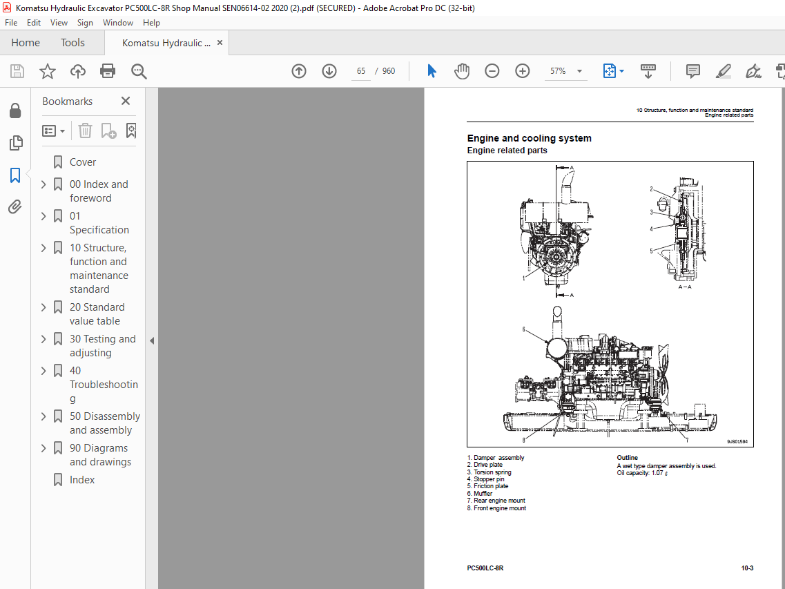
Engine and cooling system 65
Engine related parts 65
Radiator, oil cooler and aftercooler 66
Power train 67
Power train 67
Swing circle 68
Swing machinery 70
Final drive 72
Sprocket 76
Undercarriage and frame 79
Track frame and idler cushion 79
Track shoe 80
Triple-grouser shoe 82
Idler 84
Carrier roller 86
Track roller 87
Hydraulic system 88
Hydraulic equipment layout drawing 88
Hydraulic tank and filter 90
Hydraulic pump 92
Control valve 116
CLSS 128
Functions and operation by valve 132
Merge-divider valve 147
Attachment circuit selector valve 172
Holding valve 174
Valve control 179
PPC valve 180
Solenoid valve 196
PPC accumulator 198
Return oil filter 199
Center swivel joint 200
Travel motor 201
Swing motor 217
Hydraulic cylinder 226
Work equipment 228
Work equipment 228
Dimensions of components 230
Cab and its attachments 234
Air conditioner piping 234
Electrical system 235
Engine control 235
Electronic control system 245
Monitor system 270
Sensors 297
KOMTRAX system 300
20 Standard value table 303
Standard service value table 305
Standard value table for engine related parts 305
Standard value table for chassis related parts 306
30 Testing and adjusting 317
Related information on testing and adjusting 319
Tools for testing, adjusting and troubleshooting 319
Sketches of special tools 323
Engine and cooling system 324
Measuring engine speed 324
Measuring air boost pressure 325
Measuring exhaust gas temperature 326
Measuring exhaust gas color 327
Adjusting valve clearance 328
Measuring compression pressure 330
Measuring blow-by pressure 332
Testing engine oil pressure 333
Handling fuel system parts 334
Releasing residual pressure from fuel system 334
Measuring fuel pressure 335
Handling during cylinder cut-out operation 336
Handling during no injection cranking operation 336
Measuring fuel return rate and leakage 337
Bleeding air from fuel circuit 339
Checking fuel circuit for leakage 343
Checking and adjusting fan belt and alternator belt 344
Checking and adjusting air conditioner compressor belt tension 345
Power train 346
Testing swing circle bearing clearance 346
Undercarriage and frame 347
Testing and adjusting track shoe tension 347
Hydraulic system 348
Measuring and adjusting oil pressure in work equipment, swing, and travel circuits 348
Measuring control circuit basic pressure 352
Checking and adjusting pump PC control circuit oil pressure 353
Checking and adjusting pump LS control circuit oil pressure 356
Measuring solenoid valve output pressure 361
Measuring PPC valve output pressure 364
Adjusting play of work equipment and swing PPC valves 365
Inspecting locations of hydraulic drift of work equipment 366
Releasing residual pressure from hydraulic circuit 368
Measuring oil leakage amount 369
Bleeding air from various parts 372
Electrical system 376
Special functions of machine monitor 376
Handling voltage circuit of engine controller 429
Preparation work for troubleshooting of electrical system 430
Procedure for testing diodes 435
Pm Clinic 436
Pm Clinic service 436
Undercarriage troubleshooting report 442
40 Troubleshooting 443
General Information on troubleshooting 448
Points to remember when troubleshooting 448
Sequence of events in troubleshooting 449
Check before troubleshooting 450
Classification and troubleshooting steps 451
Information in troubleshooting table 452
Connection table for connector pin numbers 457
T- branch box and T- branch adapter table 493
Failure code table and fuse locations 496
Failure codes table 496
Fuse locations 498
Troubleshooting by failure code (Display of code) 500
Failure code [AA10NX] Air cleaner Clogging 500
Failure code [AB00KE] Charge Voltage Low 502
Failure code [B@BAZG] Eng Oil Press Low 504
Failure code [B@BAZK] Eng Oil Level Low 507
Failure code [B@BCNS] Eng Water Overheat 508
Failure code [B@BCZK] Eng Water Level Low 510
Failure code [B@HANS] Hydr Oil Overheat 512
Failure code [CA111] EMC Critical Internal Failure 513
Failure code [CA115] Eng Ne and Bkup Speed Sens Error 513
Failure code [CA122] Chg Air Press Sensor High Error 514
Failure code [CA123] Chg Air Press Sensor Low Error 516
Failure code [CA131] Throttle Sensor High Error 518
Failure code [CA132] Throttle Sensor Low Error 520
Failure code [CA135] Eng Oil Press Sensor High Error 522
Failure code [CA141] Eng Oil Press Sensor Low Error 525
Failure code [CA144] Coolant Temp Sens High Error 526
Failure code [CA145] Coolant Temp Sens Low Error 528
Failure code [CA153] Chg Air Temp Sensor High Error 530
Failure code [CA154] Chg Air Temp Sensor Low Error 532
Failure code [CA187] Sens Supply 2 Volt Low Error 534
Failure code [CA221] Ambient Press Sens High Error 536
Failure code [CA222] Ambient Press Sens Low Error 538
Failure code [CA227] Sens Supply 2 Volt High Error 540
Failure code [CA234] Eng Overspeed 541
Failure code [CA238] Ne Speed Sens Supply Volt Error 543
Failure code [CA263] Fuel Temp Sensor High Error 544
Failure code [CA265] Fuel Temp Sensor Low Error 546
Failure code [CA271] IMV/PCV1 Short Error 547
Failure code [CA272] IMV/PCV1 Open Error 548
Failure code [CA273] PCV2 Short Error 550
Failure code [CA274] PCV2 Open Error 552
Failure code [CA322] Inj #1 Open/Short Error 554
Failure code [CA323] Inj #5 Open/Short Error 556
Failure code [CA324] Inj #3 Open/Short Error 558
Failure code [CA325] Inj #6 Open/Short Error 560
Failure code [CA331] Inj #2 Open/Short Error 562
Failure code [CA332] Inj #4 Open/Short Error 564
Failure code [CA342] Calibration Code Incompatibility 566
Failure code [CA351] Injectors Drive Circuit Error 568
Failure code [CA352] Sens Supply 1 Volt Low Error 570
Failure code [CA386] Sens Supply 1 Volt High Error 572
Failure code [CA441] Battery Voltage Low Error 574
Failure code [CA442] Battery Voltage High Error 576
Failure code [CA449] Rail Press Very High Error 578
Failure code [CA451] Rail Press Sensor High Error 582
Failure code [CA452] Rail Press Sensor Low Error 584
Failure code [CA553] Rail Press High Error 586
Failure code [CA554] Rail Press Sensor In Range Error 587
Failure code [CA559] Rail Press Low Error 588
Failure code [CA689] Eng Ne Speed Sensor Error 590
Failure code [CA731] Eng Bkup Speed Sens Phase Error 592
Failure code [CA757] All Persistent Data Lost Error 594
Failure code [CA778] Eng Bkup Speed Sensor Error 596
Failure code [CA1633] KOMNET Datalink Timeout Error 598
Failure code [CA2185] Throt Sens Sup Volt High Error 600
Failure code [CA2186] Throt Sens Sup Volt Low Error 601
Failure code [CA2249] Rail Press Very Low Error 602
Failure code [CA2555] Grid Htr Relay Volt High Error 604
Failure code [CA2556] Grid Htr Relay Volt Low Error 606
Failure code [D110KB] Battery Relay Drive S/C 608
Failure code [D196KA] Service Return Relay Disc 610
Failure code [D196KB] Service Return Relay S/C 612
Failure code [DA25KP] 5V sensor power supply output 1 abnormality 614
Failure code [DA2SKQ] Model Selection Abnormality 618
Failure code [DA2RMC] CAN discon (Pump con detected) 620
Failure code [DAFRMC] CAN discon (Monitor detected) 622
Failure code [DHPAMA] F Pump Press Sensor Abnormality 624
Failure code [DHPBMA] R Pump Press Sensor Abnormality 626
Failure code [DHS3MA] Arm Curl PPC Sen Abnormality 628
Failure code [DHS4MA] Bucket Curl PPC Press Sensor Abnormality 630
Failure code [DW43KA] Travel Speed Sol Disc 632
Failure code [DW43KB] Travel Speed Sol S/C 634
Failure code [DW45KA] Swing Brake Sol Disc 636
Failure code [DW45KB] Swing Brake Sol S/C 640
Failure code [DW91KA] Travel Junction Sol Disc 642
Failure code [DW91KB] Travel Junction Sol S/C 644
Failure code [DWA2KA] Attachment Sol Open Circuit 646
Failure code [DWJ0KA] Merge-divider Sol Disc 648
Failure code [DWJ0KB] Merge-divider Sol S/C 650
Failure code [DWK0KA] 2-stage Relief Sol Disc 652
Failure code [DWK0KB] 2-stage Relief Sol S/C 654
Failure code [DXA0KA] PC-EPC Sol Disc 656
Failure code [DXA0KB] PC-EPC Sol S/C 658
Failure code [DXE0KA] LS-EPC Sol Disc 660
Failure code [DXE0KB] LS-EPC Sol S/C 662
Failure code [DXE4KA] Service Current EPC Disc 664
Failure code [DXE4KB] Service Current EPC S/C 665
Failure code [DY20KA] Wiper Working Abnormality 666
Failure code [DY20MA] Wiper Parking Abnormality 668
Failure code [DY2CKB] Washer Drive Short 670
Failure code [DY2DKB] Wiper Drive (For) Short 672
Failure code [DY2EKB] Wiper Drive (Rev) Short 674
Troubleshooting of electrical system (E-mode) 676
Before carrying out troubleshooting of electrical system 676
Information contained in troubleshooting table 678
E-1 Engine does not start 679
E-2 Auto-decelerator does not operate 682
E-3 Automatic warming-up system does not operate 684
E-4 Preheater does not operate 686
E-5 All work equipment, swing, and travel mechanism do not move 688
E-6 Power maximizing function does not operate 690
E-7 Machine monitor does not display at all 692
E-8 Machine monitor does not display some items 694
E-9 Contents of display by machine monitor are different from applicable machine 694
E-10 Fuel level monitor was lighted in red while engine running 695
E-11 Engine coolant temperature gauge does not indicate normally 696
E-12 Hydraulic oil temperature gauge does not indicate normally 698
E-13 Fuel level gauge does not indicate normally 699
E-14 Swing lock monitor does not indicate normally 700
E-15 When monitor switch is operated, monitor displays nothing 702
E-16 Windshield wiper and window washer do not operate 704
E-17 Machine push-up function does not operate normally 708
E-18 Monitoring function fails to display “boom raise” normally 710
E-19 Monitoring function fails to display “boom lower” normally 712
E-20 Monitoring function fails to display “arm IN” normally 714
E-21 Monitoring function fails to display “arm OUT” normally 716
E-22 Monitoring function fails to display “bucket CURL” normally 718
E-23 Monitoring function fails to display “bucket DUMP” normally 720
E-24 Monitoring function fails to display “swing” normally 722
E-25 Monitoring function fails to display “travel” normally 724
E-26 Monitoring function fails to display “travel differential pressure” normally 726
E-27 Monitoring function fails to display “service” normally 728
E-28 KOMTRAX system does not operate normally 730
E-29 Air conditioner does not operate 732
E-30 Travel alarm does not sound or does not stop sounding 734
E-31 Horn does not sound 736
E-32 Electric priming pump does not operate or does not stop automatically 738
Troubleshooting of hydraulic and mechanical system (H-mode) 740
System chart for hydraulic and mechanical system 740
Information contained in troubleshooting table 742
H-1 All work equipment lack power, or travel and swing speeds are slow 744
H-2 Engine speed sharply drops or engine stalls 746
H-3 No work equipment, swing or travel move 747
H-4 Abnormal noise is heard from around hydraulic pump 747
H-5 Auto-decelerator does not work 748
H-6 Fine control mode does not function or responds slow 748
H-7 Boom moves slowly or lacks power 749
H-8 Arm moves slowly or lacks power 750
H-9 Bucket moves slowly or lacks power 751
H-10 Work equipment does not move in its single operation 751
H-11 Work equipment has a bit too fast hydraulic drift 752
H-12 Work equipment has big time lag 754
H-13 Other work equipment moves when relieving single circuit 754
H-14 Power max switch does not operate 754
H-15 Machine push-up function does not operate 755
H-16 In compound operation of work equipment, speed of part loaded more is low 756
H-17 When machine swings and raises boom simultaneously, boom rising speed is low 756
H-18 When machine swings and travels simultaneously, travel speed lowers largely 756
H-19 Machine deviates during travel 757
H-20 Travel speed is low 758
H-21 Machine is not steered well or steering power is low 759
H-22 Travel speed does not change or travel speed is low or high 760
H-23 Travel system does not move (only one side) 761
H-24 Upper structure does not swing 762
H-25 Swing acceleration or swing speed is low 764
H-26 Upper structure overruns remarkably when it stops swinging 766
H-27 Large shock is made when upper structure stops swinging 767
H-28 Large sound is made when upper structure stops swinging 767
H-29 Hydraulic drift of swing is large 768
H-30 Attachment circuit is not changed 769
H-31 Oil flow in attachment circuit cannot be controlled 769
Troubleshooting of engine (S-mode) 771
Method of using troubleshooting chart 771
S-1 Starting performance is poor 774
S-2 Engine does not start 775
S-3 Engine does not pick up smoothly 778
S-4 Engine stops during operations 779
S-5 Engine does not rotate smoothly 780
S-6 Engine lacks output (or lacks power) 781
S-7 Exhaust smoke is black (incomplete combustion) 782
S-8 Oil consumption is excessive (or exhaust smoke is blue) 783
S-9 Oil becomes contaminated quickly 784
S-10 Fuel consumption is excessive 785
S-11 Oil is in coolant (or coolant spurts back or coolant level goes down) 786
S-12 Oil pressure drops 787
S-13 Oil level rises (Entry of coolant or fuel) 788
S-14 Coolant temperature becomes too high (overheating) 789
S-15 Abnormal noise is made 790
S-16 Vibration is excessive 791
S-17 Air cannot be bled from fuel circuit 792
50 Disassembly and assembly 793
Related information on disassembly and assembly 796
How to read this manual 796
Coating materials list 798
Special tools list 801
Sketches of special tools 804
Engine and cooling system 808
Removal and installation of fuel supply pump assembly 808
Removal and installation of fuel injector assembly 812
Removal and installation of engine front seal 818
Removal and installation of engine rear seal 819
Removal and installation of cylinder head assembly 822
Removal and installation of radiator assembly 831
Removal and installation of hydraulic oil cooler assembly 833
Removal and installation of aftercooler assembly 835
Removal and installation of engine and hydraulic oil pump assembly 836
Power train 843
Removal and installation of travel motor and final drive assembly 843
Disassembly and assembly of final drive 844
Removal and installation of swing motor and swing machinery assembly 852
Disassembly and assembly of swing motor and swing machinery assembly 853
Removal and installation of swing circle assembly 860
Undercarriage and frame 861
Separation and connection of track shoe assembly 861
Removal and installation of sprocket 863
Removal and installation of idler and idler cushion assembly 864
Disassembly and assembly of idler 865
Disassembly and assembly of idler cushion 868
Disassembly and assembly of track roller 870
Disassembly and assembly of carrier roller 871
Removal and installation of revolving frame assembly 873
Removal and installation of counterweight assembly 876
Hydraulic system 879
Removal and installation of center swivel joint assembly 879
Disassembly and assembly of center swivel joint assembly 881
Removal and installation of hydraulic tank assembly 882
Removal and installation of control valve assembly 884
Disassembly and assembly of control valve assembly 887
Removal and installation of hydraulic pump assembly 889
Removal and installation of oil seal in hydraulic pump input shaft 892
Disassembly and assembly of work equipment PPC valve assembly 893
Disassembly and assembly of travel PPC valve assembly 894
Disassembly and assembly of hydraulic cylinder assembly 895
Work equipment 901
Removal and installation of work equipment assembly 901
Cab and its attachments 904
Removal and installation of operator cab assembly 904
Removal and installation of operator cab glass (stuck glass) 907
Removal and installation of front window assembly 917
Removal and installation of floor frame assembly 924
Electrical system 928
Removal and installation of air conditioner unit assembly 928
Removal and installation of KOMTRAX communication modem assembly 931
Removal and installation of monitor assembly 932
Removal and installation of pump controller assembly 934
Removal and installation of engine controller 936
90 Diagrams and drawings 937
Hydraulic diagrams and drawings 939
Hydraulic circuit diagram 939
Electrical diagrams and drawings 941
Electrical circuit diagram 941
Connector arrangement diagram 951
Index 953
IMAGES PREVIEW OF THE MANUAL:
More products