$33
Komatsu PC750-7 PC750LC-7 PC750SE-7 PC800-7 PC800SE-7 Excavator Field Assembly Manual PDF
Komatsu PC750-7 PC750LC-7 PC750SE-7 PC800-7 PC800SE-7 Hydraulic Excavator Field Assembly Instruction Manual GEN00014-04 – PDF DOWNLOAD
FILE DETAILS:
Komatsu PC750-7 PC750LC-7 PC750SE-7 PC800-7 PC800SE-7 Hydraulic Excavator Field Assembly Instruction Manual GEN00014-04 – PDF DOWNLOAD
Language : English
Pages : 160
Downloadable : Yes
File Type : PDF
Size: 11.6 MB
IMAGES PREVIEW OF THE MANUAL:
DESCRIPTION:
Komatsu PC750-7 PC750LC-7 PC750SE-7 PC800-7 PC800SE-7 Hydraulic Excavator Field Assembly Instruction Manual GEN00014-04 – PDF DOWNLOAD
SERIAL NUMBERS
PC750-20001 and up
PC800-40001 and up
- The Komatsu PC750-7 PC750LC-7 PC750SE-7 PC800-7 PC800SE-7 Hydraulic Excavator Field Assembly Instruction Manual (GEN00014-04) is a comprehensive guide for individuals who are involved in the assembly of Komatsu hydraulic excavators. The manual provides step-by-step instructions for the assembly of various components of the hydraulic excavator, including the engine, hydraulic system, electrical system, and more. The manual is designed to help users ensure that the hydraulic excavator is assembled correctly and efficiently, and provides information on the latest tools and technologies used in the assembly process.
- One of the key features of the Komatsu PC750-7 PC750LC-7 PC750SE-7 PC800-7 PC800SE-7 Hydraulic Excavator Field Assembly Instruction Manual is its clear and concise instructions. The manual provides step-by-step instructions for each assembly procedure, and includes detailed illustrations and schematics to help users understand the process. The instructions are easy to follow, and are designed to help users avoid common mistakes that can lead to incorrect assembly or damage to the hydraulic excavator.
- Another valuable aspect of the Komatsu PC750-7 PC750LC-7 PC750SE-7 PC800-7 PC800SE-7 Hydraulic Excavator Field Assembly Instruction Manual is its comprehensive coverage of the hydraulic excavator components. The manual includes information on the assembly of various components, including the engine, hydraulic system, electrical system, and more. The information is presented in an easy-to-understand format, and includes clear explanations of each step of the assembly process.
- The Komatsu PC750-7 PC750LC-7 PC750SE-7 PC800-7 PC800SE-7 Hydraulic Excavator Field Assembly Instruction Manual also includes information on the latest tools and technologies used in the assembly of hydraulic excavators. This information can help users take advantage of the latest advancements in the field to assemble their hydraulic excavator more efficiently and effectively.
- Overall, the Komatsu PC750-7 PC750LC-7 PC750SE-7 PC800-7 PC800SE-7 Hydraulic Excavator Field Assembly Instruction Manual is an essential resource for individuals involved in the assembly of Komatsu hydraulic excavators. It provides a wealth of information that can help users assemble their hydraulic excavator correctly and efficiently, and can save them time and money by enabling them to avoid common mistakes and avoid the need for costly repairs. The manual is a valuable resource for anyone who wants to ensure that their hydraulic excavator is assembled properly and is ready to perform at its best.
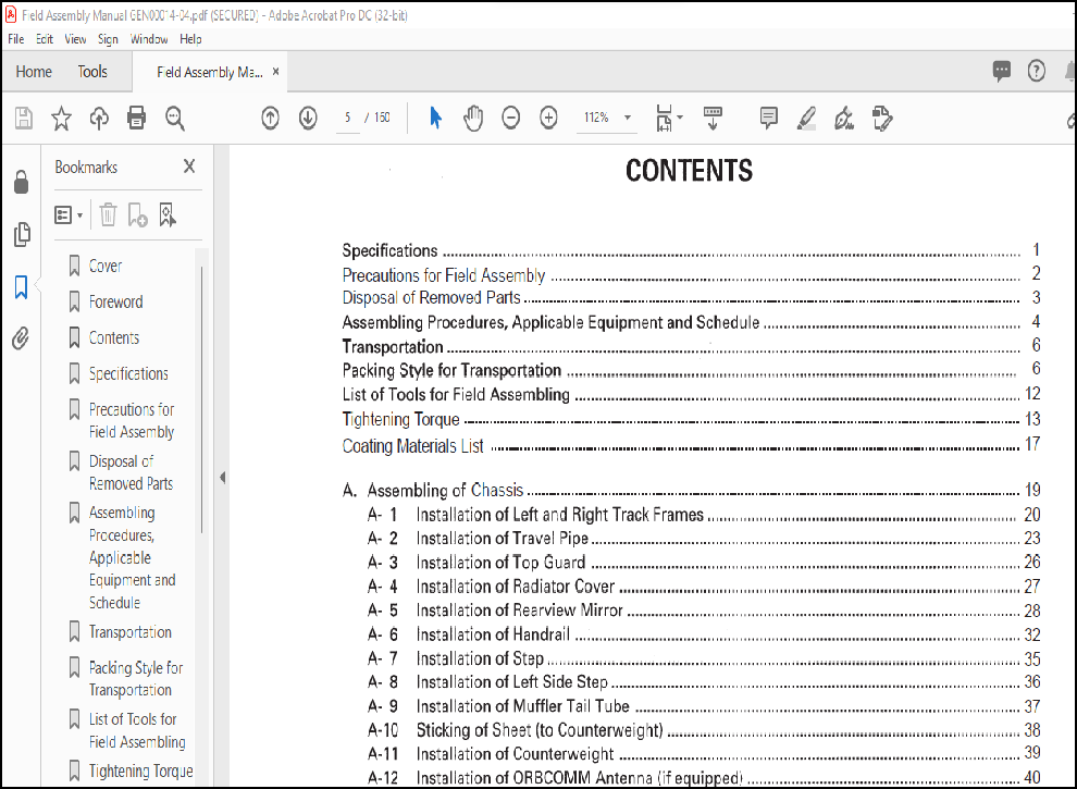
TABLE OF CONTENTS:
Komatsu PC750-7 PC750LC-7 PC750SE-7 PC800-7 PC800SE-7 Hydraulic Excavator Field Assembly Instruction Manual GEN00014-04 – PDF DOWNLOAD
Cover………………………………………………………………………. 1
Foreword……………………………………………………………………. 3
Contents……………………………………………………………………. 5
Specifications………………………………………………………………. 7
Precautions for Field Assembly………………………………………………… 8
Disposal of Removed Parts…………………………………………………….. 9
Assembling Procedures, Applicable Equipment and Schedule…………………………. 10
Transportation………………………………………………………………. 12
Packing Style for Transportation………………………………………………. 12
List of Tools for Field Assembling…………………………………………….. 18
Tightening Torque……………………………………………………………. 19
Coating Materials List……………………………………………………….. 23
A. Assembling of Chassis……………………………………………………… 25
A-1 Installation of Left and Right Track Frames……………………………… 26
A-2 Installation of Travel Pipe……………………………………………. 29
A-3 Installation of Top Guard……………………………………………… 32
A-4 Installation of Radiator Cover…………………………………………. 33
A-5 Installation of Rearview Mirror………………………………………… 34
A-6 Installation of Handrail………………………………………………. 38
A-7 Installation of Step………………………………………………….. 41
A-8 Installation of Left Side Step…………………………………………. 42
A-9 Installation of Muffler Tail Tube………………………………………. 43
A-10 Sticking of Sheet (to Counterweight)…………………………………… 44
A-11 Installation of Counterweight…………………………………………. 45
A-12 Installation of ORBCOMM Antenna (if equipped)…………………………… 46
A-13 Installation of Step Light……………………………………………. 47
A-14 Installation of Travel Pipe Cover……………………………………… 49
A-15 Extension of Track Frame Gauge (Only when 3-split packages are tansported)…. 50
A-16 Testing Track Shoe Tension……………………………………………. 53
A-17 Inspection of Oil Amount ans Water Amount………………………………. 56
A-18 Parts to be Touched up After Field Assembly…………………………….. 58
B. Assembling of Work Equipment of Backhoe……………………………………… 59
B-1 Pulling Out of Boom Foot Pin, and Boom Cylinder Foot Pin………………….. 60
B-2 Installation of Boom Assembly………………………………………….. 61
B-3 Relieving Remaining Pressure from Hydraulic Circuit………………………. 62
B-4 Installation of Boom Cylinder Foot……………………………………… 63
B-5 Installation of Boom Cylinder Hose……………………………………… 64
B-6 Installation of Boom Cylinder………………………………………….. 65
B-7 Installation of Arm Cylinder…………………………………………… 66
B-8 Installation of Arm Cylinder Hose………………………………………. 67
B-9 Installation of Arm Assembly…………………………………………… 68
B-10 Installation of of Hose between Boom and Bucket Cylinder…………………. 70
B-11 Installation of Bucket Assembly……………………………………….. 71
B-12 Lubrication Piping to Work Equipment…………………………………… 72
B-13 Connection of Wiring of Work Equipment…………………………………. 73
B-14 Greasing after Assembling Work Equipment……………………………….. 74
B-15 Air Bleeding from Hydraulic Cylinder…………………………………… 75
C. Assembling of Work Equipment of Loading Shovel……………………………….. 77
C-1 Releasing residual pressure in hydraulic circuit…………………………. 78
C-2 Pulling out boom foot pin and boom cylinder foot pin……………………… 79
C-3 Installation of boom and arm assembly…………………………………… 80
C-4 Installation of flushing piping between chassis and boom………………….. 81
C-5 Installation of flushing piping for boom cylinder and arm cylinder…………. 82
C-6 Installation of flushing piping for bucket cylinder………………………. 83
C-7 Installation of flushing piping for bottom dump cylinder………………….. 84
C-8 Installation of boom cylinder………………………………………….. 86
C-9 Installation of boom cylinder foot……………………………………… 87
C-10 Installation of boom cylinder hoses……………………………………. 88
C-11 Installation of boom cylinder rod pin………………………………….. 89
C-12 Installation of arm cylinder hoses ……………………………………. 90
C-13 Installation of bucket cylinder……………………………………….. 91
C-14 Installation of bucket cylinder hose ………………………………….. 92
C-15 Installation of connecting hoses between chassis and boom top…………….. 93
C-16 Installation of bottom dump cylinder hose………………………………. 94
C-17 Installation of bucket assembly……………………………………….. 95
C-18 Installation of working lamps…………………………………………. 97
C-19 Installation of work equipment drease piping……………………………. 98
C-20 Greasing after assembling of work equipment…………………………….. 99
C-21 Bleeding air from work equipment circuit………………………………..100
M. Procedure for Inspection and Maintenance after Completion of Assembly……………101
M-1 Inspection of Oil level in Hydraulic Tank and Refill………………………102
M-2 Replacement of Return Filter (Standard Filter to Flushing Filter)…………..104
M-3 Flushing of Hydraulic Circuit…………………………………………..105
M-4 Replacement of Return Filter (Flushing Filter to Standard Filter)…………..107
Field Assembly Inspection Report (Backhoe)………………………………………109
Field Assembly Inspection Report (Loading Shovel)………………………………..135
More products