$46
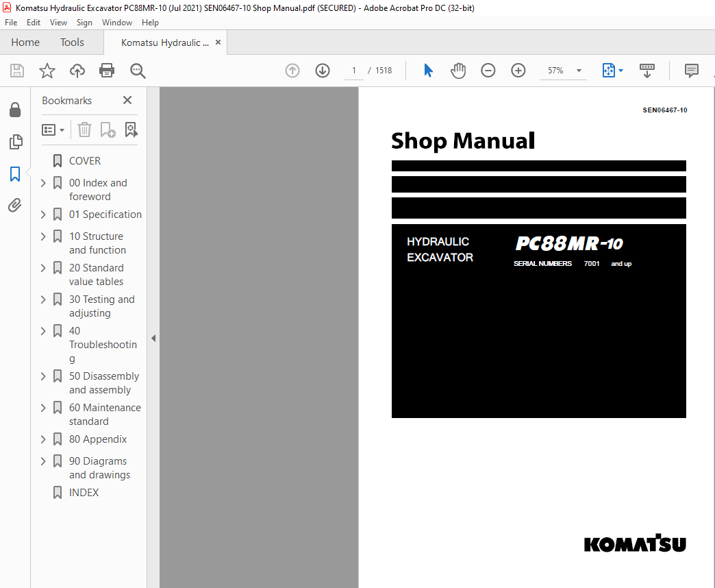
Komatsu PC88MR-10 Hydraulic Excavator Shop Manual SEN06467-10 – PDF DOWNLOAD
Komatsu PC88MR-10 Hydraulic Excavator Shop Manual SEN06467-10 – PDF DOWNLOAD
FILE DETAILS:
Komatsu PC88MR-10 Hydraulic Excavator Shop Manual SEN06467-10 – PDF DOWNLOAD
Language : English
Pages : 1518
Downloadable : Yes
File Type : PDF
Size: 55.8 MB
TABLE OF CONTENTS:
Komatsu PC88MR-10 Hydraulic Excavator Shop Manual SEN06467-10 – PDF DOWNLOAD
COVER 1
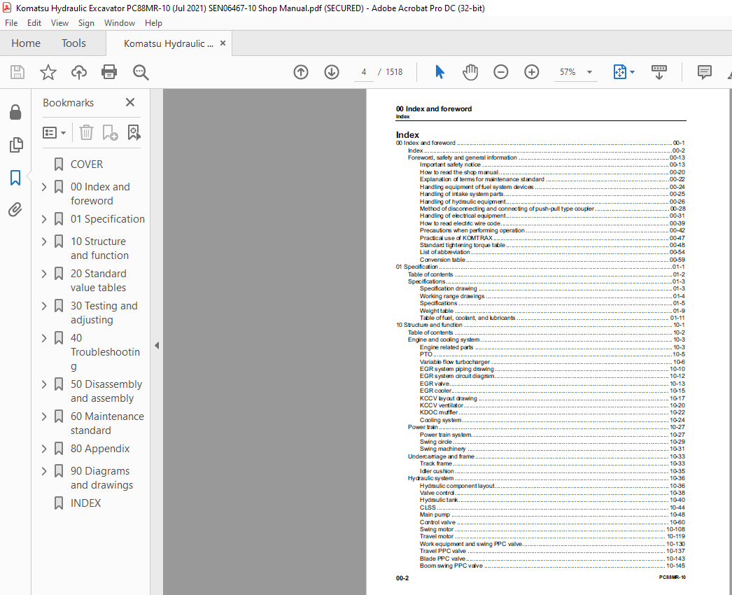
00 Index and foreword 3
Index 4
Foreword, safety and general information 15
Important safety notice 15
How to read the shop manual 22
Explanation of terms for maintenance standard 24
Handling equipment of fuel system devices 26
Handling of intake system parts 27
Handling of hydraulic equipment 28
Method of disconnecting and connecting of push-pull type coupler 30
Handling of electrical equipment 33
How to read electric wire code 41
Precautions when performing operation 44
Practical use of KOMTRAX 49
Standard tightening torque table 50
List of abbreviation 56
Conversion table 61
01 Specification 67
Table of contents 68
Specifications 69
Specification drawing 69
Working range drawings 70
Specifications 71
Weight table 75
Table of fuel, coolant, and lubricants 77
10 Structure and function 79
Table of contents 80
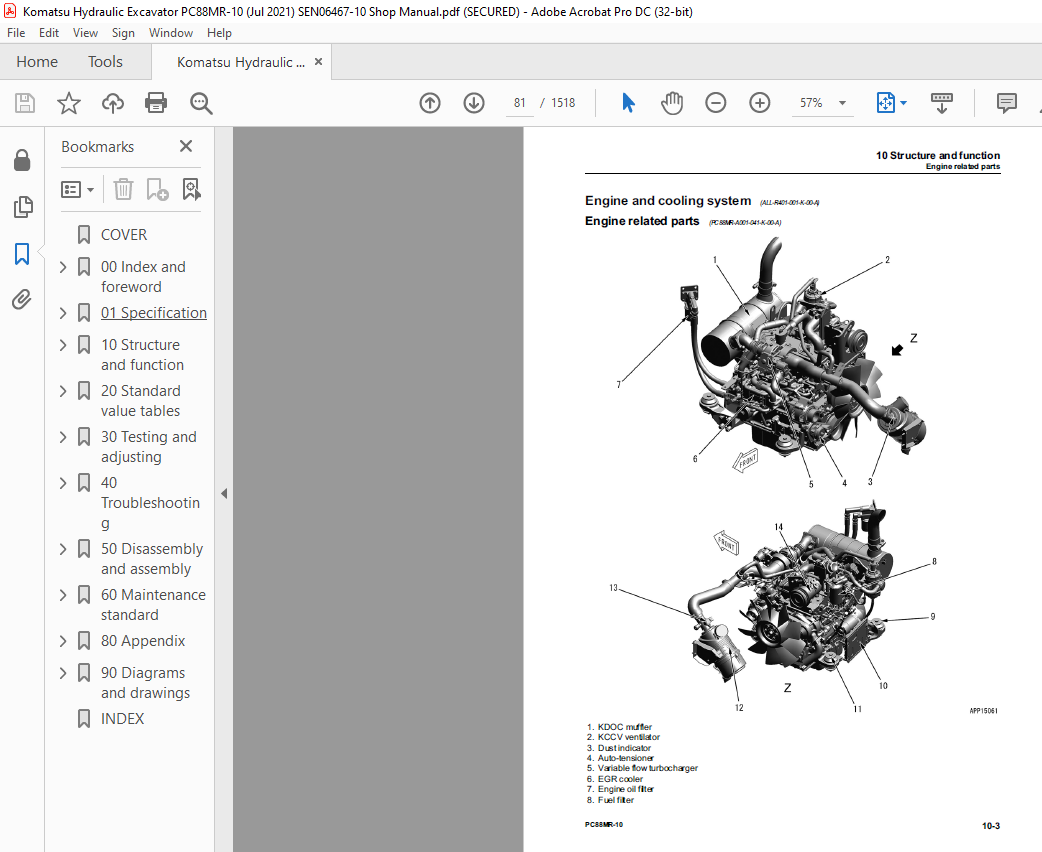
Engine and cooling system 81
Engine related parts 81
PTO 83
Variable flow turbocharger 84
EGR system piping drawing 88
EGR system circuit diagram 90
EGR valve 91
EGR cooler 93
KCCV layout drawing 95
KCCV ventilator 98
KDOC muffler 100
Cooling system 102
Power train 105
Power train system 105
Swing circle 107
Swing machinery 109
Undercarriage and frame 111
Track frame 111
Idler cushion 113
Hydraulic system 114
Hydraulic component layout 114
Valve control 116
Hydraulic tank 118
CLSS 122
Main pump 126
Control valve 138
Swing motor 186
Travel motor 197
Work equipment and swing PPC valve 210
Travel PPC valve 217
Blade PPC valve 223
Boom swing PPC valve 225
Solenoid valve 227
Multi-control valve 231
Anti-drop valve for boom 232
Anti-drop valve for arm 236
Center swivel joint 240
Accumulator 241
Work equipment 243
Work equipment 243
Work equipment shim 244
Bucket play adjustment shim 245
Cab and its attachments 246
Cab mount and cab tipping stopper 246
ROPS cab 248
Electrical system 250
Electrical control system 250
Machine monitor system 294
KOMTRAX system 316
Sensor 318
20 Standard value tables 327
Table of contents 328
Standard service value table 329
Standard value table for engine 329
Standard value table for machine 331
Standard value table for electrical system 347
30 Testing and adjusting 353
Table of contents 354
Related information on testing and adjusting 355
Tools for testing and adjusting 355
Sketch of tools for testing and adjusting 358
Engine and cooling system 360
Testing engine speed 360
Testing exhaust gas color 361
Testing and adjusting valve clearance 362
Testing compression pressure 364
Testing blowby pressure 366
Testing engine oil pressure 367
Visual check inside of EGR valve 368
Clean inside of EGR valve 369
Testing fuel pressure 372
Testing fuel return rate and leakage 373
Bleeding air from fuel system 376
Testing fuel circuit for leakage 378
Handling cylinder cutout mode operation 379
Handling no-injection cranking operation 380
Testing and adjusting air conditioner compressor belt tension 381
Check fan belt, replace 382
Check auto-tensioner, replace 384
Writing compensation values at replacement of injector and engine controller 387
Power train 391
Testing swing circle bearing clearance 391
Undercarriage and frame 392
Testing and adjusting track tension 392
Hydraulic system 393
Releasing remaining pressure from hydraulic circuit 393
Testing and adjusting oil pressure in work equipment and travel circuits 398
Testing and adjusting swing and blade circuit oil pressure 401
Testing oil pressure of control circuit 404
Testing and adjusting oil pressure in pump PC control circuit 405
Testing and adjusting oil pressure in pump LS control circuit 408
Testing outlet pressure of solenoid valve 411
Testing PPC valve outlet pressure 412
Adjusting play of work equipment and swing PPC valves 413
Isolating the parts causing hydraulic drift in work equipment 414
Testing and adjusting travel deviation 415
Testing oil leakage 417
Bleeding air from hydraulic circuit 421
Cab and its attachments 424
Testing, cleaning and lubricating slide door rail and roller 424
Adjusting mirrors 425
Testing and adjusting hood catcher 427
Electrical system 429
Special functions of machine monitor 429
KOMTRAX terminal start-up procedure 477
Adjusting rearview camera angle 481
Handling voltage circuit of engine controller 483
Handling battery disconnect switch 484
Testing diodes 485
Pm clinic 486
Pm Clinic service 486
40 Troubleshooting 495
Table of contents 496
Related information on troubleshooting 502
Troubleshooting points 502
Sequence of events in troubleshooting 504
Checks before troubleshooting 506
Inspection procedure before troubleshooting 508
Preparation for troubleshooting of electrical system 525
Classification and procedures for troubleshooting 530
Symptom and troubleshooting numbers 533
Information in troubleshooting table 536
Troubleshooting method for open circuit in wiring harness of pressure sensor system 538
Connector list and layout 540
Connector contact identification 550
T-branch box and T-branch adapter table 589
Fuse location table 594
Failure codes table 596
Troubleshooting by failure code (Display of code) 603
Failure code [879AKA] A/C Recirc Air Temp Sens Open Circuit 603
Failure code [879AKB] A/C Recirc Air Temp Sens Short 604
Failure code [879BKA] A/C Fresh Air Temp Sens Open Circuit 605
Failure code [879BKB] A/C Fresh Air Temp Sens Short Circuit 606
Failure code [879CKA] Ventilating Sensor Open Circuit 607
Failure code [879CKB] Ventilating Sensor Short Circuit 608
Failure code [879DKZ] Sunlight Sensor Open or Short Circuit 609
Failure code [879EMC] Ventilation Damper Malfunction 610
Failure code [879FMC] Air Mix Damper Malfunction 611
Failure code [879GKX] Refrigerant Press Input Sig Out of Range 612
Failure code [989L00] Engine Controller Lock Caution 1 613
Failure code [989M00] Engine Controller Lock Caution 2 614
Failure code [989N00] Engine Controller Lock Caution 3 615
Failure code [A900FR] Abrupt Engine Stop by Auto Idle Stop 3 616
Failure code [A900N6] Abrupt Engine Stop by Auto Idle Stop 1 617
Failure code [A900NY] Abrupt Engine Stop by Auto Idle Stop 2 618
Failure code [AB00KE] Charge Voltage Low 619
Failure code [B@BAZG] Eng Oil Press Low 621
Failure code [B@BCNS] Eng Water Overheat 622
Failure code [CA115] Eng Ne and Bkup Speed Sens Error 623
Failure code [CA122] Charge Air Pressure Sensor High Error 624
Failure code [CA123] Charge Air Pressure Sensor Low Error 626
Failure code [CA131] Throttle Sensor High Error 628
Failure code [CA132] Throttle Sensor Low Error 630
Failure code [CA144] Coolant Temperature Sensor High Error 632
Failure code [CA145] Coolant Temperature Sensor Low Error 634
Failure code [CA153] Charge Air Temperature Sensor High Error 636
Failure code [CA154] Charge Air Temperature Sensor Low Error 638
Failure code [CA187] Sensor 2 Supply Voltage Low Error 640
Failure code [CA221] Ambient Pressure Sensor High Error 642
Failure code [CA222] Ambient Pressure Sensor Low Error 644
Failure code [CA227] Sensor 2 Supply Voltage High Error 646
Failure code [CA234] Engine Overspeed 647
Failure code [CA238] NE Speed Sensor Supply Voltage Error 648
Failure code [CA239] NE Speed Sensor Supply Voltage High Error 649
Failure code [CA271] PCV1 Short Circuit Error 650
Failure code [CA272] PCV1 Open Circuit Error 651
Failure code [CA322] Injector #1 (L#1) Open or Short Circuit 652
Failure code [CA324] Injector #3 (L#3) Open or Short Circuit 654
Failure code [CA331] Injector #2 (L#2) Open or Short Circuit 656
Failure code [CA332] Injector #4 (L#4) Open or Short Circuit 658
Failure code [CA343] Engine Controller Internal Failure 660
Failure code [CA351] Injectors Drive Circuit Error 661
Failure code [CA352] Sensor1 Supply Voltage Low Error 662
Failure code [CA356] MAF Sensor High Error 664
Failure code [CA357] MAF Sensor Low Error 666
Failure code [CA386] Sensor1 Supply Voltage High Error 668
Failure code [CA435] Engine Oil Pressure SW Error 669
Failure code [CA441] Battery Voltage Low Error 670
Failure code [CA442] Battery Voltage High Error 672
Failure code [CA449] Common Rail Pressure High Error 2 673
Failure code [CA451] Common Rail Pressure Sensor High Error 674
Failure code [CA452] Common Rail Pressure Sensor Low Error 676
Failure code [CA466] KVGT Motor Driver Position Error 678
Failure code [CA515] Rail Pressure Sensor Sup Volt High Error 680
Failure code [CA516] Rail Pressure Sensor Sup Volt Low Error 682
Failure code [CA553] Common Rail Pressure High Error 1 684
Failure code [CA555] Crankcase Pressure High Error 1 685
Failure code [CA556] Crankcase Pressure High Error 2 686
Failure code [CA559] Common Rail Pressure Low Error 1 687
Failure code [CA689] Engine NE Speed Sensor Error 690
Failure code [CA691] Intake Air Temperature Sensor High Error 692
Failure code [CA692] Intake Air Temperature Sensor Low Error 694
Failure code [CA697] Engine Con Internal Temp Sens High Error 696
Failure code [CA698] Engine Con Internal Temp Sens Low Error 697
Failure code [CA731] Engine Backup Speed Sensor Phase Error 698
Failure code [CA778] Engine Backup Speed Sensor Error 700
Failure code [CA1117] Engine Controller Partial Data Lost Error 704
Failure code [CA1695] Sensor 5 Supply Voltage High Error 705
Failure code [CA1696] Sensor 5 Supply Voltage Low Error 706
Failure code [CA1843] Crankcase Pressure Sensor High Error 707
Failure code [CA1844] Crankcase Pressure Sensor Low Error 709
Failure code [CA1896] EGR Valve Stuck Error 711
Failure code [CA1942] Crankcase Pressure Sensor In Range Error 714
Failure code [CA1961] EGR_Motor Driver IC Over Temp Error 715
Failure code [CA2185] Throttle Sensor Supply Voltage High Error 716
Failure code [CA2186] Throttle Sensor Supply Voltage Low Error 718
Failure code [CA2249] Common Rail Pressure Low Error 2 720
Failure code [CA2272] EGR Valve Position Sensor Low Error 721
Failure code [CA2311] IMV Solenoid Error 723
Failure code [CA2349] EGR Valve Solenoid Open Circuit Error 724
Failure code [CA2353] EGR Valve Solenoid Short Circuit Error 726
Failure code [CA2357] EGR Valve Servo Error 728
Failure code [CA2765] Injector Trim Data Mismatch 729
Failure code [CA3419] MAF Sensor Supply Voltage High Error 730
Failure code [CA3421] MAF Sensor Supply Voltage Low Error 732
Failure code [CA3724] EGR/KVGT Motor Driver Power Low Error 734
Failure code [CA3918] KVGT Stuck Error 736
Failure code [CA3919] KVGT Motor Driver IC Over Temp Error 737
Failure code [CA3921] KVGT Servo Error 2 738
Failure code [CA3922] KVGT Motor Driver Open Error 739
Failure code [CA3923] KVGT Motor Driver Short Error 741
Failure code [D110KB] Battery Relay Output Short Circuit 743
Failure code [D19JKZ] Personal Code Relay Open or Short 745
Failure code [D811MC] KOMTRAX Malfunction 748
Failure code [D862KA] GPS Antenna Open Circuit 749
Failure code [D8ALKA] Operating Lamp Open Circuit (KOMTRAX) 750
Failure code [D8ALKB] Operating Lamp Short Circuit (KOMTRAX) 752
Failure code [D8AQKR] CAN 2 Defective Communication (KOMTRAX) 753
Failure code [DA20MC] Pump Controller Malfunction 755
Failure code [DA22KK] Pump Con Solenoid Power Volt Low Error 756
Failure code [DA25KP] 5V Sensor 1 Power Voltage Low Error 758
Failure code [DA29KQ] Model Selection Sig Mismatch (Pump Con) 760
Failure code [DA2LKA] Operating Lamp Open Circuit (Pump Con) 762
Failure code [DA2LKB] Operating Lamp Short Circuit (Pump Con) 764
Failure code [DA2QKR] CAN 2 Defective Communication (Pump Con) 765
Failure code [DA2RKR] CAN 1 Defective Communication (Pump Con) 767
Failure code [DAF0MB] Monitor ROM Abnormality 768
Failure code [DAF0MC] Monitor Malfunction 769
Failure code [DAF8KB] Camera Power Supply Short Circuit 770
Failure code [DAF9KQ] Model Selection Signal Mismatch (Monitor) 771
Failure code [DAFGMC] GPS Module Malfunction 772
Failure code [DAFLKA] Operating Lamp Open Circuit (Monitor) 773
Failure code [DAFLKB] Operating Lamp Short Circuit (Monitor) 775
Failure code [DAFQKR] CAN 2 Defective Communication (Monitor) 776
Failure code [DAZ9KQ] Model Selection Sig Mismatch (A/C) 777
Failure code [DAZQKR] CAN2 Defective Communication (A/C ECU) 778
Failure code [DB2QKR] CAN2 Defective Communication (Engine Con) 782
Failure code [DB2RKR] CAN1 Defective Communication (Engine Con) 786
Failure code [DDNRKA] WE Lever Lock SW Open Circuit 790
Failure code [DDNRKY] WE Lever Lock SW Short Circuit 792
Failure code [DDNS00] Lock Lever Auto Lock Release SW On 794
Failure code [DGH2KB] Hydraulic Oil Temp Sensor Ground Fault 796
Failure code [DHPAMA] Front Pump Press Sens Defective Function 798
Failure code [DHS3MA] Arm IN PPC Press Sensor Def Function 800
Failure code [DHS4MA] Bucket CURL PPC Press Sens Def Function 802
Failure code [DHS5MA] Travel PPC Sensor Abnormality 804
Failure code [DHS8MA] Boom Raise PPC Press Sens Def Function 806
Failure code [DHS9MA] Boom Lower PPC Press Sens Def Function 808
Failure code [DHSAMA] Swing Right PPC Press Sens Def Function 810
Failure code [DHSBMA] Swing Left PPC Press Sensor Def Function 812
Failure code [DHSCMA] Arm OUT PPC Press Sens Def Function 814
Failure code [DHSDMA] Bucket DUMP PPC Press Sens Def Function 816
Failure code [DHSPMA] Boom Swing LH PPC Press Sensor Abnormality 818
Failure code [DHSQMA] Boom Swing RH PPC Press Sensor Abnormality 820
Failure code [DKULKA] PPC Lock Relay Open Circuit 822
Failure code [DKULKB] PPC Lock Relay Short Circuit 824
Failure code [DKULKY] PPC Lock Relay Hot Short Circuit 826
Failure code [DV20KB] Travel Alarm Short Circuit 828
Failure code [DW43KA] Travel Speed Solenoid Open Circuit 830
Failure code [DW43KB] Travel Speed Solenoid Short Circuit 832
Failure code [DW43KY] Travel Speed Sol Hot Short Circuit 834
Failure code [DW45KA] Swing Parking Brake Solenoid Open Circuit 835
Failure code [DW45KB] Swing Parking Brake Solenoid Short Circuit 838
Failure code [DW45KY] Swing Brake Sol Hot Short Circuit 840
Failure code [DW4CKY] PPC lock Sol Hot Short Circuit 842
Failure code [DWJ0KA] Merge-divider Sol Open Circuit 844
Failure code [DWJ0KB] Merge-divider Sol Short Circuit 846
Failure code [DWJ0KY] Merge-divider Sol Short Circuit 848
Failure code [DXA8KA] Front Pump PC-EPC Solenoid Open Circuit 849
Failure code [DXA8KB] Front Pump PC-EPC Solenoid Short Circuit 851
Failure code [DXE7KA] Attachment Flow Regulating EPC 2 Solenoid Open Circuit 853
Failure code [DXE7KB] Att Flow Regulating EPC 2 Short Circuit 855
Failure code [DXE7KY] Attachment Flow Regulating EPC 2 Solenoid Hot Short Circuit 857
Failure code [DXEAKA] Att Flow Regulating EPC 5 Open Circuit 859
Failure code [DXEAKB] Att Flow Regulating EPC 5 Short Circuit 861
Failure code [DXEAKY] Service Current EPC5 Hot Short Circuit 863
Failure code [DY20KA] Wiper Motor Open Circuit 865
Failure code [DY20MA] Wiper Motor Defective Function 867
Failure code [DY2CKB] Washer Motor Short Circuit 869
Failure code [DY2DKB] Wiper Motor (Normal) Short Circuit 871
Failure code [DY2EKB] Wiper Motor (Reverse) Short Circuit 873
Troubleshooting of electrical system (E-mode) 875
E-1 Engine does not start (Engine does not crank) 875
E-2 Manual preheating system does not work 881
E-3 While preheating is working, preheating monitor does not light up 884
E-4 When starting switch is turned to ON position, machine monitor displays nothing 886
E-5 Engine coolant temperature monitor lights up in white while engine is running 889
E-6 Hydraulic oil temperature monitor lights up in white while engine is running 890
E-7 Charge level monitor lights up while engine is running 891
E-8 Fuel level monitor lights up in red while engine is running 892
E-9 Engine coolant temperature monitor lights up in red while engine is running 893
E-10 Hydraulic oil temperature monitor lights up in red while engine is running 894
E-11 Engine oil pressure monitor lights up in red while engine is running 895
E-12 Fuel gauge display does not move from minimum or maximum 896
E-13 Fuel gauge indicates incorrect amount (indicates neither full nor empty) 897
E-14 Engine coolant temperature gauge display does not move from minimum or maximum 898
E-15 Engine coolant temperature gauge indicates incorrect temperature (indicates neither full nor empty) 899
E-16 Hydraulic oil temperature gauge does not move from minimum or maximum 900
E-17 Hydraulic oil temperature gauge indicates incorrect temperature (indicates neither full nor empty) 902
E-18 Some areas of machine monitor screen are not displayed 903
E-19 Function switch does not work 904
E-20 Automatic warm-up system does not operate (in cold season) 905
E-21 Auto-deceleration monitor does not light up, or does not go out, while auto-deceleration switch is operated 906
E-22 Auto-deceleration function does not operate or is not canceled while lever is operated 907
E-23 Working mode selection screen is not displayed while working mode selector switch is operated 909
E-24 Setting of engine and hydraulic pump is not changed while working mode is changed 910
E-25 Travel speed monitor does not change when travel speed switch is operated 911
E-26 Travel speed does not change while travel speed selection is changed 912
E-27 Alarm buzzer does not stop sounding 913
E-28 Service meter is not displayed, while starting switch is in OFF position 914
E-29 Service mode cannot be selected 915
E-30 Any of work equipment, swing and travel does not work 916
E-31 Any of work equipment, swing and travel cannot be locked 918
E-32 Upper structure does not swing while swing parking brake cancel switch is set to CANCEL position 920
E-33 Swing brake does not operate while swing parking brake cancel switch is set to NORMAL position 922
E-34 Work equipment does not operate while lock lever automatic release switch is in release position 924
E-35 Alarm does not sound during travel 926
E-36 Alarm does not stop sounding while machine is stopped 927
E-37 Horn does not sound 928
E-38 Horn does not stop sounding 930
E-39 Wiper monitor does not light up, or does not go out, while wiper switch is operated 931
E-40 Wiper does not operate while wiper switch is operated 932
E-41 Window washer does not operate while window washer switch is operated 934
E-42 Boom LOWER is not displayed correctly with monitoring function 935
E-43 Arm OUT is not displayed correctly with monitoring function 936
E-44 Arm IN is not displayed correctly with monitoring function 937
E-45 Boom RAISE is not displayed correctly with monitoring function 938
E-46 Bucket CURL is not displayed correctly with monitoring function 939
E-47 Bucket DUMP is not displayed correctly with monitoring function 940
E-48 Boom swing left is not displayed correctly with monitoring function 941
E-49 Boom swing right is not displayed correctly with monitoring function 942
E-50 Swing is not displayed correctly with monitoring function 943
E-51 Travel is not displayed correctly with monitoring function 944
E-52 Blade RAISE ON is not displayed correctly with monitoring function 945
E-53 Blade LOWER ON is not displayed correctly with monitoring function 947
E-54 KOMTRAX system does not operate normally 949
Troubleshooting of hydraulic and mechanical system (H-mode) 951
Information described in troubleshooting table (H-mode) 951
System chart of hydraulic and mechanical systems 952
Failure mode and cause table 954
H-1 All of work equipments, swing and travel operations lack speed or power 962
H-2 Engine speed drops significantly or engine stalls 964
H-3 Any of work equipment, swing and travel does not work 965
H-4 Unusual sound is heard from around hydraulic pump 966
H-5 Fine control performance or response is poor 967
H-6 Boom speed or power is low 968
H-7 Arm speed or power is low 971
H-8 Bucket speed or power is low 973
H-9 Boom swing speed or power is low 975
H-10 Blade speed or power is low 977
H-11 Work equipment does not move in single operation 979
H-12 Hydraulic drift of boom is large 980
H-13 Hydraulic drift of arm is large 981
H-14 Hydraulic drift of bucket is large 982
H-15 Hydraulic drift of blade is large 983
H-16 Time lag of work equipment is large 984
H-17 In combined operation of work equipment , equipment having heavier load moves slower 986
H-18 In combined operation of swing and boom RAISE, boom rising speed is low 987
H-19 In combined operation of work equipment or swing and travel, travel speed drops largely 988
H-20 Machine does not travel straight 990
H-21 Travel speed is slow 992
H-22 Machine is hard to steer or travel power is low 994
H-23 Travel speed does not change, or travel speed is too slow or fast 997
H-24 One of tracks does not run 998
H-25 Upper structure does not swing to the right or left 1000
H-26 Upper structure swing only to the right or left 1001
H-27 Swing acceleration or swing speed is low in both directions (right and left) 1002
H-28 Swing acceleration performance is poor or swing speed is slow in only one direction 1003
H-29 Upper structure overruns excessively when it stops swinging (both right and left) 1004
H-30 Upper structure overruns excessively when it stops swinging (either right or left) 1005
H-31 Shock is large when upper structure stops swinging 1006
H-32 Large unusual noise is heard when upper structure stops swinging 1007
H-33 Swing drift on a slope is large while swing parking brake is applied 1008
H-34 Swing drift on a slope is large while swing parking brake is released 1009
H-35 Oil flow in attachment circuit cannot be controlled 1010
Troubleshooting of engine (S-mode) 1011
Information mentioned in troubleshooting table (S mode) 1011
S-1 Engine does not crank when starting switch is turned to START position 1012
S-2 Engine cranks but no exhaust smoke comes out 1013
S-3 Fuel is being injected but engine does not start (misfiring: engine cranks but does not start) 1014
S-4 Engine startability is poor 1015
S-5 Engine does not pick up smoothly 1017
S-6 Engine stops during operation 1019
S-7 Engine runs rough or is unstable 1021
S-8 Engine lacks power 1022
S-9 Exhaust smoke is black 1024
S-10 Engine oil consumption is excessive 1026
S-11 Oil becomes contaminated quickly 1027
S-12 Fuel consumption is excessive 1028
S-13 Oil is in coolant (or coolant spurts or coolant level goes down) 1029
S-14 Oil pressure drops 1030
S-15 Fuel mixes into engine oil 1031
S-16 Water mixes into engine oil (milky) 1032
S-17 Coolant temperature rises too high (overheating) 1033
S-18 Unusual noise is heard 1034
S-19 Vibration is excessive 1035
S-20 Air cannot be bled from fuel circuit 1036
50 Disassembly and assembly 1037
Table of contents 1038
Related information on disassembly and assembly 1040
How to read this manual 1040
Coating materials list 1042
Special tools list 1046
Sketches of special tools 1051
Engine and cooling system 1053
Removal and installation of supply pump assembly 1053
Removal and installation of injector assembly 1056
Removal and installation of cylinder head assembly 1063
Removal and installation of radiator assembly 1075
Removal and installation of hydraulic oil cooler assembly 1079
Removal and installation of aftercooler assembly 1082
Removal and installation of engine and main pump assembly 1085
Removal and installation of engine front oil seal 1093
Removal and installation of engine rear oil seal 1094
Removal and installation of fuel cooler assembly 1096
Removal and installation of fuel tank assembly 1097
Removal and installation of engine hood assembly 1099
Removal and installation of KDOC muffler 1100
Removal and installation of KCCV ventilator 1103
Removal and installation of air cleaner assembly 1105
Removal and installation of EGR (Exhaust Gas Recirculation) cooler assembly 1107
Removal and installation of EGR (Exhaust Gas Recirculation) valve assembly 1109
Removal and installation of fan belt 1110
Power train system 1112
Removal and installation of travel motor and final drive assembly 1112
Disassembly and assembly of travel motor and final drive assembly (Applicable machine: #7001 to 8864) 1114
Disassembly and assembly of travel motor and final drive assembly (Applicable machine: #8865 and up) 1162
Removal and installation of swing motor and swing machinery assembly 1213
Disassembly and assembly of swing machinery assembly 1215
Removal and installation of swing circle assembly 1223
Undercarriage and frame 1224
Separation and connection of track 1224
Removal and installation of sprocket 1225
Removal and installation of idler and idler cushion assembly 1226
Disassembly and assembly of idler assembly 1227
Disassembly and assembly of idler cushion assembly 1230
Disassembly and assembly of track roller assembly 1233
Removal and installation of revolving frame assembly 1236
Removal and installation of counterweight assembly [For machines with additional counterweight] 1238
Hydraulic system 1240
Removal and installation of center swivel joint assembly 1240
Disassembly and assembly of center swivel joint assembly 1242
Removal and installation of hydraulic tank assembly 1243
Removal and installation of main pump assembly 1246
Removal and installation of control valve assembly 1250
Disassembly and assembly of control valve assembly 1254
Disassembly and assembly of work equipment PPC valve assembly 1257
Disassembly and assembly of travel PPC valve assembly 1259
Disassembly and assembly of work equipment cylinder assembly 1260
Work equipment 1264
Removal and installation of work equipment assembly 1264
Removal and installation of boom swing bracket 1267
Removal and installation of anti-drop valve for boom assembly 1268
Removal and installation of anti-drop valve for arm assembly 1271
Disassembly and assembly of anti-drop valve assembly 1274
Removal and installation of blade assembly 1275
Cab and its attachments 1277
Removal and installation of operator’s cab assembly 1277
Removal and installation of operator’s cab door 1281
Removal and installation of operator’s cab glass (adhered glass) 1284
Removal and installation of front window assembly 1295
Removal and installation of floor frame assembly 1296
Removal and installation of air conditioner unit assembly 1301
Removal and installation of air conditioner compressor assembly 1306
Removal and installation of air conditioner condenser assembly 1308
Removal and installation of operator’s seat 1310
Removal and installation of seat belt 1311
Removal and installation of front wiper assembly 1312
Electrical system 1319
Removal and installation of starting motor assembly 1319
Removal and installation of engine controller assembly 1320
Removal and installation of pump controller assembly 1321
Removal and installation of machine monitor assembly 1322
Removal and installation of mass air flow and temperature sensor 1324
Removal and installation of KOMTRAX terminal assembly 1325
60 Maintenance standard 1327
Table of contents 1328
Engine and cooling system 1329
Engine mount 1329
PTO 1330
Cooling system 1331
Power train system 1333
Swing circle 1333
Swing machinery 1335
Sprocket 1337
Undercarriage and frame 1338
Track frame 1338
Idler cushion 1339
Idler 1340
Track roller 1341
Carrier roller 1342
Track shoe 1343
Hydraulic system 1349
Hydraulic tank 1349
Main pump 1350
Control valve 1354
Swing motor 1363
Travel motor 1365
PPC valve 1366
Work equipment and swing PPC valve 1366
Travel PPC valve 1369
Blade PPC valve 1371
Boom swing PPC valve 1373
Solenoid valve 1375
Anti-drop valve for boom 1377
Anti-drop valve for arm 1379
Center swivel joint 1381
Cab and its attachments 1382
Cab mount and cab tipping stopper 1382
Work equipment 1383
Work equipment 1383
Boom cylinder 1394
Arm cylinder 1395
Bucket cylinder 1396
Boom swing cylinder 1397
Blade cylinder 1398
80 Appendix 1399
Table of contents 1400
Air conditioner components 1401
Precautions for refrigerant 1401
Air conditioner component 1402
Configuration and function of refrigeration cycle 1405
Outline of refrigeration cycle 1406
Air conditioner unit 1408
Dual pressure switch 1413
Air conditioner controller 1414
Compressor 1415
Condenser 1416
Sunlight sensor 1418
Outer temperature sensor (outside air temperature sensor) 1419
Procedure for testing and troubleshooting 1420
Circuit diagram and arrangement of connector pins 1422
System diagram 1424
Input and output signals of the air conditioner controller 1425
Air conditioner unit 1427
Parts and connectors layout 1429
Testing air leakage (duct) 1435
Testing with self-diagnosis function 1437
Testing vent (mode) changeover 1440
Testing FRESH/RECIRC air changeover 1441
Testing sunlight sensor 1442
Testing (dual) pressure switch for refrigerant 1443
Testing relays 1445
Troubleshooting chart 1 1446
Troubleshooting chart 2 1447
Information in troubleshooting table 1450
Failure code list related to air conditioner 1451
Failure code [879AKA] A/C Recirc Air Temp Sens Open Circuit 1452
Failure code [879AKB] A/C Recirc Air Temp Sens Short 1453
Failure code [879BKA] A/C Fresh Air Temp Sens Open Circuit 1454
Failure code [879BKB] A/C Fresh Air Temp Sens Short Circuit 1456
Failure code [879CKA] Ventilating Sensor Open Circuit 1458
Failure code [879CKB] Ventilating Sensor Short Circuit 1459
Failure code [879DKZ] Sunlight Sensor Open or Short Circuit 1460
Failure code [879EMC] Ventilation Damper Malfunction 1462
Failure code [879FMC] Air Mix Damper Malfunction 1463
Failure code [879GKX] Refrigerant Press Input Sig Out of Range 1464
A-1 Troubleshooting for power supply system (Air conditioner does not operate) 1465
A-2 Troubleshooting for compressor and refrigerant system (Air is not cooled) 1467
A-3 Troubleshooting for blower motor system (No air comes out or air flow is abnormal) 1470
A-4 Troubleshooting for FRESH/RECIRC air changeover 1472
Troubleshooting with gauge pressure 1474
Connection of service tool 1477
Precautions for disconnecting and connecting refrigerant piping 1479
Handling of compressor oil 1481
90 Diagrams and drawings 1483
Table of contents 1484
Hydraulic circuit diagram 1485
Symbols in hydraulic circuit diagram 1485
Hydraulic circuit diagram 1489
Electric circuit diagram 1493
Symbols in electric circuit diagram 1493
Electrical circuit diagram 1497
Electrical circuit diagram of air conditioner unit 1507
INDEX 1509
DESCRIPTION:
Komatsu PC88MR-10 Hydraulic Excavator Shop Manual SEN06467-10 – PDF DOWNLOAD
SERIAL NUMBERS 7001 and up
Foreword, safety and general information (ALL-0370-001-A-00-A)
Important safety notice (ALL-1120-012-A-01-A)
• Appropriate servicing and repair are extremely important to ensure safe operation of the machine. The
shop manual describes the effective and safe servicing and repair methods recommended by Komatsu.
Some of these methods require the use of the special tools designed by Komatsu for the specific purpose.
• The symbol markkis used for such matters that require special cautions during the work. The work
indicated by the caution mark should be performed according to the instructions with special attention to
the cautions. Should hazardous situation occur or be anticipated during such work, be sure to keep safe
first and take every necessary measure.
Safety points:
• Good arrangement
• Correct work clothes
• Observance of work standard
• Practice of making and checking signals
• Prohibition of operation and handling by
unlicensed workers
• Safety check before starting work
• Wearing protective goggles (for cleaning or
grinding work)
• Wearing shielding goggles and protectors (for
welding work)
• Good physical condition and preparation
• Precautions against work which you are not
used to or you are used to too much
General precautions:
• Before performing any greasing or repairs, read all the safety labels stuck to the machine. For the locations of the safety labels and detailed explanation of precautions, see the operation and maintenance manual.• Locate a place in the repair workshop to keep the tools and removed parts. Always keep the tools and parts in their correct places. Always keep the work area clean and make sure that there is no dirt, water or oil on the floor. Smoke only in the areas provided for smoking. Never smoke while working.• When performing any work, always wear the safety shoes and helmet. Do not wear loose work cloths, or clothes with buttons missing. 1. Always wear the protective eyeglasses when hitting parts with a hammer. 2. Always wear the protective eyeglasses when grinding parts with a grinder, etc.• When performing any work with 2 or more workers, always agree on the working procedure before starting. While working, always keep conversations of the work between your fellow workers and your self on any step of the work. During the work, hang the warning tag of “UNDER WORKING” in the operator’s compartment.• Only qualified workers must perform the work and operation which require license or qualification.• Keep the tools in good condition. And learn the correct way to use the tools, and use the proper ones among them. Before starting the work, thoroughly check the tools, lift truck, service vehicle, etc.• If welding repairs is required, always have a trained and experienced welder with good knowledge of welding perform the work. When performing welding work, always wear welding gloves, apron, shielding goggles, cap, etc.• Before starting work, warm up your body thoroughly to start work under good condition.• Avoid continuing work for long hours and take rests with proper intervals to keep your body in good condition. Take a rest in a specified safe place.
Preparation:
• Before adding oil or making any repairs, place the machine on a firm and level ground, and apply the parking brake and chock the wheels or tracks to prevent the machine from moving.• Before starting work, lower the work equipment (blade, ripper, bucket, etc.) to the ground. If it is not possible to lower the equipment to the ground, insert the lock pin or use blocks to prevent the work equipment from falling. And be sure to lock all the work equipment control levers and hang a warning tag on them.• When performing the disassembling or assembling work, support the machine securely with blocks, jacks, or stands before starting the work.• Remove all of mud and oil from the steps or other places used to get on and off the machine completely. Always use the handrails, ladders of steps when getting on or off the machine.
IMAGES PREVIEW OF THE MANUAL:
Komatsu PC88MR-10 Hydraulic Excavator Shop Manual SEN06467-10 – PDF DOWNLOAD
More products