$38
Komatsu Perkins 1000 Series Diesel Engine Shop Manual SEBE1006600 – PDF DOWNLOAD
Komatsu Perkins 1000 Series Diesel Engine Shop Manual SEBE1006600 – PDF DOWNLOAD
FILE DETAILS:
Komatsu Perkins 1000 Series Diesel Engine Shop Manual SEBE1006600 – PDF DOWNLOAD
Language : English
Pages : 170
Downloadable : Yes
File Type : PDF
Size: 20.8 MB
IMAGES PREVIEW OF THE MANUAL:
DESCRIPTION:
Komatsu Perkins 1000 Series Diesel Engine Shop Manual SEBE1006600 – PDF DOWNLOAD
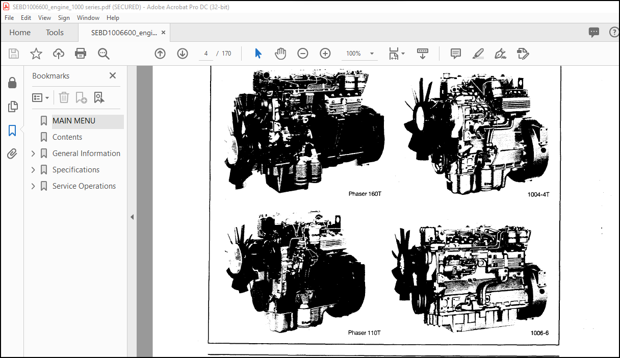
The Komatsu Perkins 1000 Series Diesel Engine Shop Manual SEBE1006600 is a comprehensive guide that provides detailed information on the maintenance, repair, and overhaul of the Komatsu Perkins 1000 series diesel engines. These engines are commonly used in a wide range of equipment, including generators, pumps, and construction machinery.
- The manual is organized into several sections, each covering a different aspect of the engine. The first section provides an overview of the engine and its components, including the specifications and performance data. This section also includes a table of contents, a list of illustrations, and a list of symbols and abbreviations used throughout the manual.
- The second section of the manual covers engine inspection and measurement procedures. This section provides step-by-step instructions for checking and measuring various components of the engine, including the cylinder block, crankshaft, and connecting rods. The manual includes detailed illustrations to help the reader understand the procedures.
- The third section covers engine disassembly and assembly procedures. This section provides instructions for removing and installing various components of the engine, including the cylinder head, pistons, and crankshaft. The manual also includes torque specifications for each component.
- The fourth section covers engine testing and adjusting procedures. This section provides instructions for testing and adjusting various components of the engine, including the fuel injection system, the turbocharger, and the valve clearance. The manual includes detailed illustrations to help the reader understand the procedures.
- The fifth section covers engine maintenance procedures, including routine maintenance and inspections. This section provides instructions for maintaining the engine to ensure its continued performance and longevity.
- The sixth section covers engine troubleshooting and diagnosis procedures. This section provides instructions for diagnosing and troubleshooting various engine problems, including starting problems, low power output, and excessive smoke. The manual includes a troubleshooting chart and detailed illustrations to help the reader diagnose and fix the problem.
- Overall, the Komatsu Perkins 1000 Series Diesel Engine Shop Manual SEBE1006600 is a comprehensive guide that provides detailed information on the maintenance, repair, and overhaul of the Komatsu Perkins 1000 series diesel engines. It is an essential tool for anyone working on or maintaining these engines. The manual is available in print or digital formats, making it a convenient and accessible resource for mechanics and technicians.
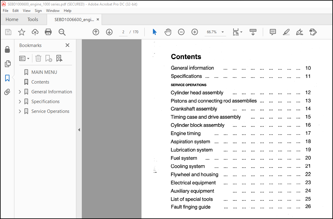
TABLE OF CONTENTS:
Komatsu Perkins 1000 Series Diesel Engine Shop Manual SEBE1006600 – PDF DOWNLOAD
MAIN MENU………………………………………………………………………. 1
Contents……………………………………………………………………….. 2
General Information……………………………………………………………… 3
Introduction………………………………………………………………… 4
Engine identification………………………………………………………… 5
Safety precautions…………………………………………………………… 6
Asbestos joints……………………………………………………………… 7
Specifications………………………………………………………………….. 8
Weight table………………………………………………………………… 9
Recommended torque tensions…………………………………………………… 10
Cylinder head assembly……………………………………………………. 11
Piston and connecting rod assemblies……………………………………….. 11
Crankshaft assembly………………………………………………………. 11
Timing case and drive assembly…………………………………………….. 11
Aspiration system………………………………………………………… 11
Lubrication system……………………………………………………….. 11
Fuel system……………………………………………………………… 11
Cooling system…………………………………………………………… 11
Flywheel and housing……………………………………………………… 12
Electrical equipment……………………………………………………… 12
Auxiliary equipment………………………………………………………. 12
Data and dimensions………………………………………………………….. 13
Introduction…………………………………………………………….. 14
Cylinder head assembly……………………………………………………. 14
Pistons and connecting rods……………………………………………….. 17
Crankshaft assembly………………………………………………………. 19
Timing case and drive assembly…………………………………………….. 23
Cylinder block assembly…………………………………………………… 24
Aspiration system………………………………………………………… 24
Lubrication system……………………………………………………….. 25
Fuel system……………………………………………………………… 26
Cooling system…………………………………………………………… 28
Flywheel and housing……………………………………………………… 28
Electrical equipment……………………………………………………… 29
Auxiliary equipment………………………………………………………. 30
Service Operations………………………………………………………………. 31
Cylinder head assembly……………………………………………………….. 31
General description………………………………………………………. 32
Rocker cover…………………………………………………………….. 33
12A-01 To remove and to fit …………………………………………… 33
Rocker assembly………………………………………………………….. 34
12A-02 To remove and to fit …………………………………………… 34
12A-03 To dismantle and to assemble ……………………………………. 34
12A-04 To inspect and to correct ………………………………………. 34
Valve tip clearances……………………………………………………… 35
12A-05 To check and to adjust …………………………………………. 35
Valve springs……………………………………………………………. 36
12A-06 To change the valve springs (with cylinder head fitted) ……………. 36
Cylinder head assembly……………………………………………………. 37
12A-07 To remove and to fit …………………………………………… 37
Valves and valve springs………………………………………………….. 40
12A-08 To remove and to fit …………………………………………… 40
12A-09 To inspect and to correct ………………………………………. 41
Valve guides…………………………………………………………….. 42
12A-10 To inspect ……………………………………………………. 42
12A-11 To remove and to fit …………………………………………… 42
Cylinder head……………………………………………………………. 43
12A-12 To inspect and to correct ………………………………………. 43
12A-13 To correct a valve seat with a valve seat cutter ………………….. 43
12A-14 To fit valve seat inserts ………………………………………. 44
Piston and connecting rod assemblies…………………………………………… 45
General description………………………………………………………. 46
Big end bearing………………………………………………………….. 47
13A-01 To remove and to fit …………………………………………… 47
13A-02 To inspect ……………………………………………………. 47
Piston and connecting rod assembly…………………………………………. 48
13A-03 To remove and to fit …………………………………………… 48
Piston rings…………………………………………………………….. 50
13A-04 To remove and to fit …………………………………………… 50
Piston and connecting rod assembly…………………………………………. 51
13A-05 To dismantle and to assemble ……………………………………. 51
Piston and rings…………………………………………………………. 52
13A-06 To inspect ……………………………………………………. 52
Connecting rod…………………………………………………………… 52
13A-07 To inspect ……………………………………………………. 52
Small end bush…………………………………………………………… 53
13A-08 To remove and to fit …………………………………………… 53
Piston cooling jets………………………………………………………. 53
13A-09 To remove and to fit …………………………………………… 53
13A-10 To check the jet alignment ……………………………………… 53
Crankshaft assembly………………………………………………………….. 54
General description………………………………………………………. 55
Crankshaft pulley………………………………………………………… 56
14A-01A To remove and to fit – engine types AA, AB, AC and AD …………….. 56
14A-01B To remove and to fit – engine types YA, YB, YC and YD …………….. 56
Rear oil seal assembly……………………………………………………. 57
14A-02 To remove and to fit …………………………………………… 57
14A-03 To renew the rear oil seal ……………………………………… 57
Thrust washers…………………………………………………………… 58
14A-04 To check crankshaft end-float …………………………………… 58
14A-05 To remove and to fit …………………………………………… 58
Main bearing…………………………………………………………….. 59
14A-06 To remove and to fit (with the crankshaft in position) …………….. 59
Crankshaft………………………………………………………………. 60
14A-08 To remove and to fit …………………………………………… 60
14A-09 To inspect ……………………………………………………. 61
Balancer unit……………………………………………………………. 62
14A-10 To remove and to fit …………………………………………… 62
14A-11 To dismantle and to assemble ……………………………………. 63
14A-12 To inspect ……………………………………………………. 65
14A-13 To remove and to fit the needle roller bearings for the drive shaft …. 66
14A-14 To remove and to fit the bushes for the balance weights ……………. 66
Timing case and drive assembly ……………………………………………….. 67
General description………………………………………………………. 68
Timing case cover………………………………………………………… 69
15A-01 To remove and to fit …………………………………………… 69
Front oil seal…………………………………………………………… 70
15A-02 To remove and to fit …………………………………………… 70
Idler gear and hub……………………………………………………….. 71
15A-03 To remove and to fit …………………………………………… 71
Fuel pump gear…………………………………………………………… 72
To remove and to fit 15A-04……………………………………………. 72
Camshaft gear……………………………………………………………. 73
15A-05 To remove and to fit …………………………………………… 73
Crankshaft gear …………………………………………………………. 74
15A-06 To remove and to fit …………………………………………… 74
Timing case……………………………………………………………… 75
15A-07 To remove and to fit……………………………………………. 75
Camshaft and tappets……………………………………………………… 76
15A-08 To remove and to fit …………………………………………… 76
Cylinder block assembly………………………………………………………. 78
General description………………………………………………………. 79
Cylinder block…………………………………………………………… 80
16A-01 To dismantle and to assemble ……………………………………. 80
16A-02 To inspect ……………………………………………………. 80
Cylinder liner…………………………………………………………… 81
16A-03 To inspect ……………………………………………………. 81
16A-04 To remove glaze from the bore …………………………………… 81
16A-05 To remove and to fit …………………………………………… 82
Engine timing……………………………………………………………….. 84
Engines fitted with Bosch fuel injection pumps………………………………. 85
General description ………………………………………………….. 86
17A-01 To set number 1 piston to TDC on the compression stroke ………… 87
17A-02 To check the valve timing …………………………………… 88
17A-03 To check the timing of the fuel injection pump ………………… 89
17A-04 To check the timing mark of the fuel injection pump ……………. 90
17A-05 To check the engine timing mark ……………………………… 91
Engines fitted with CAV fuel injection pumps………………………………… 92
General description…………………………………………………… 93
17B-01 To set number 1 piston to TDC on the compression stroke ………… 94
17B-02 To check the valve timing …………………………………… 95
17B-03 To check the timing of the fuel injection pump ………………… 95
17B-04 To check the timing mark of the fuel injection pump ……………. 96
17B-05 To check the engine timing mark ……………………………… 97
Aspiration system……………………………………………………………. 98
General description………………………………………………………. 99
Turbocharger……………………………………………………………..100
18A-01 To remove and to fit ……………………………………………100
To clean the impeller and the compressor casing…………………………..101
Lubrication system……………………………………………………………102
General description……………………………………………………….103
Filter canister…………………………………………………………..104
19A-01 To renew ………………………………………………………104
Filter head………………………………………………………………104
19A-02 To remove and to fit ……………………………………………104
Sump…………………………………………………………………….105
19A-03 To remove and to fit ……………………………………………105
Oil strainer and suction pipe………………………………………………105
19A-04 To remove and to fit ……………………………………………105
19A-05 To inspect and to correct ……………………………………….105
Lubricating oil pump………………………………………………………106
19A-06 To remove and to fit ……………………………………………106
19A-07 To inspect …………………………………………………….107
Relief valve……………………………………………………………..108
19A-08 To remove and to fit ……………………………………………108
19A-09 To dismantle and to assemble …………………………………….108
19A-10 To inspect …………………………………………………….108
Fuel system………………………………………………………………….109
General description……………………………………………………….110
Fuel filter………………………………………………………………111
20A-01 To remove and to fit ……………………………………………111
Atomisers………………………………………………………………..111
Atomiser fault………………………………………………………..111
20A-02 To remove and to fit ……………………………………………111
Fuel lift pump……………………………………………………………112
20A-03 To remove and to fit ……………………………………………112
20A-04 To dismantle and to assemble …………………………………….112
20A-05 To test ……………………………………………………….113
Fuel injection pump……………………………………………………….114
20A-06A To remove and to fit – Bosch pump ……………………………….114
20A-06B To remove and to fit – CAV pump …………………………………115
20A-07A To adjust – Bosch pump …………………………………………115
20A-07B To adjust – CAV pump …………………………………………..115
Fuel System………………………………………………………………116
20A-08A To eliminate air from the fuel system – Bosch pump ………………..116
20A-08B To eliminate air from the fuel system – CAV pump ………………….117
Cooling system……………………………………………………………….118
General description……………………………………………………….119
Thermostats………………………………………………………………120
21A-01 To remove and to fit ……………………………………………120
To test………………………………………………………………120
Water pump……………………………………………………………….121
21A-02 To remove and to fit ……………………………………………121
21A-03 To dismantle and to assemble …………………………………….121
Fan……………………………………………………………………..123
21A-04 To remove and to fit ……………………………………………123
Fan drive………………………………………………………………..123
21A-05 To remove and to fit ……………………………………………123
21A-06 To dismantle and to assemble …………………………………….123
Lubricating oil cooler…………………………………………………….124
21A-07A To remove and to fit – engine types AB and AD …………………….124
21A-07B To remove and to fit – engine types YA, YB, YC and YD ……………..124
21A-08A To dismantle and to assemble – engine types AB and AD ……………..125
21A-08B To dismantle and to assemble – engine types YA, YB, YC and YD ………125
Cooler by-pass valve………………………………………………………126
21A-09 To remove and to fit ……………………………………………126
Flywheel and flywheel housing………………………………………………….127
General description……………………………………………………….128
Flywheel…………………………………………………………………129
22A-01 To remove and to fit ……………………………………………129
Ring gear………………………………………………………………..129
22A-02 To remove and to fit ……………………………………………129
Flywheel housing………………………………………………………….130
22A-03 To remove and to fit ……………………………………………130
Electrical equipment………………………………………………………….131
Alternators ……………………………………………………………..132
General description …………………………………………………..133
Precautions…………………………………………………………..133
Drive belts…………………………………………………………..134
23A-01 To check …………………………………………………..134
23A-02 To adjust tension …………………………………………..134
23A-03 To remove and to fit ………………………………………..134
Alternator……………………………………………………………135
23A-04 To remove and to fit ………………………………………..135
To maintain……………………………………………………….135
Fault diagnosis……………………………………………………….136
Starter motors …………………………………………………………..137
General description……………………………………………………138
Starter motor…………………………………………………………139
23B-01 To remove and to fit ………………………………………..139
23B-02 To maintain the brush gear and the commutator ………………….139
23B-03 To test on the engine ……………………………………….139
Starting aid …………………………………………………………….140
General description……………………………………………………141
Starting aid………………………………………………………….141
23C-01 To remove and to fit ………………………………………..141
Auxiliary equipment…………………………………………………………..142
Clayton Dewandre compressor………………………………………………..143
General description……………………………………………………144
Compressor……………………………………………………………145
24A-01 To remove and to fit compressor and drive housing ………………145
Compressor drive………………………………………………………145
24A-02 To remove and to fit ………………………………………..145
24A-03 To dismantle and to assemble …………………………………146
Power steering pump ………………………………………………………147
Power steering pump……………………………………………………148
24B-01 To remove and to fit ………………………………………..148
Exhauster ……………………………………………………………….149
Exhauster…………………………………………………………….150
24C-01 To remove and to fit ………………………………………..150
List of special tools ………………………………………………………..151
List of special tools……………………………………………………..152
Fault Finding Guide for Diesel Engines …………………………………………157
INTRODUCTION……………………………………………………………..158
STARTING PROBLEMS…………………………………………………………159
LOW CRANKING SPEED…………………………………………………….160
COLD ENGINE WILL NOT START……………………………………………..160
ENGINE IS DIFFICULT TO START……………………………………………161
ENGINE STARTS AND STOPS………………………………………………..161
ENGINE WILL NOT START HOT OR COLD……………………………………….162
ENGINE MISFIRES…………………………………………………………..162
LACK OF POWER…………………………………………………………….163
EXCESSIVE FUEL CONSUMPTION…………………………………………………163
BLACK EXHAUST…………………………………………………………….164
ENGINE KNOCKING…………………………………………………………..164
BLUE/WHITE EXHAUST………………………………………………………..165
EXCESSIVE LUBRICATING OIL CONSUMPTION……………………………………….165
POOR COMPRESSION………………………………………………………….166
OVERHEATING………………………………………………………………166
EXCESSIVE CRANKCASE PRESSURE……………………………………………….167
ERRATIC RUNNING…………………………………………………………..167
VIBRATION………………………………………………………………..168
LOW OIL PRESSURE………………………………………………………….168
HIGH OIL PRESSURE…………………………………………………………169
More products