$45
Komatsu PW160-7E0 Hydraulic Excavator Shop Manual (H55051 and up) PDF
Komatsu PW160-7E0 Hydraulic Excavator Shop Manual (H55051 and up)
FILE DETAILS:
Komatsu PW160-7E0 Hydraulic Excavator Shop Manual (H55051 and up)
File Format : PDF
Language : English
Printable : Yes
Searchable : Yes
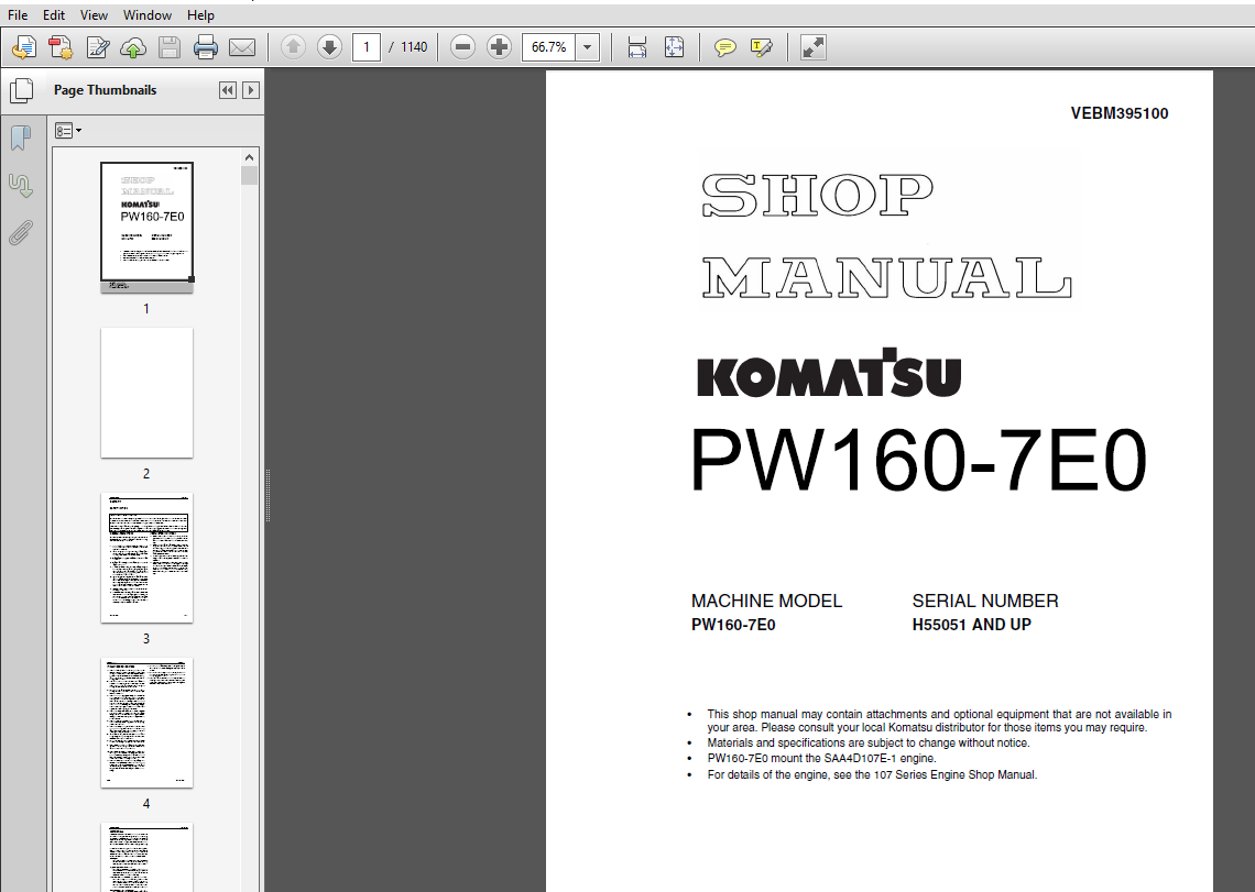
Product Code : VEBM395100
Total Pages : 1140
DESCRIPTION:
Komatsu PW160-7E0 Hydraulic Excavator Shop Manual (H55051 and up)
FOREWORD:
GENERAL:
This shop manual has been prepared as an aid to improve the quality of repairs by giving the serviceman an accurate understanding of the product and by showing him the correct way to perform repairs and make judgements. Make sure you understand the contents of this manual and use it to full effect at every opportunity. This shop manual mainly contains the necessary technical information for operations performed in a service workshop. For ease of understanding, the manual is divided into the following chapters: these chapters are further divided into the each main group of components.
STRUCTURE AND FUNCTION:
This section explains the structure and function of each component. It serves not only to give an understanding of the structure, but also serves as reference material for troubleshooting.
TESTING AND ADJUSTING:
This section explains checks to be made before and after performing repairs , as well as adjustments to be made at completion of the checks and repairs. Troubleshooting charts correlating “problems” to “Causes” are also included in this section.
DISASSEMBLY AND ASSEMBLY:
This section explains the order to be followed when removing, installing, disassembling or assembling eachr component, as well as precautions to be taken for these operations.
MAINTENANCE STANDARD:
This section gives the judgement standards when inspecting disassembled parts.
TABLE OF CONTENTS:
Komatsu PW160-7E0 Hydraulic Excavator Shop Manual (H55051 and up)
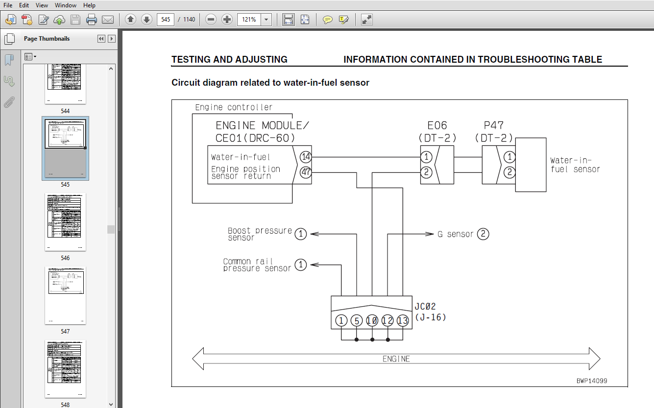
VEBM395100 PW160-7E0...........................................................................................................................   1
SAFETY.........................................................................................................................................   3
	SAFETY NOTICE..............................................................................................................................   3
		IMPORTANT SAFETY NOTICE................................................................................................................   3
		GENERAL PRECAUTIONS....................................................................................................................   3
		PRECAUTIONS DURING WORK................................................................................................................   4
01 GENERAL.....................................................................................................................................  21
	SPECIFICATION DIMENSION DRAWINGS...........................................................................................................  22
		DIMENSIONS.............................................................................................................................  22
			1 pIECE BOOM.......................................................................................................................  22
	WORKING RANGES.............................................................................................................................  24
		1 PIECE BOOM...........................................................................................................................  24
		2 PIECE BOOM...........................................................................................................................  25
	SPECIFICATIONS.............................................................................................................................  26
	WEIGHT TABLE...............................................................................................................................  28
		1 piece boom...........................................................................................................................  29
		2 piece boom...........................................................................................................................  30
	FUEL, COOLANT AND LUBRICANTS...............................................................................................................  31
10 STRUCTURE, FUNCTION AND.....................................................................................................................  33
	ENGINE RELATED PARTS.......................................................................................................................  34
	RADIATOR . OIL COOLER . CHARGE AIR COOLER..................................................................................................  35
	POWER TRAIN................................................................................................................................  36
	SWING CIRCLE...............................................................................................................................  38
	SWING MACHINERY & MOTOR....................................................................................................................  40
	SWING MOTOR................................................................................................................................  44
		Operation of swing lock................................................................................................................  48
		RELIEF VALVE PORTION...................................................................................................................  49
		Operation..............................................................................................................................  49
	UNDERCARRIAGE..............................................................................................................................  50
	TRANSMISSION...............................................................................................................................  52
	ATT EPC VALVE ASSEMBLY.....................................................................................................................  55
	QUICK COUPLER CONTROL VALVE................................................................................................................  56
	TRAVEL MOTOR...............................................................................................................................  58
		OPERATION OF TRAVEL MOTOR..............................................................................................................  60
	CLUTCH CONTROL CIRCUIT.....................................................................................................................  62
	AXLE.......................................................................................................................................  64
	SUSPENSION LOCK CYLINDER...................................................................................................................  68
	BRAKING SYSTEM.............................................................................................................................  70
	BRAKE/STEER PUMP...........................................................................................................................  72
	PRIORITY VALVE.............................................................................................................................  73
	POWER BRAKE VALVE..........................................................................................................................  74
		SPECIFICATIONS.........................................................................................................................  74
		FUNCTION...............................................................................................................................  75
	ACCUMULATOR for brake system...............................................................................................................  76
	STEERING SYSTEM............................................................................................................................  78
	STEERING COLUMN............................................................................................................................  79
	ORBITROL VALVE.............................................................................................................................  80
	HYDRAULIC EQUIPMENT LAYOUT DRAWINGS........................................................................................................  81
	HYDRAULIC CIRCUIT DIAGRAM..................................................................................................................  84
	HYDRAULIC TANK.............................................................................................................................  85
	HYDRAULIC PUMP.............................................................................................................................  86
		HPV125.................................................................................................................................  86
		LS VALVE...............................................................................................................................  91
		PC VALVE...............................................................................................................................  91
		LS(pc)-EPC VALVE....................................................................................................................... 104
	PILOT PRESSURE CONTROL (PPC) SYSTEM........................................................................................................ 107
	CONTROL VALVE.............................................................................................................................. 108
		PW160-7E0.............................................................................................................................. 108
	CLSS....................................................................................................................................... 118
		OUTLINE OF CLSS........................................................................................................................ 118
	CENTre SWIVEL JOINT........................................................................................................................ 139
	TRAVEL PPC PEDAL........................................................................................................................... 140
	WORK EQUIPMENT . SWING PPC VALVE........................................................................................................... 142
	SOLENOID VALVE MANIFOLD.................................................................................................................... 146
		SOLENOID VALVE BLOCK................................................................................................................... 147
			2 Position 3 way valve............................................................................................................. 147
			2 Position 4 way valve............................................................................................................. 149
		attachment epc valve................................................................................................................... 151
	BOOM SAFETY VALVE.......................................................................................................................... 154
	HYDRAULIC CYLINDER......................................................................................................................... 157
		BOOM CYLINDER.......................................................................................................................... 157
		ARM CYLINDER........................................................................................................................... 157
		BUCKET CYLINDER........................................................................................................................ 157
		ADJUST CYLINDER........................................................................................................................ 158
	OUTRIGGER CYLINDER......................................................................................................................... 160
	DOZER CYLINDER............................................................................................................................. 162
	WORK EQUIPMENT............................................................................................................................. 164
		Work Equipment......................................................................................................................... 165
		1. DIMENSION OF ARM.................................................................................................................... 167
		2. Dimension of bucket................................................................................................................. 168
	AIR CONDITIONER............................................................................................................................ 169
		air conditioner piping................................................................................................................. 169
	ELECTRICAL WIRING DIAGRAM.................................................................................................................. 170
	ELECTRICAL SYSTEM.......................................................................................................................... 171
		Engine Control......................................................................................................................... 171
		Engine controller...................................................................................................................... 173
		CN-CE01 (*: Never connect to NC as malfunctions and errors occur)...................................................................... 174
		CN-CE01 (*: Never connect to NC as malfunctions and errors occur)...................................................................... 174
		CN-CE02 (*: Never connect to NC as malfunctions and errors occur)...................................................................... 175
		CN-CE03(*: Never connect to NC as malfunctions and errors occur)....................................................................... 175
		Engine throttle and pump controller.................................................................................................... 175
	ELECTRONIC CONTROL SYSTEM.................................................................................................................. 178
		machine control system diagram......................................................................................................... 179
	MACHINE MONITOR SYSTEM..................................................................................................................... 202
		MONITOR PANEL.......................................................................................................................... 204
		LIQUID CRYSTAL MONITOR ADJUSTMENT SWITCH............................................................................................... 223
	OVERLOAD WARNING DEVICE.................................................................................................................... 230
		OUTLINE................................................................................................................................ 230
	SENSOR..................................................................................................................................... 231
	1st ATTACHMENT CIRCUIT HYDRAULIC PERFORMANCE (MAIN......................................................................................... 240
	TRAVEL SYSTEM.............................................................................................................................. 242
		TRAVEL CIRCUIT......................................................................................................................... 242
		oPERATIONAL AND CONTROL FEATURES....................................................................................................... 243
		Operator’s Input via travel mode switch................................................................................................ 243
		OVERRUN PROTECTION. This is dealt with through the action of the counterbalance spool in the motor control block.When the machin....... 243
	STEERING SYSTEM............................................................................................................................ 264
		Operating principles................................................................................................................... 264
		Dynamic Steering....................................................................................................................... 264
		2 - stage principle.................................................................................................................... 264
	SERVICE BRAKE AND SUSPENSION SYSTEM........................................................................................................ 277
		bRAKING SYSTEM......................................................................................................................... 277
		operation.............................................................................................................................. 280
		KOMTRAX terminal system................................................................................................................ 282
			KOMTRAX terminal................................................................................................................... 283
20 TESTING AND ADJUSTING....................................................................................................................... 285
	STANDARD VALUE TABLE FOR ENGINE RELATED PARTS.............................................................................................. 286
	STANDARD VALUE TABLE FOR CHASSIS RELATED PARTS............................................................................................. 287
		Flow control characteristic of PC valve (STD).......................................................................................... 298
	TESTING AND ADJUSTING...................................................................................................................... 299
		Measuring engine speed................................................................................................................. 300
		Measuring intake air pressure (boost pressure)......................................................................................... 302
		MEASUREMENT OF EXHAUST GAS COLOUR...................................................................................................... 303
		Adjusting valve clearance.............................................................................................................. 305
		Measuring compression pressure......................................................................................................... 307
		MEASUREMENT OF BLOW-BY PRESSURE........................................................................................................ 309
		Measuring engine oil pressure.......................................................................................................... 310
		CHECKING AND ADJUSTING AIR CONDITIONER COMPRESSOR BELT TENSION......................................................................... 311
		Replacing the fan belt................................................................................................................. 312
		Handling fuel system parts............................................................................................................. 313
		Releasing residual pressure from fuel system........................................................................................... 314
		Measuring fuel pressure................................................................................................................ 315
		Measuring fuel discharge, return and leakage........................................................................................... 317
		Bleeding air from fuel circuit......................................................................................................... 321
		Checking fuel circuit for leakage...................................................................................................... 322
		MEASUREMENT OF CLEARANCE IN SWING CIRCLE BEARINGS...................................................................................... 323
		INSPECTION AND ADJUSTMENT OF HYDRAULIC OIL PRESSURE IN HYDRAULIC CIRCUIT FOR WORK EQUIPMENT, SWING AND TRAVEL.......................... 324
		INSPECTION AND ADJUSTMENT OF CONTROL CIRCUIT OIL PRESSURE.............................................................................. 327
		Procedure for pressure reducing adjustment............................................................................................. 328
		INSPECTION AND ADJUSTMENT OF PUMP PC (Valve INLET) CONTROL OIL PRESSURE................................................................ 329
		INSPECTION AND ADJUSTMENT OF PUMP LS valve CONTROL OIL PRESSURE........................................................................ 332
		MEASUREMENT OF SOLENOID VALVE OUTPUT PRESSURE.......................................................................................... 336
			6 - Stage solenoid block........................................................................................................... 338
			4 - Stage solenoid block........................................................................................................... 340
			2 - Stage solenoid block........................................................................................................... 341
		MEASUREMENT OF PPC VALVE OUTPUT PRESSURE............................................................................................... 342
		ADJUSTMENT OF WORK EQUIPMENT AND SWING PPC VALVE....................................................................................... 344
		Measuring and adjusting quick coupler control valve output pressure.................................................................... 345
		testing travel motor relief pressure................................................................................................... 346
		adjusting travel motor relief pressure................................................................................................. 347
		Testing propshaft speed................................................................................................................ 348
		TESTING TRANSMISSION CLUTCH CONTROL CIRCUIT............................................................................................ 349
		INSPECTION OF LOCATIONS OF HYDRAULIC DRIFT OF WORK EQUIPMENT........................................................................... 351
			RELEASE OF REMAINING PRESSURE IN HYDRAULIC CIRCUIT................................................................................. 353
		MEASUREMENT OF OIL LEAKAGE AMOUNT...................................................................................................... 354
		AIR BLEEDING OF VARIOUS PARTS.......................................................................................................... 356
		INSPECTION PROCEDURES FOR DIODE........................................................................................................ 358
		SPECIAL FUNCTION OF MONITOR PANEL...................................................................................................... 359
			OPERATION OF OPERATORS MENU AND DISPLAY (OUTLINE).................................................................................. 361
			TABLE FOR FAILURE CODE NO.......................................................................................................... 368
			OPERATION AND DISPLAY OF SERVICE MENU.............................................................................................. 371
				Way of switching to Service Menu............................................................................................... 371
			Table for Monitoring Items......................................................................................................... 374
			Procedure for turning on KOMTRAX terminal.......................................................................................... 391
			KOMTRAX terminal lamp indications.................................................................................................. 394
			Preparation work for troubleshooting of electrical system.......................................................................... 397
		PM - Tune up service................................................................................................................... 399
	TROUBLESHOOTING............................................................................................................................ 403
		POINTS TO REMEMBER WHEN TROUBLESHOOTING................................................................................................ 404
		SEQUENCE OF EVENTS IN TROUBLESHOOTING.................................................................................................. 405
		POINTS TO REMEMBER WHEN CARRYING OUT MAINTENANCE....................................................................................... 406
		CHECKS BEFORE TROUBLESHOOTING.......................................................................................................... 414
		CLASSIFICATION AND STEPS FOR TROUBLESHOOTING........................................................................................... 415
			Failure-looking Phenomenon and Troubleshooting No.................................................................................. 416
			How to read electric wire code..................................................................................................... 419
		CONNECTOR LOCATION CHART AND ELECTRICAL CIRCUIT DIAGRAM BY SYSTEM...................................................................... 422
			CONNECTOR LOCATIONS................................................................................................................ 430
		CONNECTION TABLE FOR CONNECTOR PIN NUMBERS............................................................................................. 451
	TROUBLESHOOTING WHEN FAILURE CODE IS INDICATED............................................................................................. 485
		Before carrying out troubleshooting when failure code is displayed..................................................................... 487
		INFORMATION CONTAINED IN TROUBLESHOOTING TABLE......................................................................................... 488
			Relative Electrical Circuit Diagram................................................................................................ 489
			Failure code [CA111] EMC Critical Internal Failure................................................................................. 490
			Failure code [CA115] Engine Neutral and Backup Speed Sensor Error.................................................................. 491
			Failure code [CA122] Chg Air Press Sensor High Error............................................................................... 492
			Failure code [CA123] Chg Air Press Sensor Low Error................................................................................ 494
			Failure code [CA131] Throttle Sensor High Error.................................................................................... 496
			Failure code [CA132] Throttle Sensor Low Error..................................................................................... 498
			Failure code [CA144] Coolant Temp Sens High Error.................................................................................. 500
			Failure code [CA145] Coolant Temp Sens Low Error................................................................................... 502
			Failure code [CA153] Chg Air Temp Sensor High Error................................................................................ 504
			Failure code [CA154] Chg Air Temp Sensor Low Error................................................................................. 506
			Failure code [CA155] Chg Air Temp High Speed Derate................................................................................ 508
			Failure code [CA187] Sens Supply 2 Volt Low Error.................................................................................. 510
			Failure code [CA221] Ambient Press Sens High Error................................................................................. 512
			Failure code [CA222] Ambient Press Sens Low Error.................................................................................. 514
			Failure code [CA227] Sens Supply 2 Volt High Error................................................................................. 516
			Failure code [CA238] Ne Speed Sens Supply Volt Error............................................................................... 518
			Failure code [CA271] IMV/PCV1 Short Error.......................................................................................... 520
			Failure code [CA272] IMV/PCV1 Open Error........................................................................................... 522
			Failure code [CA322] Inj #1 (L#1) Open/Short Error................................................................................. 524
			Failure code [CA324] Inj #3 (L#3) Open/Short Error................................................................................. 527
			Failure code [CA331] Inj #2 (L#2) Open/Short Error................................................................................. 530
			Failure code [CA332] Inj #4 (L#4) Open/Short Error................................................................................. 533
			Failure code [CA342] Calibration Code Incompatibility.............................................................................. 536
			Failure code [CA351] Injectors Drive Circuit Error................................................................................. 537
			Failure code [CA352] Sensor Supply 1 Volt Low Error................................................................................ 540
			Failure code [CA386] Sens Supply 1 Volt High Error................................................................................. 542
			Failure code [CA428] Water in Fuel Sensor High Error............................................................................... 544
			Failure code [CA429] Water in Fuel Sensor Low Error................................................................................ 546
			Failure code [CA435] Eng Oil Press Sw Error........................................................................................ 548
			Failure code [CA441] Battery Voltage Low Error..................................................................................... 550
			Failure code [CA442] Battery Voltage High Error.................................................................................... 553
			Failure code [CA449] Rail Press Very High Error.................................................................................... 555
			Failure code [CA451] Rail Press Sensor High Error.................................................................................. 556
			Failure code [CA452] Rail Press Sensor Low Error................................................................................... 558
			Failure code [CA488] Chg Air Temp High Torque Derate............................................................................... 560
			Failure code [CA553] Rail Press High Error......................................................................................... 561
			Failure code [CA559] Rail Press Low Error.......................................................................................... 562
			Failure code [CA689] Eng Ne Speed Sensor Error..................................................................................... 564
			Failure code [CA731] Eng Bkup Speed Sens Phase Error............................................................................... 567
			Failure code [CA757] All Continuous Data Lost Error................................................................................ 568
			Failure code [CA778] Eng G Speed Sensor Error...................................................................................... 570
			Failure code [CA1633] KOMNET Datalink Timeout Error................................................................................ 574
			Failure code [CA2185] Throttle Sensor Supply Voltage High Error.................................................................... 576
			Failure code [CA2186] Throttle Sensor Supply Voltage Low Error..................................................................... 578
			Failure code [CA2249] Rail Press Very Low Error.................................................................................... 580
			Failure code [CA2311] IMV Solenoid Error........................................................................................... 582
			Failure code [CA2555] Grid Htr Relay Volt High Error............................................................................... 584
			Failure code [CA2556] Grid Heater Relay Volt Low Error............................................................................. 586
			Failure Code [D110KB] (Short-circuiting in battery relay).......................................................................... 588
			Failure code [D862KA] GPS Antenna Disconnection.................................................................................... 590
				Configuration diagram of KOMTRAX system........................................................................................ 590
			Failure Code [DA22KK] (Abnormality in pump pressure sensor)........................................................................ 592
			Failure code [DA25KP] Press. Sensor Power Abnormality.............................................................................. 594
			Failure code [DA2RMC] Pump Comm. Abnormality....................................................................................... 596
			Failure Code [DA2SKQ] (Abnormality in inputting model code)........................................................................ 598
			Failure Code [DA2SKQ] (Abnormality in inputting model code)........................................................................ 600
			Failure code [DAFRMC] Monitor Comm. Abnormality.................................................................................... 602
			Failure code [DDC3KZ] Outrigger Switch Select Abnormality.......................................................................... 604
			Failure Code [DDP4KX] (Abnormality in travel PPC pressure switch).................................................................. 606
			Failure Code [DDWCKZ] (Abnormality in travel direction control switch)............................................................. 608
			Failure code [DFB1KZ] Service Lever Potentio 1 Abnormality......................................................................... 610
			Failure code [DFB2KZ] Service Lever Potentio 2 Abnormality......................................................................... 613
			Failure code [DFB3L8] Service Lever 1 Potentio Error............................................................................... 616
			Failure code [DFB4L8] Service Lever 2 Potentio Error............................................................................... 617
			Failure code [DGH2KB] Hydr Oil Sensor Short........................................................................................ 619
			Failure Code [DH1OKS] (Abnormality in Pressure sensor power source)................................................................ 620
			Failure code [DHPAMA] F Pump Press Sensor Abnormality.............................................................................. 622
			Failure Code [DHS5KX] (Abnormality in travel PPC sensor)........................................................................... 624
			Failure Code [DHX1MA] (Abnormality in overload caution sensor)..................................................................... 626
			Failure Code [DLT4KA] (Disconnection in transmission speed sensor in pump controller system)....................................... 628
			Failure Code [DW27KA] (Disconnection in Transmission Clutch solenoid).............................................................. 630
			Failure Code [DW27KB] (Short-circuiting in Transmission Clutch solenoid)........................................................... 632
			Failure Code DW4AKA (Disconnection in suspension lock solenoid).................................................................... 634
			Failure Code [DW4AKB] (Short circuiting in suspension lock solenoid)............................................................... 636
			Failure Code [DW4CKA] (Disconnection in PPC lock solenoid)......................................................................... 638
			Failure code [DW4CKB] PPC Lock Sol. S/C............................................................................................ 640
			Failure Code [DW4MKA] (Disconnection in Creep solenoid)............................................................................ 642
			Failure Code [DW4MKB] (Short-circuiting in Creep solenoid)......................................................................... 644
			Failure Code [DW44KA] (Disconnection of Travel F/R solenoid)....................................................................... 646
			Failure Code [DW44KB] (Short-circuiting of Travel F/R solenoid).................................................................... 648
			Failure Code [DW45KA] (Disconnection in Swing Parking Brake solenoid).............................................................. 650
			Failure code [DW45KB] Swing Brake Sol. S/C......................................................................................... 654
			Failure Code [DW91KA] (Disconnection in Travel Neutral solenoid)................................................................... 656
			Failure Code [DW91KB] (Short-circuiting in Travel Neutral Solenoid)................................................................ 658
			Failure Code [DWK0KA] (Disconnection in 2-stage Relief solenoid)................................................................... 660
			Failure Code [DWK0KB] (Short-circuiting in 2-Stage Relief Solenoid)................................................................ 662
			Failure Code [DWK2KA] (Disconnection in 2-stage Back Pressure solenoid)............................................................ 664
			Failure Code [DWK2KB] (Short circuiting in 2-stage back pressure solenoid)......................................................... 666
			Failure Code [DXA0KA] (Disconnection in PC-EPC solenoid system).................................................................... 668
			Failure Code [DXA0KB] (Short-circuiting in PC-EPC solenoid)........................................................................ 670
			Failure Code [DXE0KA] (Disconnection in LS-EPC solenoid system).................................................................... 672
			Failure Code [DXE0KB] (Short-circuiting in LS-EPC solenoid)........................................................................ 674
			Failure code [DXE4KA] Service Current EPC1 Discon.................................................................................. 676
			Failure code [DXE4KB] Service Current EPC1 Short................................................................................... 678
			Failure code [DXE7KA] Service Current EPC2 Discon.................................................................................. 680
			Failure code [DXE7KB] Service Current EPC2 Short................................................................................... 682
			Failure code [DXE8KA] Service Current EPC3 Discon.................................................................................. 684
			Failure code [DXE8KB] Service Current EPC3 Short................................................................................... 686
			Failure code [DXE9KA] Service Current EPC4 Discon.................................................................................. 688
			Failure code [DXE9KB] Service Current EPC4 Short................................................................................... 690
			Failure code [DY20KA] Wiper Working Abnormality.................................................................................... 692
			Failure code [DY20MA] Wiper Parking Abnormality.................................................................................... 694
			Failure code [DY2CKB] Washer Drive S/C............................................................................................. 696
			Failure code [DY2DKB] Wiper Drive (For) S/C........................................................................................ 698
			Failure code [DY2EKB] Wiper Drive (Rev) S/C........................................................................................ 700
	TROUBLESHOOTING OF ELECTRICAL SYSTEM (E-MODE).............................................................................................. 703
		INFORMATION CONTAINED IN TROUBLESHOOTING TABLE......................................................................................... 704
			E-1 Engine does not start (Engine does not rotate)................................................................................. 706
			E-5 Auto-decelerator does not work................................................................................................. 711
			E-6 Auto engine warm-up device does not work....................................................................................... 713
			E-7 Preheater does not operate..................................................................................................... 714
			E-8 All work equipment, swing and travel do not move............................................................................... 716
			E-9 One-touch Power Max Switch does not work....................................................................................... 718
			E-10 No display in monitor panel at all............................................................................................ 719
			E-11 Part of display on monitor panel is missing................................................................................... 720
			E-12 Monitor panel displays contents irrelevant to the model....................................................................... 720
			E-13 Fuel level monitor red lamp lights up while engine is running................................................................. 721
			E-14 Engine coolant temperature gauge does not indicate normally................................................................... 722
			E-15 Hydraulic oil temperature gauge does not display correctly.................................................................... 724
			E-16 Fuel gauge does not display correctly......................................................................................... 725
			E-17 Swing lock monitor does not display correctly................................................................................. 726
			E-18 When the monitor switch is operated, no display appears....................................................................... 728
			E-19 Windshield wiper and window washer do not operate............................................................................. 729
			E-20 Alarm buzzer cannot be stopped................................................................................................ 731
			E-21 "Boom/Stabiliser RAISE" is not correctly displayed in monitor function........................................................ 732
			E-22 "Boom/Stabiliser LOWER" is not correctly displayed in monitor function........................................................ 733
			E-23 "Arm DIGGING" is not correctly displayed in monitor function.................................................................. 734
			E-24 "Arm DUMPING" is not correctly displayed in monitor function.................................................................. 735
			E-25 "Bucket DIGGING" is not correctly displayed in monitor function............................................................... 736
			E-26 "Bucket DUMPING" is not correctly displayed in monitor function............................................................... 737
			E-27 "SWING" is not correctly displayed in monitor function........................................................................ 738
			E-28 "TRAVEL" is not correctly displayed in monitor function....................................................................... 740
			E-29 "2 Piece Boom" is not correctly displayed in monitor function................................................................. 742
			E-30 Air Conditioner does not work................................................................................................. 744
			E-31 Travel reverse alarm does not sound........................................................................................... 746
			E-32 KOMTRAX system does not operate normally...................................................................................... 748
	TROUBLESHOOTING OF ELECTRICAL SYSTEM (Error checking of items without Monitor codes)....................................................... 751
		Relative Electrical Circuit Diagram.................................................................................................... 753
		Radio Cassette & Telephone Socket...................................................................................................... 754
			Electrical Circuit Diagram For Radio Cassette & Telephone Socket................................................................... 755
		PPC Lock Circuit....................................................................................................................... 756
			Circuit Diagram for PPC Lock Circuit............................................................................................... 757
		Brake Light Circuit.................................................................................................................... 758
			Circuit Diagram for Brake Light Circuit............................................................................................ 759
		Undercarriage Attachments - Mode Selection............................................................................................. 760
			Circuit Diagram for Undercarriage Attachments - Mode Selection..................................................................... 761
		Undercarriage Attachments - Front Left Outrigger....................................................................................... 762
			Circuit Diagram for Undercarriage Attachments - Front Left Outrigger............................................................... 763
		Undercarriage Attachments - Front Right Outrigger...................................................................................... 764
			Circuit Diagram for Undercarriage Attachments - Front Right Outrigger.............................................................. 765
		Undercarriage Attachments - Rear Left Outrigger........................................................................................ 766
		Undercarriage Attachments - Rear Right Outrigger....................................................................................... 768
			Circuit Diagram for Undercarriage Attachments - Rear Right Outrigger............................................................... 769
		Heated Seat Does Not Warm Up........................................................................................................... 770
			Circuit Diagram for the Heated Seat................................................................................................ 771
		Suspension Lock........................................................................................................................ 772
			Circuit Diagram for Suspension Lock................................................................................................ 773
		Lower Wiper Does Not Work (Optional Fitment)........................................................................................... 774
			Circuit Diagram for Lower Wiper.................................................................................................... 775
		Work Lights (Operator Cab Front Left).................................................................................................. 776
		Work Lights (Operator Cab Front Right)................................................................................................. 777
		Work Lights (Operator Cab Rear)........................................................................................................ 778
			Circuit Diagram for Work Lights.................................................................................................... 779
		Worklights (Boom, Arm & Counterweight)................................................................................................. 780
			Circuit Diagram for Worklights (Boom & Counterweight).............................................................................. 781
		Cab and Counterweight Beacon Light..................................................................................................... 782
			Circuit Diagram for Cab & Counterweight Beacon Light............................................................................... 783
		Air Seat Compressor (Option - Air Suspension Seat)..................................................................................... 784
			Circuit Diagram for Air Seat Compressor (Option - Air Suspension Seat)............................................................. 785
		Operator Cab Interior Light............................................................................................................ 786
			Circuit Diagram for Operator Cab Interior Light.................................................................................... 787
		Cigar Lighter.......................................................................................................................... 788
			Circuit Diagram for Cigar Lighter.................................................................................................. 789
		Park Brake (Not Activating)............................................................................................................ 790
			Circuit Diagram for Park Brake..................................................................................................... 791
		Park Brake (Displayed Symbol).......................................................................................................... 792
			Circuit Diagram for Park Brake..................................................................................................... 793
		RH PPC Lever Clamshell Roller Switch Pushed to the LH Position......................................................................... 794
			Circuit Diagram for Clamshell Control.............................................................................................. 795
		RH PPC Lever Clamshell Roller Switch Pushed to the RH Position......................................................................... 796
			Circuit Diagram for Clamshell Control.............................................................................................. 797
		RH PPC Lever Clamshell Roller Switched Pushed to the RH or LH.......................................................................... 798
			Circuit Diagram for Clamshell Control.............................................................................................. 799
		Horns.................................................................................................................................. 800
			Circuit Diagram for Horn........................................................................................................... 801
		Swing Lock - Normal Operation.......................................................................................................... 802
			Circuit Diagram for Swing Lock..................................................................................................... 803
		Swing Lock - Emergency Operation....................................................................................................... 804
			Circuit Diagram for Swing Lock - Emergency Operation............................................................................... 805
		Neutral Start (Engine)................................................................................................................. 806
		Neutral Start (Engine) cont’d (A)...................................................................................................... 807
		Neutral Start (Engine) cont’d (B)...................................................................................................... 808
		Neutral Start (Engine) cont’d (C)...................................................................................................... 809
			Circuit Diagram for Neutral Start (Engine)......................................................................................... 810
		Emergency Travel Control - Forward..................................................................................................... 811
			Circuit Diagram for Travel Direction Control....................................................................................... 812
		Emergency Travel Control - Neutral..................................................................................................... 813
			Circuit Diagram for Travel Direction Control....................................................................................... 814
		Emergency Travel Control - Reverse..................................................................................................... 815
		Emergency Travel Control - Reverse cont’d.............................................................................................. 816
			Circuit Diagram for Travel Direction Control....................................................................................... 817
		Driving Lights - Main Beam............................................................................................................. 818
			Circuit Diagram for Driving Lights................................................................................................. 819
		Driving Lights - Main Beam Flash....................................................................................................... 820
			Circuit Diagram for Driving Lights................................................................................................. 821
		Driving Lights - Main Beam Dipped...................................................................................................... 822
			Circuit Diagram for Driving Lights................................................................................................. 823
		Driving Lights - Position Lights....................................................................................................... 824
			Circuit Diagram for Driving Lights................................................................................................. 825
		Driving Lights - Position Lights cont’d (1) and (2).................................................................................... 826
			Circuit Diagram for Driving Lights................................................................................................. 827
		Indicators - Right Hand................................................................................................................ 828
			Circuit Diagram for Indicators & Hazard Warning.................................................................................... 829
		Indicators - Left Hand................................................................................................................. 830
			Circuit Diagram for Indicators & Hazard Warning.................................................................................... 831
		Hazard Warning Lights.................................................................................................................. 832
			Circuit Diagram for Indicators & Hazard Warning.................................................................................... 833
		Hazard Warning Lights cont’d (A)....................................................................................................... 834
			Circuit Diagram for Indicators & Hazard Warning.................................................................................... 835
		Swing Lock Proximity Switch............................................................................................................ 836
			Brake and Swing Lock Proximity Switches............................................................................................ 837
	TROUBLESHOOTING OF HYDRAULIC AND MECHANICAL SYSTEM (H-MODE)................................................................................ 839
		SYSTEM CHART FOR HYDRAULIC AND MECHANICAL SYSTEMS...................................................................................... 840
		INFORMATION CONTAINED IN TROUBLESHOOTING TABLE......................................................................................... 844
		Quick coupler.......................................................................................................................... 863
30 DISASSEMBLY AND ASSEMBLY.................................................................................................................... 865
	HOW TO READ THIS MANUAL.................................................................................................................... 869
		REMOVAL AND INSTALLATION OF ASSEMBLIES................................................................................................. 869
		DisassemblY and assemblY OF assemblIES................................................................................................. 870
	SPECIAL TOOLS.............................................................................................................................. 875
		SKETCHES............................................................................................................................... 875
		LIST OF TOOLS.......................................................................................................................... 876
	PRECAUTIONS WHEN PERFORMING OPERATION...................................................................................................... 880
	STARTING MOTOR ASSEMBLY.................................................................................................................... 882
	FUEL Supply PUMP assembly.................................................................................................................. 883
	FUEL INJECTOR ASSEMBLY..................................................................................................................... 886
	FRONT OIL SEAL............................................................................................................................. 891
	REAR OIL SEAL.............................................................................................................................. 893
	CYLINDER HEAD ASSEMBLY..................................................................................................................... 896
	COMBINATION COOLER......................................................................................................................... 906
	FUEL COOLER ASSEMBLY....................................................................................................................... 909
	ENGINE AND HYDRAULIC PUMP ASSEMBLIES....................................................................................................... 910
	TRAVEL MOTOR ASSEMBLY...................................................................................................................... 917
	TRAVEL MOTOR ASSEMBLY...................................................................................................................... 919
	SWING MOTOR AND SWING MACHINERY ASSEMBLY................................................................................................... 923
	SWING MACHINERY ASSEMBLY................................................................................................................... 924
	SWING MOTOR ASSEMBLY....................................................................................................................... 932
	FRONT AXLE ASSEMBLY........................................................................................................................ 941
	FRONT AXLE ASSEMBLY........................................................................................................................ 943
	REAR AXLE AND TRANSMISSION ASSEMBLY........................................................................................................ 992
	REAR AXLE ASSEMBLY......................................................................................................................... 995
	TRANSMISSION ASSEMBLY......................................................................................................................1025
	PROPSHAFT ASSEMBLY.........................................................................................................................1054
	WHEEL ASSEMBLY.............................................................................................................................1056
	SUSPENSION LOCK CYLINDER ASSEMBLY..........................................................................................................1057
	SUSPENSION LOCK CYLINDERS ASSEMBLY.........................................................................................................1058
	OUTRIGGER ASSEMBLY.........................................................................................................................1059
	OUTRIGGER ASSEMBLY.........................................................................................................................1060
	DOZER BLADE................................................................................................................................1061
	DOZER BLADE ASSEMBLY.......................................................................................................................1062
	SWING CIRCLE ASSEMBLY......................................................................................................................1063
	REVOLVING FRAME ASSEMBLY...................................................................................................................1064
	CENTRE SWIVEL JOINT ASSEMBLY...............................................................................................................1067
	CENTRE SWIVEL JOINT ASSEMBLY...............................................................................................................1070
	HYDRAULIC TANK ASSEMBLY....................................................................................................................1072
	FUEL TANK ASSEMBLY.........................................................................................................................1076
	CONTROL VALVE ASSEMBLY.....................................................................................................................1078
	LS SEPARATION VALVE ASSEMBLY...............................................................................................................1082
	PRESSURE COMPENSATION VALVE ASSEMBLY.......................................................................................................1083
	MAIN RELIEF VALVE ASSEMBLY.................................................................................................................1084
	LS CONTROL EPC VALVE ASSEMBLY..............................................................................................................1085
	EPC SOLENOID VALVE ASSEMBLY................................................................................................................1086
	4 STATION PPC SOLENOID VALVE BLOCK ASSEMBLY................................................................................................1087
	MANIFOLD BLOCK ASSEMBLY....................................................................................................................1089
	OIL SEAL IN HYDRAULIC PUMP INPUT SHAFT.....................................................................................................1090
	WORK EQUIPMENT PPC VALVE ASSEMBLY..........................................................................................................1091
	HYDRAULIC CYLINDER ASSEMBLY................................................................................................................1092
	MONOBOOM WORK EQUIPMENT ASSEMBLY...........................................................................................................1098
	2 PIECE BOOM WORK EQUIPMENT ASSEMBLY.......................................................................................................1101
	AIR CONDITIONER UNIT ASSEMBLY..............................................................................................................1104
	COUNTERWEIGHT ASSEMBLY.....................................................................................................................1108
	OPERATOR CAB ASSEMBLY......................................................................................................................1110
	MONITOR ASSEMBLY...........................................................................................................................1113
	GOVERNOR / PUMP CONTROLLER ASSEMBLY........................................................................................................1114
	KOMTRAX TERMINAL...........................................................................................................................1115
	ENGINE CONTROLLER..........................................................................................................................1116
90 OTHERS......................................................................................................................................1117
	Mono boom..................................................................................................................................1118
	Two plece boom.............................................................................................................................1119
	Hydraulic circuit diagram 1/3..............................................................................................................1121
	Hydraulic circuit diagram 2/3..............................................................................................................1123
	Hydraulic circuit diagram 3/3..............................................................................................................1125
	Electrical circuit diagram 1/7.............................................................................................................1127
	Electrical circuit diagram 2/7.............................................................................................................1129
	Electrical circuit diagram 3/7.............................................................................................................1131
	Electrical circuit diagram 4/7.............................................................................................................1133
	Electrical circuit diagram 5/7.............................................................................................................1135
	Electrical circuit diagram 6/7.............................................................................................................1137
	Electrical circuit diagram 7/7.............................................................................................................1139
IMAGES PREVIEW OF THE MANUAL:

PLEASE NOTE:
- This is the SAME MANUAL used by the dealerships to diagnose your vehicle
- No waiting for couriers / posts as this is a PDF manual and you can download it within 2 minutes time once you make the payment.
- Your payment is all safe and the delivery of the manual is INSTANT – You will be taken to the DOWNLOAD PAGE.
- So have no hesitations whatsoever and write to us about any queries you may have : heydownloadss @gmail.com
More products