$45
Komatsu PW160-7K Hydraulic Excavator Shop Manual (K40001 and up) - PDF DOWNLOAD
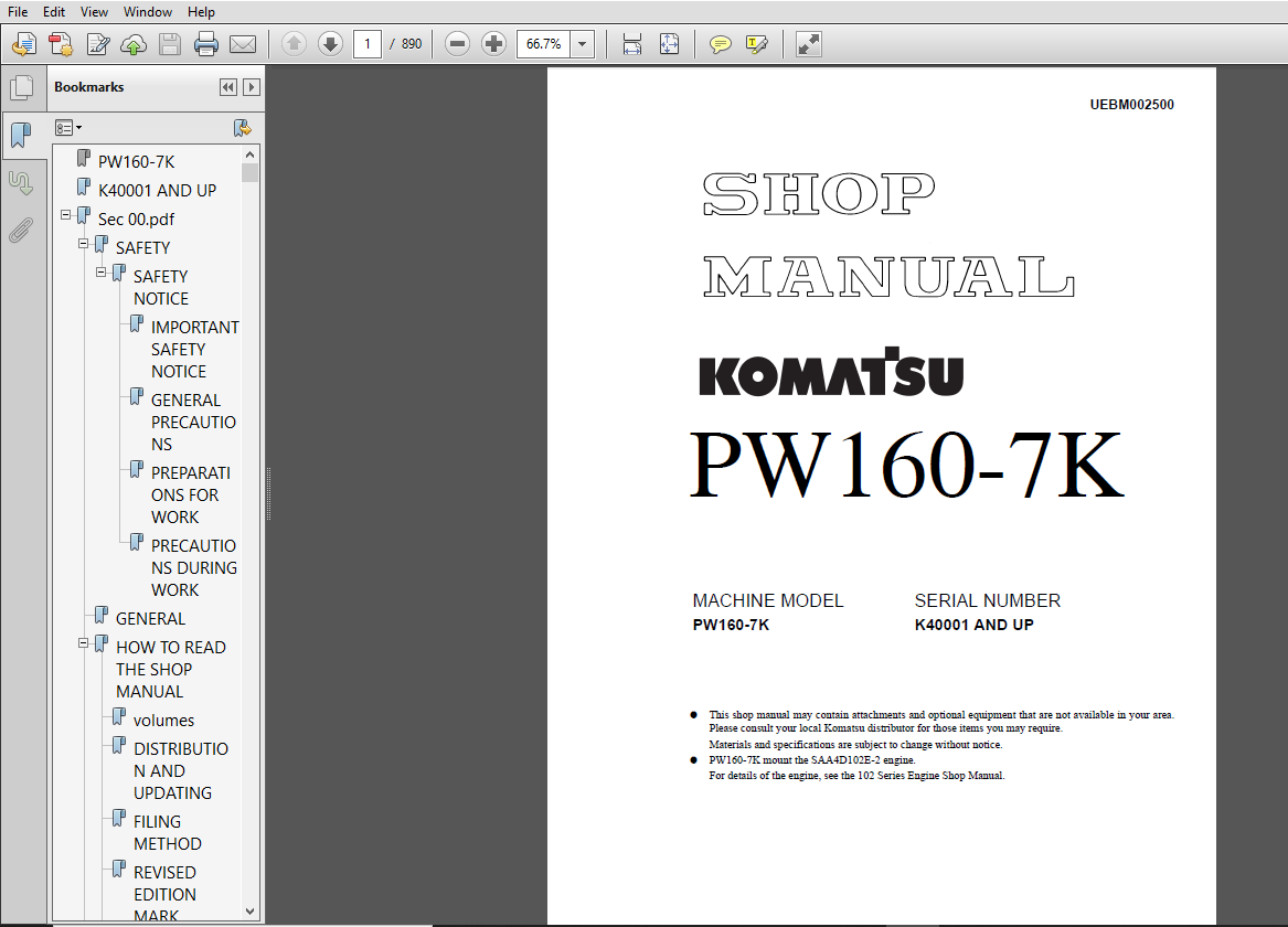
Komatsu PW160-7K Hydraulic Excavator Shop Manual (K40001 and up)
FILE DETAILS:
Komatsu PW160-7K Hydraulic Excavator Shop Manual (K40001 and up)
File Format : PDF
Language : English
Printable : Yes
Searchable : Yes
Product Code : UEBM002500
Total Pages : 890
DESCRIPTION:
Komatsu PW160-7K Hydraulic Excavator Shop Manual (K40001 and up)
FOREWORD:
GENERAL:
This shop manual has been prepared as an aid to improve the quality of repairs by giving the serviceman an accurate understanding of the product and by showing him the correct way to perform repairs and make judgements. Make sure you understand the contents of this manual and use it to full effect at every opportunity. This shop manual mainly contains the necessary technical information for operations performed in a service workshop. For ease of understanding, the manual is divided into the following chapters: these chapters are further divided into the each main group of components.
STRUCTURE AND FUNCTION:
This section explains the structure and function of each component. It serves not only to give an understanding of the structure, but also serves as reference material for troubleshooting.
TESTING AND ADJUSTING:
This section explains checks to be made before and after performing repairs , as well as adjustments to be made at completion of the checks and repairs. Troubleshooting charts correlating “problems” to “Causes” are also included in this section.
DISASSEMBLY AND ASSEMBLY:
This section explains the order to be followed when removing, installing, disassembling or assembling eachr component, as well as precautions to be taken for these operations.
MAINTENANCE STANDARD:
This section gives the judgement standards when inspecting disassembled parts.
TABLE OF CONTENTS:
Komatsu PW160-7K Hydraulic Excavator Shop Manual (K40001 and up)
PW160-7K........................................................................................................ 1
K40001 AND UP................................................................................................... 1
Sec 00.pdf...................................................................................................... 0
SAFETY...................................................................................................... 3
SAFETY NOTICE........................................................................................... 3
IMPORTANT SAFETY NOTICE............................................................................. 3
GENERAL PRECAUTIONS................................................................................. 3
PREPARATIONS FOR WORK............................................................................... 3
PRECAUTIONS DURING WORK............................................................................. 4
GENERAL..................................................................................................... 5
HOW TO READ THE SHOP MANUAL................................................................................. 6
volumes................................................................................................. 6
DISTRIBUTION AND UPDATING............................................................................... 6
FILING METHOD........................................................................................... 6
REVISED EDITION MARK.................................................................................... 6
REVISIONS............................................................................................... 6
SYMBOLS................................................................................................. 6
HOISTING INSTRUCTIONS....................................................................................... 7
HOISTING................................................................................................ 7
WIRE ROPES.............................................................................................. 7
PUSH-PULL TYPE COUPLERS..................................................................................... 8
COATING MATERIALS........................................................................................... 10
STANDARD TIGHTENING TORQUE.................................................................................. 12
STANDARD TIGHTENING TORQUE OF BOLTS AND NUTS............................................................ 12
TIGHTENING TORQUE OF HOSE NUTS.......................................................................... 13
TIGHTENING TORQUE OF SPLIT FLANGE BOLTS................................................................. 13
TIGHTENING TORQUE FOR FLARED NUTS....................................................................... 13
Tightening torque for 102 engine series (bolts and nuts)................................................ 14
Tightening torque for 102 engine series (eye joints).................................................... 14
Tightening torque for 102 engine series (tapered screws)................................................ 14
ELECTRIC WIRE CODE.......................................................................................... 15
CLASSIFICATION BY THICKNESS............................................................................. 15
CLASSIFICATION BY COLOR AND CODE........................................................................ 15
CONVERSION TABLES........................................................................................... 16
METHOD OF USING THE CONVERSION TABLE.................................................................... 16
UNITS....................................................................................................... 22
01.pdf.......................................................................................................... 0
WORKING RANGES.............................................................................................. 26
1 PIECE BOOM............................................................................................ 26
2 PIECE BOOM............................................................................................ 27
SPECIFICATION DIMENSION DRAWINGS............................................................................ 24
DIMENSIONS.................................................................................................. 24
1 pIECE BOOM............................................................................................ 24
DIMENSIONS.................................................................................................. 25
2 PIECE BOOM............................................................................................ 25
SPECIFICATIONS.............................................................................................. 28
WEIGHT TABLE................................................................................................ 30
1 piece boom............................................................................................ 31
2 piece boom............................................................................................ 31
FUEL, COOLANT AND LUBRICANTS................................................................................ 32
10.pdf.......................................................................................................... 0
ENGINE RELATED PARTS........................................................................................ 34
RADIATOR • OIL COOLER • charge air cooler................................................................... 35
POWER TRAIN................................................................................................. 36
SWING CIRCLE................................................................................................ 38
SWING MACHINERY & motor..................................................................................... 40
SWING MOTOR................................................................................................. 44
Operation of swing lock................................................................................. 48
RELIEF VALVE PORTION.................................................................................... 49
Operation............................................................................................... 49
UNDERCARRIAGE............................................................................................... 50
TRANSMISSION................................................................................................ 52
TRAVEL MOTOR................................................................................................ 55
oPERATION OF TRAVEL MOTOR............................................................................... 57
CLUTCH CONTROL CIRCUIT...................................................................................... 59
AXLE........................................................................................................ 61
sUSPENSION LOCK CYLINDER.................................................................................... 65
Braking System.............................................................................................. 68
brake/steer pump............................................................................................ 70
PRIORITY VALVE.............................................................................................. 71
Power brake valve........................................................................................... 72
ACCUMULATOR for brake system................................................................................ 73
STEERING TRAIN.............................................................................................. 74
STEERING COLUMN............................................................................................. 75
ORBITROL VALVE.............................................................................................. 76
hydraulic equipment layout drawingS......................................................................... 78
hydraulic CIRCUIT dIAgRAM................................................................................... 80
HYDRAULIC TANK.............................................................................................. 81
HYDRAULIC PUMP.............................................................................................. 82
HPV125.................................................................................................. 82
LS VALVE................................................................................................ 87
PC VALVE................................................................................................ 87
LS(pc)-EPC VALVE........................................................................................100
PILOT PRESSURE CONTROL (PPC) SYSTEM.........................................................................103
CONTROL VALVE...............................................................................................104
PW160-7K................................................................................................104
CLSS........................................................................................................115
OUTLINE OF CLSS.........................................................................................115
CENTre SWIVEL JOINT.........................................................................................135
travel ppc pedal............................................................................................136
WORK EQUIPMENT • SWING PPC VALVE............................................................................138
SERVICE PPC VALVE...........................................................................................142
solenoid valve MANIFOLD.....................................................................................145
Solenoid valve (2, 4 & 6-stage solenoid)................................................................146
attachment epc valve....................................................................................147
Boom safety valve...........................................................................................150
HYDRAULIC CYLINDER..........................................................................................152
BOOM CYLINDER...........................................................................................152
ARM CYLINDER............................................................................................152
BUCKET CYLINDER.........................................................................................152
ADJUST CYLINDER.........................................................................................153
Outrigger CYLINDER..........................................................................................154
dozer CYLINDER..............................................................................................156
work equipment..............................................................................................158
Work Equipment..........................................................................................159
1. DIMENSION OF ARM.....................................................................................160
2. Dimension of bucket..................................................................................161
air conditioner.............................................................................................162
air conditioner piping..................................................................................162
electrical wiring diagram...................................................................................163
engine control system.......................................................................................164
Governor motor..........................................................................................166
Engine throttle and pump controller.....................................................................168
ELECTRONIC CONTROL SYSTEM...................................................................................170
machine control system diagram..........................................................................172
machine MONITOR SYSTEM......................................................................................195
Monitor panel...........................................................................................196
Overload warning device.....................................................................................215
OUTLINE.................................................................................................215
SENSOR......................................................................................................216
1st attachment circuit hydraulic performance (main valve bypassed)..........................................220
1st attachment circuit hydraulic performance (VIA main valve)...............................................222
travel system...............................................................................................224
TRAVEL CIRCUIT..........................................................................................224
oPERATIONAL AND CONTROL FEATURES........................................................................225
SteeRING system.............................................................................................246
Operating principles....................................................................................246
SERVICE BRAKE AND SUSPENSION SYSTEM.........................................................................259
bRAKING SYSTEM..........................................................................................259
operation...............................................................................................262
20_001.pdf...................................................................................................... 0
STANDARD VALUE TABLE FOR ENGINE RELATED PARTS...............................................................266
STANDARD VALUE TABLE FOR CHASSIS RELATED PARTS..............................................................267
Flow control characteristic of PC valve (STD)...........................................................278
20_101.pdf...................................................................................................... 0
INSPECTION AND ADJUSTMENT OF ENGINE RPM.....................................................................280
MEASUREMENT OF EXHAUST GAS COLOR............................................................................282
ADJUSTMENT OF VALVE CLEARANCE...............................................................................284
MEASUREMENT OF COMPRESSION PRESSURE.........................................................................286
MEASUREMENT OF BLOW-BY PRESSURE.............................................................................287
INSPECTION AND ADJUSTMENT OF FUEL INJECTION TIMING..........................................................288
MEASUREMENT OF ENGINE OIL PRESSURE..........................................................................291
EMERGENcy sEtting iF FAILURE occurs IN ENGINE CONTROL SYSTEM................................................294
MEASUREMENT OF CLEARANCE IN SWING CIRCLE BEARINGS...........................................................295
INSPECTION AND ADJUSTMENT OF HYDRAULIC OIL PRESSURE IN HYDRAULIC CIRCUIT FOR WORK EQUIPMENT, SWIN...........296
INSPECTION AND ADJUSTMENT OF CONTROL CIRCUIT OIL PRESSURE...................................................299
INSPECTION AND ADJUSTMENT OF PUMP PC (Valve INLET) CONTROL OIL PRESSURE.....................................301
INSPECTION AND ADJUSTMENT OF PUMP LS valve CONTROL OIL PRESSURE.............................................304
MEASUREMENT OF SOLENOID VALVE OUTPUT PRESSURE...............................................................308
7 - Stage solenoid block................................................................................310
4 - Stage solenoid block................................................................................312
2 - Stage solenoid block................................................................................313
MEASUREMENT OF PPC VALVE OUTPUT PRESSURE....................................................................314
ADJUSTMENT OF WORK EQUIPMENT AND SWING PPC VALVE............................................................316
testing travel motor relief pressure........................................................................317
adjusting travel motor relief pressure......................................................................318
Testing propshaft speed.....................................................................................319
tESTING TRANSMISSION CLUTCH CONTROL CIRCUIT.................................................................320
INSPECTION OF LOCATIONS OF HYDRAULIC DRIFT OF WORK EQUIPMENT................................................322
MEASUREMENT OF OIL LEAKAGE AMOUNT...........................................................................324
AIR BLEEDING OF VARIOUS PARTS...............................................................................326
INSPECTION PROCEDURES FOR DIODE.............................................................................328
SPECIAL FUNCTION OF MONITOR PANEL...........................................................................329
Operation of Operator's Menu and Display (Outline)......................................................331
Table for Service and Failure Code Nos..................................................................337
Operation and Display of Service Menu...................................................................340
Way of switching to Service Menu....................................................................340
PREPARATIONS FOR TROUBLESHOOTING ELECTRICAL SYSTEM..........................................................360
20_201.pdf...................................................................................................... 0
TROUBLESHOOTING.............................................................................................361
POINTS TO REMEMBER WHEN TROUBLESHOOTING.................................................................362
SEQUENCE OF EVENTS IN TROUBLESHOOTING...................................................................363
POINTS TO REMEMBER WHEN CARRYING OUT MAINTENANCE........................................................364
CHECKS BEFORE TROUBLESHOOTING...........................................................................372
CLASSIFICATION AND STEPS FOR TROUBLESHOOTING............................................................373
Classification of troubleshooting...................................................................373
Steps for troubleshooting...........................................................................373
Failure-looking Phenomenon and Troubleshooting No...................................................374
CONNECTOR LOCATION CHART AND ELECTRICAL CIRCUIT DIAGRAM BY SYSTEM.......................................378
CONNECTOR LOCATION STEREOGRAM.......................................................................384
CONNECTION TABLE FOR CONNECTOR PIN NUMBERS..............................................................392
20_301.pdf...................................................................................................... 0
TROUBLESHOOTING WHEN SERVICE CODE "ELECTRICAL SYSTEM" AND FAILURE CODE "MECHANICAL SYSTEM" ARE IN...........421
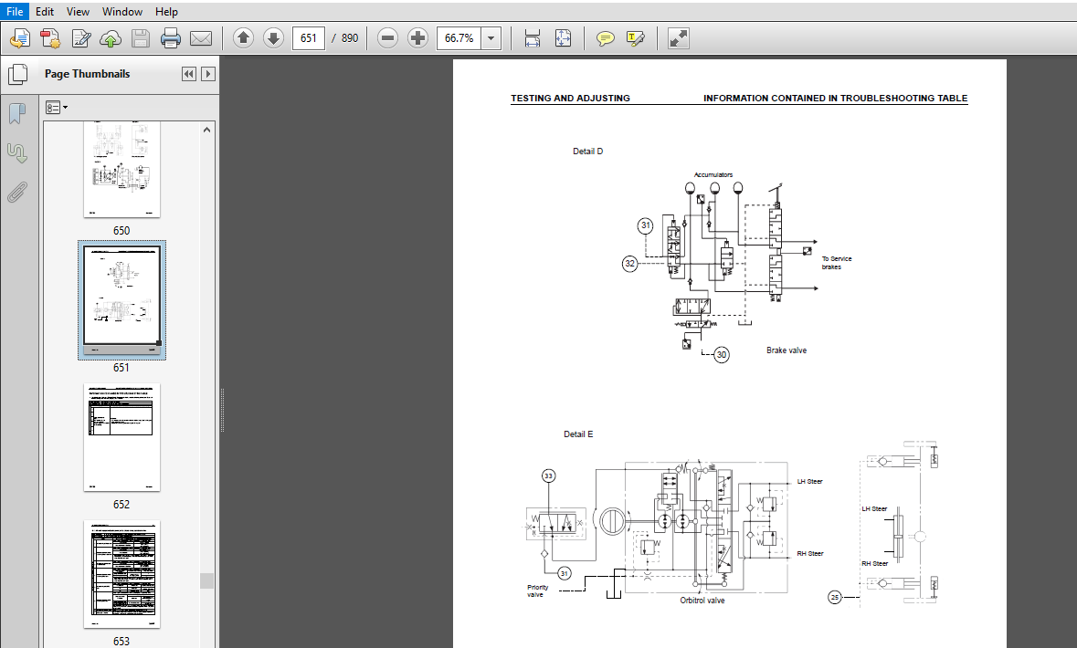
INFORMATION CONTAINED IN TROUBLESHOOTING TABLE..........................................................424
Service Code in Electrical System (Abnormal data in Error History)......................................426
Service Code in Electrical System (Disconnection of S-NET signal).......................................428
Service Code in Electrical System (Short-circuiting in Travel Neutral Solenoid).........................430
Service Code in Electrical System (Short-circuiting of Travel F/R solenoid).............................432
Service Code in Electrical System (Short-circuiting in 2-Stage Relief solenoid).........................434
Service Code in Electrical System (Short-circuiting in Transmission Clutch solenoid)....................436
Service Code in Electrical System (Short-circuiting in Creep solenoid)..................................438
Service Code in Electrical System (Disconnection in Creep solenoid).....................................440
Service Code in Electrical System (Disconnection in Travel Neutral solenoid)............................442
Service Code in Electrical System (Disconnection of Travel F/R solenoid)................................444
Service Code in Electrical System (Disconnection in Swing Parking Brake solenoid).......................446
Service Code in Electrical System (Disconnection in 2-stage Relief solenoid)............................448
Service Code in Electrical System (Disconnection in Transmission Clutch solenoid).......................450
Service Code in Electrical System (Abnormality in inputting model code).................................452
Service Code in Electrical System (Abnormality in inputting model code).................................454
Service Code in Electrical System Disconnection of S-NET signal)........................................456
Service Code in Electrical System (Short-circuiting in LS-EPC solenoid).................................458
Service Code in Electrical System (Disconnection in LS-EPC solenoid system).............................459
Service Code in Electrical System (Abnormality in pump pressure sensor).................................460
Service Code in Electrical System (Abnormality in Pressure sensor power source).........................462
Service Code in Electrical System (Abnormality in engine rotation sensor in governor • pump contr.......464
Service Code in Electrical System (Short-circuiting in PC-EPC solenoid).................................466
Service Code in Electrical System (Disconnection in PC-EPC solenoid system).............................468
Service Code in Electrical System (Short circuiting in 2-stage back pressure solenoid)..................470
Service Code in Electrical System (Disconnection in 2-stage Back Pressure solenoid).....................472
Service Code in Electrical System (Short-circuiting in attachment oil flow rate adjusting EPC)..........474
Service Code in Electrical System (Disconnection in attachment oil flow rate adjusting EPC).............475
Service Code in Electrical System (Abnormality in direction control switch).............................476
Service Code In Electrical System (Abnormality in overload caution sensor)..............................478
Service Code in Electrical System (Abnormality in travel PPC sensor)....................................480
Service Code in Electrical System (Disconnection in transmission speed sensor in governor • pump .......482
Service Code in Electrical System (Incorrect non-volatile memory data)..................................484
Service Code in Electrical System (Abnormality in travel PPC switch hydraulics).........................485
Service Code in Electrical System (Abnormality in governor potentiometer)...............................487
Service Code in Electrical System (Abnormality in fuel dial)............................................489
Service Code in Electrical System (Short-circuiting in battery relay)...................................491
Service Code in Electrical System (Step-out in governor motor)..........................................493
Service Code in Electrical System (Disconnection in governor motor Phase A and B).......................495
Service Code in Electrical System (Short-circuiting in governor motor Phase A and Phase B)..............497
Service Code in Electrical System ("Model Selection" function not provided yet).........................499
Service Mode in Electrical System (Model selecting signal fault)........................................500
Failure Code in Mechanical System (Out-of-rate engine rotation at high idling)..........................501
Failure Code in Mechanical System A000N2 (Out-of-rate engine rotation at low idling)....................501
Failure Code in Mechanical System (Air cleaner clogging)................................................502
Failure Code in Mechanical System (Abnormally lowered charging voltage).................................503
Failure Code in Mechanical System (Abnormally lowered engine oil pressure)..............................505
Failure Code in Mechanical System (Abnormally lowered engine oil level).................................506
Failure Code in Mechanical System (Engine cooling water overheating)....................................507
Failure Code in Mechanical System (Abnormally lowered radiator water level).............................508
Failure Code in Mechanical System (Hydraulic oil overheating)...........................................509
20_501.pdf...................................................................................................... 0
INFORMATION CONTAINED IN TROUBLESHOOTING TABLE..............................................................512
E-1 Engine does not start (Engine does not rotate)..........................................................513
E-2 Engine stops while in operation.........................................................................516
E-3 Engine speed is irregular, or there is hunting..........................................................518
E-4 Engine does not stop....................................................................................520
E-5 Auto-decelerator does not work..........................................................................522
E-6 Auto engine warm-up device does not work................................................................523
E-7 Pre heater does not work................................................................................524
E-8 All work equipment, swing and travel do not move........................................................526
E-9 One-touch Power Max Switch does not work................................................................528
E-10 No display in monitor panel at all.....................................................................529
E-11 Part of display on monitor panel is missing............................................................530
E-12 Monitor panel displays contents irrelevant to the model................................................530
E-13 Fuel level monitor red lamp lights up while engine is running..........................................531
E-14 Engine cooling water temperature gauge does not indicate correctly.....................................532
E-15 Hydraulic oil temperature gauge does not display correctly.............................................533
E-16 Fuel gauge does not display correctly..................................................................534
E-17 Swing lock monitor does not display correctly..........................................................536
E-18 When the monitor switch is operated, no display appears................................................538
E-19 Windshield wiper does not work.........................................................................540
E-21 "Boom/Stabiliser RAISE" is not correctly displayed in monitor function.................................542
E-22 "Boom LOWER" is not correctly displayed in monitor function............................................543
E-23 "Arm DIGGING" is not correctly displayed in monitor function...........................................544
E-24 "Arm DUMPING" is not correctly displayed in monitor function...........................................545
E-25 "Bucket DIGGING" is not correctly displayed in monitor function........................................546
E-26 "Bucket DUMPING" is not correctly displayed in monitor function........................................547
E-27 "SWING" is not correctly displayed in monitor function.................................................548
E-28 "TRAVEL" is not correctly displayed in monitor function................................................550
E-29 "Service" is not correctly displayed in monitor function...............................................552
E-30 Air Conditioner does not work..........................................................................554
E-31 Travel alarm does not sound............................................................................555
20_601.pdf...................................................................................................... 0
TROUBLESHOOTING OF ELECTRICAL SYSTEM........................................................................557
(Error checking of items without Monitor codes).............................................................557
INFORMATION CONTAINED IN TROUBLESHOOTING TABLE..........................................................559
Radio Cassette & Telephone Socket.......................................................................560
PPC Circuit & Brake Light Interlock.....................................................................562
Undercarriage Attachments - Mode Selection..............................................................564
Undercarriage Attachments - Front Left Outrigger........................................................566
Undercarriage Attacments - Front Right Outrigger........................................................568
Undercariage Attachments - Rear Left Outrigger..........................................................570
Undercarriage Attachments - Rear Right Outrigger........................................................572
Heated Seat Does Not Warm Up............................................................................574
Suspension Lock.........................................................................................576
Lower Wiper Does Not Work (Optional Fitment)............................................................578
Work Lights (Operator Cab)..............................................................................580
Worklights (Boom & Counterweight).......................................................................582
Beacon Light............................................................................................584
Air Seat Compressor (Option - Air Suspension Seat)......................................................586
Operator Cab Interior Light.............................................................................588
Quick Coupler...........................................................................................590
Cigar Lighter...........................................................................................592
Park Brake (Not Activating).............................................................................594
Park Brake (Displayed Symbol)...........................................................................596
Clamshell Control - Rotate Right (1st Service)..........................................................598
Clamshell Control - Rotate Left - Check Work Lever Circuit..............................................600
Clamshell Control - Rotate Left - Check EPC Circuit.....................................................601
Horns...................................................................................................604
Swing Lock - Normal Operation...........................................................................606
Swing Lock - Emergency Operation........................................................................608
Neutral Start (Engine)..................................................................................610
Emergency Travel Control - Forward......................................................................614
Emergency Travel Control - Neutral......................................................................616
Emergency Travel Control - Reverse......................................................................618
Driving Lights - Main Beam..............................................................................622
Driving Lights - Main Beam Flash........................................................................626
Driving Lights - Main Beam Dipped.......................................................................628
Driving Lights - Position Lights........................................................................630
Driving Lights - Parking Lights.........................................................................634
Indicators - Right Hand.................................................................................638
Indicators - Left Hand..................................................................................640
Hazard Warning Lights...................................................................................642
20_701.pdf...................................................................................................... 0
TROUBLESHOOTING OF HYDRAULIC AND MECHANICAL SYSTEM (H-MODE).................................................647
SYSTEM CHART FOR HYDRAULIC AND MECHANICAL SYSTEMS.......................................................648
INFORMATION CONTAINED IN TROUBLESHOOTING TABLE..........................................................652
H-1 All work equipment lacks power, or travel and swing speeds are slow.............................653
H-2 Engine speed sharply drops or engine stalls.....................................................654
H-3 No work equipment, travel or swing move.........................................................655
H-4 Abnormal noise is heard from around hydraulic pump..............................................655
H-5 Auto-decelerator does not work..................................................................656
H-6 Fine control mode does not function.............................................................656
H-7 Boom moves slowly or lacks power................................................................657
H-8 Arm moves slowly or lacks power.................................................................658
H-9 Bucket moves slowly or lacks power..............................................................659
H-10 Work equipment does not move in its single operation...........................................659
H-11 Work equipment hydraulic drift is too fast.....................................................660
H-12 Work equipment has big time lag................................................................661
H-13 Other work equipment moves when relieving single circuit.......................................661
H-14 One-touch power max. switch does not operate...................................................661
H-15 In compound operation, work equipment with larger load moves slowly............................662
H-16 In swing + boom RAISE operation, boom moves slowly.............................................662
H-17 In swing + travel, travel speed drops sharply..................................................662
H-18 Travel speed does not switch...................................................................663
H-19 Travel speed does not shift, or it is too slow or fast.........................................664
H-20 Machine does not swing.........................................................................665
H-21 Swing acceleration is poor, or swing speed is slow.............................................666
H-22 Excessive overrun when stopping swing..........................................................667
H-23 There is big shock when stopping swing.........................................................668
H-24 There is loud abnormal noise caused when stopping swing........................................668
H-25 Swing natural drift is too big.................................................................669
H-26 Swing speed is faster than specified swing speed...............................................670
Sec 30.pdf...................................................................................................... 0
HOW TO READ THIS MANUAL.....................................................................................673
REMOVAL AND INSTALLATION OF ASSEMBLIES..................................................................673
DisassemblY and assemblY OF assemblIES..................................................................674
SPECIAL TOOLS...............................................................................................675
SKETCHES................................................................................................675
LIST OF TOOLS...........................................................................................676
PRECAUTIONS WHEN PERFORMING OPERATION.......................................................................677
GOVERNOR MOTOR ASSEMBLY.....................................................................................679
REMOVAL AND INSTALLATION OF Assembly........................................................................680
STARTING MOTOR ASSEMBLY.....................................................................................680
REMOVAL AND INSTALLATION OF Assembly........................................................................681
FUEL INJECTION PUMP ASSEMBLY................................................................................681
ENGINE FRONT SEAL...........................................................................................686
ENGINE REAR SEAL............................................................................................689
CYLINDER HEAD ASSEMBLY......................................................................................691
COMBINATION COOLER..........................................................................................697
ENGINE AND HYDRAULIC PUMP ASSEMBLIES........................................................................700
TRAVEL MOTOR ASSEMBLY.......................................................................................705
TRAVEL MOTOR ASSEMBLY.......................................................................................708
REMOVAL AND INSTALLATION OF.................................................................................712
SWING MOTOR AND SWING MACHINERY ASSEMBLY....................................................................712
SWING MACHINERY ASSEMBLY....................................................................................713
SWING MOTOR ASSEMBLY........................................................................................721
FRONT AXLE ASSEMBLY.........................................................................................730
FRONT AXLE ASSEMBLY.........................................................................................732
REAR AXLE AND TRANSMISSION ASSEMBLY.........................................................................778
REAR AXLE ASSEMBLY..........................................................................................781
TRANSMISSION ASSEMBLY.......................................................................................803
PROPSHAFT ASSEMBLY..........................................................................................817
WHEEL ASSEMBLY..............................................................................................819
SUSPENSION LOCK CYLINDER ASSEMBLY...........................................................................820
SUSPENSION LOCK ASSEMBLY....................................................................................821
OUTRIGGER ASSEMBLY..........................................................................................822
OUTRIGGER ASSEMBLY..........................................................................................823
DOZER BLADE ASSEMBLY........................................................................................824
DOZER BLADE ASSEMBLY........................................................................................825
SWING CIRCLE................................................................................................826
ASSEMBLY....................................................................................................826
REVOLVING FRAME ASSEMBLY....................................................................................827
CENTRE SWIVEL JOINT ASSEMBLY................................................................................830
CENTRE SWIVEL JOINT ASSEMBLY................................................................................833
HYDRAULIC TANK ASSEMBLY.....................................................................................835
FUEL TANK ASSEMBLY..........................................................................................839
CONTROL VALVE ASSEMBLY......................................................................................841
LS SEPARATION VALVE ASSEMBLY................................................................................844
PRESSURE COMPENSATION VALVE ASSEMBLY........................................................................845
MAIN RELIEF VALVE ASSEMBLY..................................................................................846
LS CONTROL EPC VALVE ASSEMBLY...............................................................................847
EPC SOLENOID VALVE ASSEMBLY.................................................................................848
PPC SOLENOID VALVE BLOCK ASSEMBLY...........................................................................849
MANIFOLD BLOCK ASSEMBLY.....................................................................................851
OIL SEAL IN HYDRAULIC PUMP INPUT SHAFT......................................................................852
WORK EQUIPMENT PPC VALVE ASSEMBLY...........................................................................853
TRAVEL PEDAL VALVE ASSEMBLY.................................................................................854
HYDRAULIC CYLINDER ASSEMBLY.................................................................................855
MONOBOOM WORK EQUIPMENT ASSEMBLY............................................................................861
2 PIECE BOOM WORK EQUIPMENT ASSEMBLY........................................................................864
AIR CONDITIONER UNIT ASSEMBLY...............................................................................867
COUNTERWEIGHT ASSEMBLY......................................................................................870
OPERATOR CAB ASSEMBLY.......................................................................................872
MONITOR ASSEMBLY............................................................................................875
GOVERNOR / PUMP CONTROLLER ASSEMBLY.........................................................................876
UEBM002500_A2.pdf............................................................................................... 0
hydraulic circuit diagram (1/2).............................................................................881
PW160-7K................................................................................................881
This page left intentionally blank......................................................................882
hydraulic circuit diagram (2/2).............................................................................883
PW160-7K................................................................................................883
This page left intentionally blank......................................................................884
electrical circuit diagram (1/3)............................................................................885
PW160-7K................................................................................................885
This page left intentionally blank......................................................................886
electrical circuit diagram (2/3)............................................................................887
This page left intentionally blank......................................................................888
electrical circuit diagram (3/3)............................................................................889
This page left intentionally blank......................................................................890
IMAGES PREVIEW OF THE MANUAL:

PLEASE NOTE:
More products