$45
Komatsu PW170ES-6K Hydraulic Excavator Shop Manual PDF DOWNLOAD
Komatsu PW170ES-6K Hydraulic Excavator Shop Manual
FILE DETAILS:
Komatsu PW170ES-6K Hydraulic Excavator Shop Manual
File Format : PDF
Language : English
Printable : Yes
Searchable : Yes
Product Code : UEBM000801
Total Pages : 707
DESCRIPTION:
Komatsu PW170ES-6K Hydraulic Excavator Shop Manual
FOREWORD:
GENERAL:
This shop manual has been prepared as an aid to improve the quality of repairs by giving the serviceman an accurate understanding of the product and by showing him the correct way to perform repairs and make judgements. Make sure you understand the contents of this manual and use it to full effect at every opportunity. This shop manual mainly contains the necessary technical information for operations performed in a service workshop. For ease of understanding, the manual is divided into the following chapters: these chapters are further divided into the each main group of components.
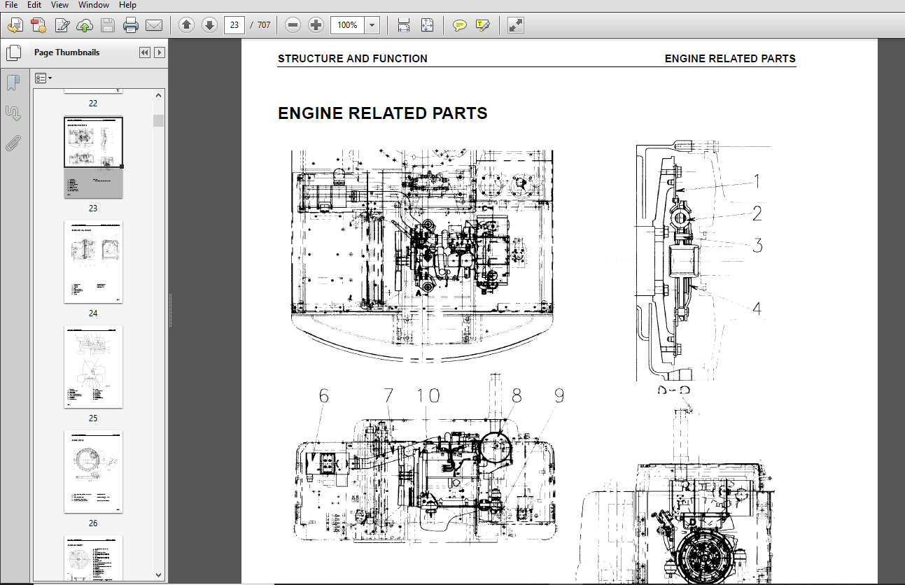
STRUCTURE AND FUNCTION:
This section explains the structure and function of each component. It serves not only to give an understanding of the structure, but also serves as reference material for troubleshooting.
TESTING AND ADJUSTING:
This section explains checks to be made before and after performing repairs , as well as adjustments to be made at completion of the checks and repairs. Troubleshooting charts correlating “problems” to “Causes” are also included in this section.
DISASSEMBLY AND ASSEMBLY:
This section explains the order to be followed when removing, installing, disassembling or assembling eachr component, as well as precautions to be taken for these operations.
MAINTENANCE STANDARD:
This section gives the judgement standards when inspecting disassembled parts.
TABLE OF CONTENTS:
Komatsu PW170ES-6K Hydraulic Excavator Shop Manual
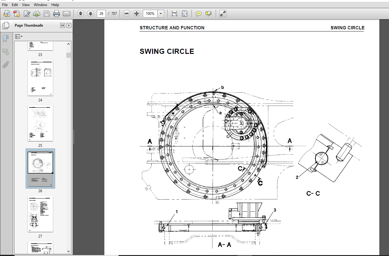
PW170ES- 6K ....................................................................................................................................................................  1
K32001 and up K34001 and up ....................................................................................................................................................  1
CONTENTS .......................................................................................................................................................................  2
01 GENERAL.........................................................Helvetica-Bold ..............................................................................................  2
10 STRUCTURE AND FUNCTION ......................................................................................................................................................  2
20 TESTING AND ADJUSTING .......................................................................................................................................................  2
30 DISASSEMBLY AND ASSEMBLY ....................................................................................................................................................  2
40 MAINTENANCE STANDARD.................................................. ......................................................................................................  2
SAFETY .........................................................................................................................................................................  6
	SAFETY NOTICE ..............................................................................................................................................................  6
FOREWORD .......................................................................................................................................................................  8
	GENERAL ....................................................................................................................................................................  8
HOW TO READ THE SHOP MANUAL ....................................................................................................................................................  9
HOISTING INSTRUCTIONS .......................................................................................................................................................... 10
COATING MATERIALS .............................................................................................................................................................. 11
STANDARD TIGHTENING TORQUE ..................................................................................................................................................... 12
ELECTRIC WIRE CODE ............................................................................................................................................................. 14
CONVERSION TABLE ............................................................................................................................................................... 15
ENGINE RELATED PARTS ........................................................................................................................................................... 23
RADIATOR Ł OIL COOLER .......................................................................................................................................................... 24
SWING CIRCLE ................................................................................................................................................................... 26
	SWING HOLDING BRAKE ........................................................................................................................................................ 28
SWING MACHINERY UNDERCARRIAGE .................................................................................................................................................. 30
CLUTCH CONTROL CIRCUIT ......................................................................................................................................................... 31
	FUNCTION ................................................................................................................................................................... 32
AXLE ........................................................................................................................................................................... 33
	REAR AXLE .................................................................................................................................................................. 34
	REAR AXLE .................................................................................................................................................................. 36
SUSPENSION LOCK CYLINDER ....................................................................................................................................................... 37
	CIRCUIT .................................................................................................................................................................... 38
BRAKING TRAIN .................................................................................................................................................................. 39
BRAKE PEDAL .................................................................................................................................................................... 40
BRAKE PEDAL INCORPORATING BRAKE VALVE .......................................................................................................................................... 41
ACCUMULATOR FOR BRAKE SYSTEM ................................................................................................................................................... 42
STEERING TRAIN ................................................................................................................................................................. 43
ITEM ........................................................................................................................................................................... 44
STEERING COLUMN ................................................................................................................................................................ 45
HYDRAULIC CIRCUIT DIAGRAM ...................................................................................................................................................... 46
HYDRAULIC CIRCUIT DIAGRAM ...................................................................................................................................................... 47
HYDRAULIC TANK ................................................................................................................................................................. 48
HYDRAULIC TANK ................................................................................................................................................................. 49
HYDRAULIC PUMP ................................................................................................................................................................. 51
	OPERATION .................................................................................................................................................................. 52
PPC PUMPLESS SYSTEM ............................................................................................................................................................ 68
CONTROL VALVE .................................................................................................................................................................. 70
CLSS ........................................................................................................................................................................... 80
POINTS TO REMEMBER WHEN TROUBLESHOOTING ........................................................................................................................................245
SEQUENCE OF EVENTS IN TROUBLESHOOTING ..........................................................................................................................................246
PRECAUTIONS WHEN CARRYING OUT MAINTENANCE ......................................................................................................................................247
	1. PRECAUTIONS WHEN HANDLING ELECTRIC EQUIPMENT ............................................................................................................................247
CHECKS BEFORE TROUBLESHOOTING ..................................................................................................................................................254
CONNECTOR TYPES ................................................................................................................................................................255
CONNECTION TABLE FOR CONNECTOR PIN NUMBERS .....................................................................................................................................259
EXPLANATION OF CONTROL MACHANISM FOR ELECTRICAL SYSTEM .........................................................................................................................272
METHOD OF USING JUDGEMENT TABLE ................................................................................................................................................281
METHOD OF USING TROUBLESHOOTING CHARTS .........................................................................................................................................283
DETAILS OF TROUBLESHOOTING AND TROUBLESHOOTING PROCEDURE .......................................................................................................................285
SERVICE CODE TABLE .............................................................................................................................................................290
POINTS TO REMEMBER WHEN CARRYING OUT TROUBLESHOOTING OF GOVERNOR, PUMP CONTROLLER SYSTEM .......................................................................................296
ACTION TAKEN BY CONTROLLER WHEN ABNORMALITY OCCURS AND PROBLEMS ON MACHINE .....................................................................................................297
JUDGEMENT TABLE FOR GOVERNOR, PUMP GOVERNOR ( GOVERNOR CONTROL SYSTEM) AND ENGINE RELATED PARTS ................................................................................301
ELECTRICAL CIRCUIT DIAGRAM FOR E MODE 1/ 2 .....................................................................................................................................303
ELECTRICAL CIRCUIT DIAGRAM FOR E MODE 2/ 2 .....................................................................................................................................304
E- 1 Abnormality in governor, pump controller power source ( controller LED is OFF) ............................................................................................305
E- 2 [ E308] Abnormality in fuel control dial input value is displayed .........................................................................................................306
E- 3 [ E317] Abnormality ( disconnection) in motor drive system is displayed ...................................................................................................307
E- 4 [ E318] Abnormality ( short circuit) in motor drive system is displayed ...................................................................................................308
E- 5 [ E306] Abnormality in feedback potentiometer system is displayed .........................................................................................................309
E- 6 [ E315] Abnormality ( short circuit) in battery relay output system is displayed ..........................................................................................310
E- 7 [ E316] Abnormality ( step- out) in motor is displayed ....................................................................................................................311
E- 8 Engine does not start .....................................................................................................................................................313
	Engine speed is irregular ..................................................................................................................................................315
	Defective operation of battery relay system ( engine does not stop) ........................................................................................................323
METHOD OF USING TROUBLESHOOTING CHARTS .........................................................................................................................................325
S- 1 Starting performance is poor ( starting always takes time) ................................................................................................................329
S- 2 Engine does not start .....................................................................................................................................................330
S- 3 Engine does not pick up smoothly ( follow- up is poor) ....................................................................................................................333
S- 4 Engine stops during operations ............................................................................................................................................334
S- 5 Engine does not rotate smoothly ( hunting) ................................................................................................................................335
S- 6 Engine lacks output ( no power) ...........................................................................................................................................336
S- 7 Exhaust smoke is black ( incomplete combustion) ...........................................................................................................................337
S- 8 Oil consumption is excessive ( or exhaust smoke is blue) ..................................................................................................................338
S- 9 Oil becomes contaminated quickly ..........................................................................................................................................339
S- 10 Fuel consumption is excessive ............................................................................................................................................340
S- 11 Oil is in cooling water, or water spurts back, or water level goes down ..................................................................................................341
S- 12 Oil pressure caution lamp lights up ( drop in oil pressure) ..............................................................................................................342
S- 13 Oil level rises ( water, fuel in oil) ....................................................................................................................................343
S- 14 Water temperature becomes too high ( overheating) ........................................................................................................................344
S- 15 Abnormal noise is made ...................................................................................................................................................345
S- 16 Vibration is excessive ...................................................................................................................................................346
ELECTRICAL CIRCUIT DIAGRAM FOR C MODE 1/ 2 ELECTRICAL CIRCUIT DIAGRAM FOR C MODE 2/ 2 ELECTRICAL CIRCUIT DIAGRAM FOR F MODE 1/ 2 ELECTRICAL CIRCUIT DIAGRAM FOR F MODE 2/ 2 ....380
PW170ES- 6K Serial number K32001 and up PW170ES- 6K Serial number K32001 and up INSTALLATION OF OPERATOR'S CAB ASSEMBLY ........................................................539
REMOVAL OF COUNTERWEIGHT ASSEMBLY ..............................................................................................................................................540
INSTALLATION OF COUNTERWEIGHT ASSEMBLY .........................................................................................................................................540
PW170ES- 6K ....................................................................................................................................................................  1
K32001 and up K34001 and up ....................................................................................................................................................  1
CONTENTS .......................................................................................................................................................................  2
01 GENERAL.........................................................Helvetica-Bold ..............................................................................................  2
10 STRUCTURE AND FUNCTION ......................................................................................................................................................  2
20 TESTING AND ADJUSTING .......................................................................................................................................................  2
30 DISASSEMBLY AND ASSEMBLY ....................................................................................................................................................  2
40 MAINTENANCE STANDARD.................................................. ......................................................................................................  2
SAFETY .........................................................................................................................................................................  6
	SAFETY NOTICE ..............................................................................................................................................................  6
FOREWORD .......................................................................................................................................................................  8
	GENERAL ....................................................................................................................................................................  8
HOW TO READ THE SHOP MANUAL ....................................................................................................................................................  9
HOISTING INSTRUCTIONS .......................................................................................................................................................... 10
COATING MATERIALS .............................................................................................................................................................. 11
STANDARD TIGHTENING TORQUE ..................................................................................................................................................... 12
ELECTRIC WIRE CODE ............................................................................................................................................................. 14
CONVERSION TABLE ............................................................................................................................................................... 15
ENGINE RELATED PARTS ........................................................................................................................................................... 23
RADIATOR Ł OIL COOLER .......................................................................................................................................................... 24
SWING CIRCLE ................................................................................................................................................................... 26
	SWING HOLDING BRAKE ........................................................................................................................................................ 28
SWING MACHINERY UNDERCARRIAGE .................................................................................................................................................. 30
CLUTCH CONTROL CIRCUIT ......................................................................................................................................................... 31
	STRUCTURE .................................................................................................................................................................. 31
	FUNCTION ................................................................................................................................................................... 32
AXLE ........................................................................................................................................................................... 33
	FRONT AXLE ................................................................................................................................................................. 33
	REAR AXLE .................................................................................................................................................................. 34
	FRONT AXLE ................................................................................................................................................................. 35
	REAR AXLE .................................................................................................................................................................. 36
SUSPENSION LOCK CYLINDER ....................................................................................................................................................... 37
	CIRCUIT .................................................................................................................................................................... 38
BRAKING TRAIN .................................................................................................................................................................. 39
BRAKE PEDAL .................................................................................................................................................................... 40
BRAKE PEDAL INCORPORATING BRAKE VALVE .......................................................................................................................................... 41
ACCUMULATOR FOR BRAKE SYSTEM ................................................................................................................................................... 42
STEERING TRAIN ................................................................................................................................................................. 43
ITEM ........................................................................................................................................................................... 44
STEERING COLUMN ................................................................................................................................................................ 45
HYDRAULIC CIRCUIT DIAGRAM ...................................................................................................................................................... 46
HYDRAULIC CIRCUIT DIAGRAM ...................................................................................................................................................... 47
HYDRAULIC TANK ................................................................................................................................................................. 48
HYDRAULIC TANK ................................................................................................................................................................. 49
HYDRAULIC PUMP ................................................................................................................................................................. 51
	OPERATION .................................................................................................................................................................. 52
	FUNCTION ................................................................................................................................................................... 57
PPC PUMPLESS SYSTEM ............................................................................................................................................................ 68
CONTROL VALVE .................................................................................................................................................................. 70
CLSS ........................................................................................................................................................................... 80
POINTS TO REMEMBER WHEN TROUBLESHOOTING ........................................................................................................................................245
SEQUENCE OF EVENTS IN TROUBLESHOOTING ..........................................................................................................................................246
PRECAUTIONS WHEN CARRYING OUT MAINTENANCE ......................................................................................................................................247
	1. PRECAUTIONS WHEN HANDLING ELECTRIC EQUIPMENT ............................................................................................................................247
	2. POINTS TO REMEMBER WHEN HANDLING HYDRAULIC EQUIPMENT ....................................................................................................................252
CHECKS BEFORE TROUBLESHOOTING ..................................................................................................................................................254
CONNECTOR TYPES ................................................................................................................................................................255
CONNECTION TABLE FOR CONNECTOR PIN NUMBERS .....................................................................................................................................259
EXPLANATION OF CONTROL MACHANISM FOR ELECTRICAL SYSTEM .........................................................................................................................272
	DISPLAY METHOD AND SPECIAL FUNCTIONS OF MONITOR PANEL ......................................................................................................................273
METHOD OF USING JUDGEMENT TABLE ................................................................................................................................................281
METHOD OF USING TROUBLESHOOTING CHARTS .........................................................................................................................................283
DETAILS OF TROUBLESHOOTING AND TROUBLESHOOTING PROCEDURE .......................................................................................................................285
SERVICE CODE TABLE .............................................................................................................................................................290
POINTS TO REMEMBER WHEN CARRYING OUT TROUBLESHOOTING OF GOVERNOR, PUMP CONTROLLER SYSTEM .......................................................................................296
ACTION TAKEN BY CONTROLLER WHEN ABNORMALITY OCCURS AND PROBLEMS ON MACHINE .....................................................................................................297
JUDGEMENT TABLE FOR GOVERNOR, PUMP GOVERNOR ( GOVERNOR CONTROL SYSTEM) AND ENGINE RELATED PARTS ................................................................................301
ELECTRICAL CIRCUIT DIAGRAM FOR E MODE 1/ 2 .....................................................................................................................................303
ELECTRICAL CIRCUIT DIAGRAM FOR E MODE 2/ 2 .....................................................................................................................................304
E- 1 Abnormality in governor, pump controller power source ( controller LED is OFF) ............................................................................................305
E- 2 [ E308] Abnormality in fuel control dial input value is displayed .........................................................................................................306
E- 3 [ E317] Abnormality ( disconnection) in motor drive system is displayed ...................................................................................................307
E- 4 [ E318] Abnormality ( short circuit) in motor drive system is displayed ...................................................................................................308
E- 5 [ E306] Abnormality in feedback potentiometer system is displayed .........................................................................................................309
E- 6 [ E315] Abnormality ( short circuit) in battery relay output system is displayed ..........................................................................................310
E- 7 [ E316] Abnormality ( step- out) in motor is displayed ....................................................................................................................311
E- 8 Engine does not start .....................................................................................................................................................313
	E- 9 Engine speed is irregular .............................................................................................................................................315
	E- 10 Lack of output ( engine high idling speed is too low) ................................................................................................................319
	E- 11 Engine does not stop .................................................................................................................................................321
	E- 12 Defective operation of battery relay system ( engine does not stop) ..................................................................................................323
METHOD OF USING TROUBLESHOOTING CHARTS .........................................................................................................................................325
S- 1 Starting performance is poor ( starting always takes time) ................................................................................................................329
S- 2 Engine does not start .....................................................................................................................................................330
S- 3 Engine does not pick up smoothly ( follow- up is poor) ....................................................................................................................333
S- 4 Engine stops during operations ............................................................................................................................................334
S- 5 Engine does not rotate smoothly ( hunting) ................................................................................................................................335
S- 6 Engine lacks output ( no power) ...........................................................................................................................................336
S- 7 Exhaust smoke is black ( incomplete combustion) ...........................................................................................................................337
S- 8 Oil consumption is excessive ( or exhaust smoke is blue) ..................................................................................................................338
S- 9 Oil becomes contaminated quickly ..........................................................................................................................................339
S- 10 Fuel consumption is excessive ............................................................................................................................................340
S- 11 Oil is in cooling water, or water spurts back, or water level goes down ..................................................................................................341
S- 12 Oil pressure caution lamp lights up ( drop in oil pressure) ..............................................................................................................342
S- 13 Oil level rises ( water, fuel in oil) ....................................................................................................................................343
S- 14 Water temperature becomes too high ( overheating) ........................................................................................................................344
S- 15 Abnormal noise is made ...................................................................................................................................................345
S- 16 Vibration is excessive ...................................................................................................................................................346
ELECTRICAL CIRCUIT DIAGRAM FOR C MODE 1/ 2 ELECTRICAL CIRCUIT DIAGRAM FOR C MODE 2/ 2 ELECTRICAL CIRCUIT DIAGRAM FOR F MODE 1/ 2 ELECTRICAL CIRCUIT DIAGRAM FOR F MODE 2/ 2 ....380
PW170ES- 6K Serial number K32001 and up PW170ES- 6K Serial number K32001 and up INSTALLATION OF OPERATOR'S CAB ASSEMBLY ........................................................539
REMOVAL OF COUNTERWEIGHT ASSEMBLY ..............................................................................................................................................540
INSTALLATION OF COUNTERWEIGHT ASSEMBLY .........................................................................................................................................540
REMOVAL OF GOVERNOR PUMP CONTROLLER ASSEMBLY ...................................................................................................................................541
INSTALLATION OF GOVERNOR, PUMP CONTROLLER ASSEMBLY .............................................................................................................................541
REMOVAL OF MONITOR PANEL ASSEMBLY ..............................................................................................................................................542
INSTALLATION OF MONITOR PANEL ASSEMBLY .........................................................................................................................................542
DISASSEMBLY OF SWING MACHINERY ASSEMBLY ( SPECIAL TOOLS FOR SWING MACHINERY) ( SPECIAL TOOLS FOR SWING MACHINERY) TRANSMISSION .................................................581
FRONT AXLE .....................................................................................................................................................................634
REAR AXLE ......................................................................................................................................................................652
ADAPTER WELDING INSTRUCTION - ELECTRODE WELDING ................................................................................................................................666
OUTRIGGER CYLINDER .............................................................................................................................................................669
	REMOVAL OF OUTRIGGER CYLINDER ..............................................................................................................................................669
	INSTALLATION OF OUTRIGGER CYLINDER .........................................................................................................................................669
BLADE CYLINDER .................................................................................................................................................................670
	REMOVAL OF BLADE CYLINDER ..................................................................................................................................................670
	INSTALLATION OF BLADE CYLINDER .............................................................................................................................................670
MAINTENANCE STANDARD ...........................................................................................................................................................672
	ENGINE MOUNT ...............................................................................................................................................................673
	SWING MACHINERY CONTROL VALVE SUCTION- SAFETY VALVE ........................................................................................................................685
	SWING MOTOR WORK EQUIPMENT, SWING PPC VALVE ................................................................................................................................687
	EPC SOLENOID VALVE .........................................................................................................................................................688
	CENTER SWIVEL JOINT ........................................................................................................................................................689
	ARM, BOOM SAFETY VALVE .....................................................................................................................................................690
	HYDRAULIC CYLINDER .........................................................................................................................................................691
	WORK EQUIPMENT .............................................................................................................................................................692
	WORK EQUIPMENT - ONE PIECE BOOM ............................................................................................................................................693
	WORK EQUIPMENT - TWO PIECE BOOM ............................................................................................................................................694
	DIMENSIONS OF WORK EQUIPMENT ...............................................................................................................................................696
	DOZER BLADE AND OUTRIGGERS HYDRAULIC CYLINDERS .............................................................................................................................700
	OUTRIGGER BUSH PINS ........................................................................................................................................................701
	TRANSMISSION ...............................................................................................................................................................702
	FRONT AXLE .................................................................................................................................................................703
	REAR AXLE ..................................................................................................................................................................704
	ARM ROTATION CIRCLE ........................................................................................................................................................705
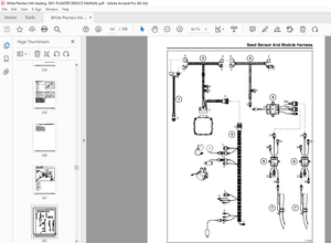
IMAGES PREVIEW OF THE MANUAL:
More products