$45
Komatsu PW180-7E0 Hydraulic Excavator Shop Manual - PDF DOWNLOAD
Komatsu PW180-7E0 Hydraulic Excavator Shop ManualFILE DETAILS:
Komatsu PW180-7E0 Hydraulic Excavator Shop Manual
File Format : PDF
Language : English
Printable : Yes
Searchable : Yes
Bookmarked : Yes
Product Code : VEBM400100
Total Pages : 1148
DESCRIPTION:
Komatsu PW180-7E0 Hydraulic Excavator Shop Manual
FOREWORD:
GENERAL:
This shop manual has been prepared as an aid to improve the quality of repairs by giving the serviceman an accurate understanding of the product and by showing him the correct way to perform repairs and make judgements. Make sure you understand the contents of this manual and use it to full effect at every opportunity. This shop manual mainly contains the necessary technical information for operations performed in a service workshop. For ease of understanding, the manual is divided into the following chapters; these chapters are further divided into the each main group of components.
STRUCTURE AND FUNCTION:
This section explains the structure and function of each component. It serves not only to give an understanding of the structure, but also serves as reference material for troubleshooting.
In addition, this section may contain hydraulic circuit diagrams, electric circuit diagrams, and maintenance standards.
TESTING AND ADJUSTING:
This section explains checks to be made before and after performing repairs, as well as adjustments to be made at completion of the checks and repairs. Troubleshooting charts correlating “Problems” with “Causes” are also included in this section.
DISASSEMBLY AND ASSEMBLY:
This section explains the procedures for removing, installing, disassembling and assembling each component, as well as precautions for them.
MAINTENANCE STANDARD:
This section gives the judgment standards for inspection of disassembled parts. The contents of this section may be described in STRUCTURE AND FUNCTION.
TABLE OF CONTENTS:
Komatsu PW180-7E0 Hydraulic Excavator Shop Manual
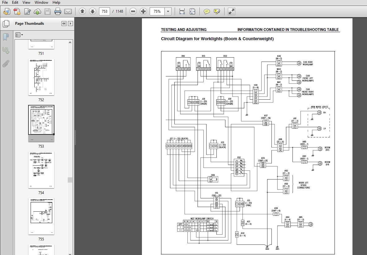
VEBM400100 PW180-E0..................................................................................................   1
SAFETY...............................................................................................................   3
	SAFETY NOTICE....................................................................................................   3
01 GENERAL...........................................................................................................  11
	SPECIFICATION DIMENSION DRAWINGS.................................................................................  28
		DIMENSIONS...................................................................................................  28
	WORKING RANGES...................................................................................................  32
		1 PIECE BOOM.................................................................................................  32
		2 PIECE BOOM.................................................................................................  33
	SPECIFICATIONS...................................................................................................  34
	FUEL, COOLANT AND LUBRICANTS.....................................................................................  39
	WEIGHT TABLE.....................................................................................................  36
		1 PIECE BOOM.................................................................................................  37
		2 PIECE BOOM.................................................................................................  38
	HOISTING INSTRUCTIONS............................................................................................  13
	HOW TO READ THE SHOP MANUAL......................................................................................  12
	COATING MATERIALS................................................................................................  14
	STANDARD TIGHTENING TORQUE.......................................................................................  16
		STANDARD TIGHTENING TORQUE OF BOLTS AND NUTS.................................................................  16
		TIGHTENING TORQUE OF HOSE NUTS...............................................................................  17
		TIGHTENING TORQUE OF SPLIT FLANGE BOLTS......................................................................  17
		TIGHTENING TORQUES FOR HOSES (Taper seal type and face seal type)............................................  17
		TIGHTENING TORQUE FOR 107 ENGINE SERIES (BOLTS AND NUTS).....................................................  18
		TIGHTENING TORQUE FOR 107 ENGINE SERIES (EYE JOINTS).........................................................  18
		TIGHTENING TORQUE FOR 107 ENGINE SERIES (TAPERED SCREWS).....................................................  18
	ELECTRIC WIRE CODE...............................................................................................  19
		CLASSIFICATION BY THICKNESS..................................................................................  19
		CLASSIFICATION BY COLOR AND CODE.............................................................................  19
	CONVERSION TABLES................................................................................................  20
		METHOD OF USING THE CONVERSION TABLE.........................................................................  20
	UNITS............................................................................................................  26
		DIMENSIONS...................................................................................................  30
		2 PIECE BOOM.................................................................................................  30
10 STRUCTURE, FUNCTION AND MAINTENANCE ..............................................................................  41
	ENGINE RELATED PARTS.............................................................................................  42
	RADIATOR . OIL COOLER . CHARGE AIR COOLER........................................................................  43
	POWER TRAIN......................................................................................................  44
	SWING CIRCLE.....................................................................................................  46
	SWING MACHINERY & MOTOR..........................................................................................  47
	SWING MOTOR......................................................................................................  50
		Operation of swing lock......................................................................................  54
		RELIEF VALVE PORTION.........................................................................................  55
	UNDERCARRIAGE....................................................................................................  56
	TRANSMISSION.....................................................................................................  58
	TRAVEL MOTOR.....................................................................................................  62
		OPERATION OF TRAVEL MOTOR....................................................................................  64
	CLUTCH CONTROL CIRCUIT...........................................................................................  66
	AXLE.............................................................................................................  68
	SUSPENSION LOCK CYLINDER.........................................................................................  72
	BRAKING SYSTEM...................................................................................................  74
	BRAKE/STEER PUMP.................................................................................................  76
	PRIORITY VALVE...................................................................................................  77
	POWER BRAKE VALVE................................................................................................  78
	ACCUMULATOR FOR BRAKE VALVE......................................................................................  80
	STEERING SYSTEM..................................................................................................  81
	STEERING COLUMN..................................................................................................  82
	ORBITROL VALVE...................................................................................................  83
	HYDRAULIC EQUIPMENT LAYOUT DRAWINGS..............................................................................  84
	HYDRAULIC CIRCUIT DIAGRAM........................................................................................  86
	HYDRAULIC TANK...................................................................................................  87
	HYDRAULIC PUMP...................................................................................................  89
		LS VALVE.....................................................................................................  94
		PC VALVE.....................................................................................................  95
		LS(PC)-EPC VALVE............................................................................................. 109
	PILOT PRESSURE CONTROL (PPC) SYSTEM.............................................................................. 113
	CONTROL VALVE.................................................................................................... 115
		PW180-7E0.................................................................................................... 115
	CLSS............................................................................................................. 126
		OUTLINE OF CLSS.............................................................................................. 126
		BASIC PRINCIPLE.............................................................................................. 127
		OPERATION FOR EACH FUNCTION AND VALVE........................................................................ 129
		1. Unload valve.............................................................................................. 131
		2. Introduction of LS pressure............................................................................... 134
		3. LS Bypass plug............................................................................................ 135
		4. Pressure compensation valve............................................................................... 137
		5. Area ratio of pressure compensation valve................................................................. 139
		6. Boom regeneration circuit................................................................................. 141
		7. Arm regeneration circuit.................................................................................. 143
		8. Swing bleeding valve...................................................................................... 145
		9. Variable type pressure compensation valve (for service)................................................... 146
		10. LS select valve.......................................................................................... 147
	CENTRE SWIVEL JOINT.............................................................................................. 148
	TRAVEL PPC PEDAL................................................................................................. 149
	WORK EQUIPMENT . SWING PPC VALVE................................................................................. 151
	SOLENOID VALVE BLOCK............................................................................................. 157
		SOLENOID VALVE BLOCK......................................................................................... 159
	BOOM SAFETY VALVE................................................................................................ 166
	HYDRAULIC CYLINDER............................................................................................... 168
	OUTRIGGER CYLINDER............................................................................................... 170
	DOZER CYLINDER................................................................................................... 172
	WORK EQUIPMENT................................................................................................... 174
		Work Equipment............................................................................................... 175
		1. DIMENSION OF ARM.......................................................................................... 176
	AIR CONDITIONER.................................................................................................. 180
		AIR CONDITIONER PIPING....................................................................................... 180
	ELECTRICAL WIRING DIAGRAM........................................................................................ 181
	ELECTRICAL SYSTEM................................................................................................ 182
	ELECTRONIC CONTROL SYSTEM........................................................................................ 188
		MACHINE CONTROL SYSTEM DIAGRAM............................................................................... 189
	MACHINE MONITOR SYSTEM........................................................................................... 213
	OVERLOAD WARNING DEVICE.......................................................................................... 241
		OUTLINE...................................................................................................... 241
	SENSOR........................................................................................................... 242
	1st ATTACHMENT CIRCUIT HYDRAULIC PERFORMANCE (MAIN VALVE BYPASSED)............................................... 251
	TRAVEL SYSTEM.................................................................................................... 252
		TRAVEL CIRCUIT............................................................................................... 252
		OPERATIONAL AND CONTROL FEATURES............................................................................. 253
	STEERING SYSTEM.................................................................................................. 271
		OPERATING PRINCIPLES......................................................................................... 271
	SERVICE BRAKE AND SUSPENSION SYSTEM.............................................................................. 284
		BRAKING SYSTEM............................................................................................... 284
		OPERATION.................................................................................................... 287
20 TESTING AND ADJUSTING............................................................................................. 289
	STANDARD VALUE TABLE FOR ENGINE RELATED PARTS.................................................................... 290
	STANDARD VALUE TABLE FOR CHASSIS RELATED PARTS................................................................... 291
		Flow control characteristic of PC valve (STD)................................................................ 303
	MEASURING ENGINE SPEED........................................................................................... 306
	MEASURING INTAKE AIR PRESSURE (BOOST PRESSURE)................................................................... 307
	MEASUREMENT OF EXHAUST GAS COLOUR................................................................................ 308
	ADJUSTING VALVE CLEARANCE........................................................................................ 310
	MEASURING COMPRESSION PRESSURE................................................................................... 312
	MEASURING BLOW-BY PRESSURE....................................................................................... 314
	MEASURING ENGINE OIL PRESSURE.................................................................................... 315
	HANDLING FUEL SYSTEM PARTS....................................................................................... 316
	RELEASING RESIDUAL PRESSURE FROM FUEL SYSTEM..................................................................... 317
	MEASURING FUEL PRESSURE.......................................................................................... 318
	MEASURING FUEL RETURN RATE AND LEAKAGE........................................................................... 320
	BLEEDING AIR FROM FUEL CIRCUIT................................................................................... 322
		Checking fuel circuit for leakage............................................................................ 324
	CHECKING AND ADJUSTING AIR CONDITIONER COMPRESSOR BELT TENSION................................................... 325
	MEASUREMENT OF CLEARANCE IN SWING CIRCLE BEARINGS................................................................ 326
	INSPECTION AND ADJUSTMENT OF HYDRAULIC OIL PRESSURE IN HYDRAULIC CIRCUIT FOR WORK EQUIPMENT, SWING AND TRAVEL.... 327
	INSPECTION AND ADJUSTMENT OF CONTROL CIRCUIT OIL PRESSURE........................................................ 330
	INSPECTION AND ADJUSTMENT OF PUMP PC (VALVE INLET) CONTROL OIL PRESSURE.......................................... 332
	INSPECTION AND ADJUSTMENT OF PUMP LS VALVE CONTROL OIL PRESSURE.................................................. 335
	MEASUREMENT OF SOLENOID VALVE OUTPUT PRESSURE.................................................................... 339
		Solenoid valve block......................................................................................... 341
	MEASUREMENT OF PPC VALVE OUTPUT PRESSURE......................................................................... 344
	ADJUSTMENT OF WORK EQUIPMENT AND SWING PPC VALVE................................................................. 346
	TESTING TRAVEL MOTOR RELIEF PRESSURE............................................................................. 347
	ADJUSTING TRAVEL MOTOR RELIEF PRESSURE........................................................................... 348
		TESTING PROPSHAFT SPEED...................................................................................... 349
	TESTING TRANSMISSION CLUTCH CONTROL CIRCUIT...................................................................... 350
	INSPECTION OF LOCATIONS OF HYDRAULIC DRIFT OF WORK EQUIPMENT..................................................... 352
		RELEASE OF REMAINING PRESSURE IN HYDRAULIC CIRCUIT........................................................... 354
	MEASUREMENT OF OIL LEAKAGE....................................................................................... 355
	AIR BLEEDING OF VARIOUS PARTS.................................................................................... 358
	INSPECTION PROCEDURES FOR DIODE.................................................................................. 361
	SPECIAL FUNCTION OF MONITOR PANEL................................................................................ 363
		OPERATION OF OPERATORS MENU AND DISPLAY (OUTLINE)............................................................ 365
		TABLE FOR FAILURE CODE NO.................................................................................... 372
		OPERATION AND DISPLAY OF SERVICE MENU........................................................................ 375
			Way of switching to Service Menu......................................................................... 375
			Table for Monitoring Items............................................................................... 378
	PREPARATIONS FOR TROUBLESHOOTING ELECTRICAL SYSTEM............................................................... 395
	POINTS TO REMEMBER WHEN TROUBLESHOOTING.......................................................................... 398
	SEQUENCE OF EVENTS IN TROUBLESHOOTING............................................................................ 399
	POINTS TO REMEMBER WHEN CARRYING OUT MAINTENANCE................................................................. 400
	CLASSIFICATION AND STEPS FOR TROUBLESHOOTING..................................................................... 410
		Classification of troubleshooting............................................................................ 410
			Steps for troubleshooting................................................................................ 410
		Failure-looking Phenomenon and Troubleshooting No............................................................ 411
		How to read electric wire code............................................................................... 414
	CONNECTOR LOCATION CHART AND ELECTRICAL CIRCUIT DIAGRAM BY SYSTEM................................................ 417
		CONNECTOR LOCATIONS.......................................................................................... 424
	CONNECTION TABLE FOR CONNECTOR PIN NUMBERS....................................................................... 446
		T-boxes and T-adapters table................................................................................. 474
		Before carrying out troubleshooting when failure code is displayed........................................... 481
	INFORMATION CONTAINED IN TROUBLESHOOTING TABLE................................................................... 482
		Relative Electrical Circuit Diagram.......................................................................... 483
		Failure Code [6B2JMA] (Abnormality in travel PPC switch hydraulics).......................................... 484
		Failure code [989L00] Engine Controller Lock Caution 1....................................................... 485
		Failure code [989M00] Engine Controller Lock Caution 2....................................................... 485
		Failure code [989N00] Engine Controller Lock Caution 3....................................................... 486
		Failure code [AA10NX] Air Cleaner Clogging................................................................... 486
		Failure code [AB00KE] Charge Voltage Low..................................................................... 487
		Failure code [B@BAZG] Eng Oil Press. Low..................................................................... 488
		Failure code [B@BAZK] Eng Oil Level Low...................................................................... 488
		Failure code [B@BCNS] Eng Water Overheat..................................................................... 489
		Failure code [B@BCZK] Eng Water Level Low.................................................................... 489
		Failure code [B@HANS] Hydr Oil Overheat...................................................................... 490
		Failure code [CA111] EMC Critical Internal Failure........................................................... 490
		Failure code [CA115] Engine Neutral and Backup Speed Sensor Error............................................ 491
		Failure code [CA122] Chg Air Press Sensor High Error......................................................... 492
		Failure code [CA123] Chg Air Press Sensor Low Error.......................................................... 494
		Failure code [CA131] Throttle Sensor High Error.............................................................. 496
		Failure code [CA132] Throttle Sensor Low Error............................................................... 498
		Failure code [CA144] Coolant Temp Sens High Error............................................................ 500
		Failure code [CA145] Coolant Temp Sens Low Error............................................................. 502
		Failure code [CA153] Chg Air Temp Sensor High Error.......................................................... 504
		Failure code [CA154] Chg Air Temp Sensor Low Error........................................................... 506
		Failure code [CA155] Chg Air Temp High Speed Derate.......................................................... 508
		Failure code [CA187] Sens Supply 2 Volt Low Error............................................................ 510
		Failure code [CA221] Ambient Press Sens High Error........................................................... 512
		Failure code [CA222] Ambient Press Sens Low Error............................................................ 514
		Failure code [CA227] Sens Supply 2 Volt High Error........................................................... 516
		Failure code [CA234] Eng Overspeed........................................................................... 517
		Failure code [CA238] Ne Speed Sens Supply Volt Error......................................................... 518
		Failure code [CA271] IMV/PCV1 Short Error.................................................................... 519
		Failure code [CA272] IMV/PCV1 Open Error..................................................................... 520
		Failure code [CA322] Inj #1 (L#1) Open/Short Error........................................................... 522
		Failure code [CA323] Inj #5 (L#5) Open/Short Error........................................................... 524
		Failure code [CA324] Inj #3 (L#3) Open/Short Error........................................................... 526
			Failure code [CA325] Inj #6 (L#6) Open/Short Error....................................................... 528
		Failure code [CA331] Inj #2 (L#2) Open/Short Error........................................................... 530
		Failure code [CA332] Inj #4 (L#4) Open/Short Error........................................................... 532
		Failure code [CA342] Calibration Code Incompatibility........................................................ 534
			Failure code [CA351] Injectors Drive Circuit Error....................................................... 536
		Failure code [CA352] Sens Supply 1 Volt Low Error............................................................ 538
		Failure code [CA386] Sens Supply 1 Volt High Error........................................................... 540
		Failure code [CA428] Water in Fuel Sensor High Error......................................................... 542
			Failure code [CA429] Water in Fuel Sensor Low Error...................................................... 544
		Failure code [CA435] Eng Oil Press Sw Error.................................................................. 546
		Failure code [CA441] Battery Voltage Low Error............................................................... 547
		Failure code [CA442] Battery Voltage High Error.............................................................. 550
		Failure code [CA449] Rail Press Very High Error.............................................................. 552
		Failure code [CA451] Rail Press Sensor High Error............................................................ 554
		Failure code [CA452] Rail Press Sensor Low Error............................................................. 556
		Failure code [CA488] Chg Air Temp High Torque Derate......................................................... 558
		Failure code [CA553] Rail Press High Error................................................................... 558
		Failure code [CA559] Rail Press Low Error.................................................................... 559
		Failure code [CA689] Eng Ne Speed Sensor Error............................................................... 562
		Failure code [CA731] Eng Bkup Speed Sens Phase Error......................................................... 564
		Failure code [CA757] All Continuous Data Lost Error.......................................................... 566
		Failure code [CA778] Eng G Speed Sensor Error................................................................ 568
		Failure code [CA1633] KOMNET Datalink Timeout Error.......................................................... 570
		Failure code [CA2185] Throttle Sensor Supply Voltage High Error.............................................. 572
		Failure code [CA2186] Throttle Sensor Supply Voltage Low Error............................................... 573
		Failure code [CA2249] Rail Press Very Low Error.............................................................. 574
		Failure code [CA2311] IMV Solenoid Error..................................................................... 576
		Failure code [CA2555] Grid Htr Relay Volt High Error......................................................... 578
		Failure code [CA2556] Grid Heater Relay Volt Low Error....................................................... 580
		Failure Code [D110KB] (Short-circuiting in battery relay).................................................... 582
		Failure code [D19JKZ] Personal Code Relay Abnormality........................................................ 584
		Failure code [DA25KP] Press. Sensor Power Abnormality........................................................ 586
		Failure code [DA2RMC] Pump Comm. Abnormality................................................................. 588
		Failure Code [DA2SKQ] (Abnormality in inputting model code).................................................. 590
		Failure Code [DA2SKQ] (Abnormality in inputting model code).................................................. 592
		Failure code [DAFRMC] Monitor Comm. Abnormality.............................................................. 594
		Failure Code [DDHPAKP] (Abnormality in pump pressure sensor)................................................. 596
		Failure Code [DDP4KX] (Abnormality in travel PPC pressure switch)............................................ 598
		Failure Code [DDWCKZ] (Abnormality in travel direction control switch)....................................... 599
			Electrical Circuit Diagram for Travel PPC Switch......................................................... 599
		Failure Code [DH1OKS] (Abnormality in Pressure sensor power source).......................................... 600
		Failure code [DHPAMA] F Pump Press Sensor Abnormality........................................................ 602
		Failure Code [DHS5KX] (Abnormality in travel PPC sensor)..................................................... 604
		Failure Code [DHX1MA] (Abnormality in overload caution sensor)............................................... 606
		Failure Code [DLT4KA] (Disconnection in transmission speed sensor in pump controller system)................. 608
		Failure Code [DW27KA] (Disconnection in Transmission Clutch solenoid)........................................ 610
		Failure Code [DW27KB] (Short-circuiting in Transmission Clutch solenoid)..................................... 612
		Failure Code DW4AKA (Disconnection in suspension lock solenoid).............................................. 614
		Failure Code [DW4AKB] (Short circuiting in suspension lock solenoid)......................................... 616
		Failure Code [DW4CKA] (Disconnection in PPC lock solenoid)................................................... 618
		Failure code [DW4CKB] PPC Lock Sol. S/C...................................................................... 620
		Failure Code [DW4MKA] (Disconnection in Creep solenoid)...................................................... 622
			Electrical Circuit Diagram for Creep Solenoid in Pump Controller......................................... 623
		Failure Code [DW4MKB] (Short-circuiting in Creep solenoid)................................................... 624
			Electrical Circuit Diagram for Creep Solenoid in Pump Controller......................................... 625
		Failure Code [DW44KA] (Disconnection of Travel F/R solenoid)................................................. 626
		Failure Code [DW44KB] (Short-circuiting of Travel F/R solenoid).............................................. 628
		Failure Code [DW45KA] (Disconnection in Swing Parking Brake solenoid)........................................ 630
		Failure code [DW45KB] Swing Brake Sol. S/C................................................................... 632
		Failure Code [DW91KA] (Disconnection in Travel Neutral solenoid)............................................. 634
		Failure Code [DW91KB] (Short-circuiting in Travel Neutral Solenoid).......................................... 636
		Failure Code [DWK0KB] (Short-circuiting in 2-Stage Relief Solenoid).......................................... 640
		Failure Code [DWK2KA] (Disconnection in 2-stage Back Pressure solenoid)...................................... 642
		Failure Code [DWK2KB] (Short circuiting in 2-stage back pressure solenoid)................................... 644
		Failure Code [DXA0KA] (Disconnection in PC-EPC solenoid system).............................................. 646
		Failure Code [DXA0KB] (Short-circuiting in PC-EPC solenoid).................................................. 648
		Failure Code [DXE0KA] (Disconnection in LS-EPC solenoid system).............................................. 650
		Failure Code [DXE0KB] (Short-circuiting in LS-EPC solenoid).................................................. 651
		Failure Code [DXE4KA] (Disconnection in attachment oil flow rate adjusting EPC).............................. 652
			1st Service EPC Solenoid (Left Hand)..................................................................... 652
			1st Service EPC Solenoid (Right Hand).................................................................... 653
			2nd Service EPC Solenoid (Left Hand)..................................................................... 654
			2nd Service EPC Solenoid (Right Hand).................................................................... 655
		Failure Code [DXE4KB] (Short-circuiting in attachment oil flow rate adjusting EPC)........................... 657
			1st Service EPC Solenoid (Left Hand)..................................................................... 657
			1st Service EPC Solenoid (Right Hand).................................................................... 658
			2nd Service EPC Solenoid (Left Hand)..................................................................... 659
			2nd Service EPC Solenoid (Right Hand).................................................................... 660
		Failure code [DY20KA] Wiper Working Abnormality.............................................................. 662
		Failure code [DY20MA] Wiper Parking Abnormality.............................................................. 664
		Failure code [DY2CKB] Washer Drive S/C....................................................................... 666
		Failure code [DY2DKB] Wiper Drive (For) S/C.................................................................. 668
		Failure code [DY2EKB] Wiper Drive (Rev) S/C.................................................................. 670
	INFORMATION CONTAINED IN TROUBLESHOOTING TABLE................................................................... 674
		Relative Electrical Circuit Diagram.......................................................................... 675
		E-1 Engine does not start (Engine does not rotate)........................................................... 676
			Electrical Circuit Diagram for Engine Start, Stop and Battery Charging................................... 679
		E-5 Auto-decelerator does not work........................................................................... 680
		E-6 Auto engine warm-up device does not work................................................................. 682
		E-7 Preheater does not operate............................................................................... 684
		E-8 All work equipment, swing and travel do not move......................................................... 686
			Electrical Circuit Diagram for PPC Lock Solenoid......................................................... 687
		E-9 One-touch Power Max Switch does not work................................................................. 688
			Electric Circuit Diagram for One-Touch Power Max. Switch................................................. 688
		E-10 No display in monitor panel at all...................................................................... 689
			Electrical Circuit Diagram for Power Source in Monitor Panel............................................. 689
		E-11 Part of display on monitor panel is missing............................................................. 690
		E-12 Monitor panel displays contents irrelevant to the model................................................. 690
		E-13 Fuel level monitor red lamp lights up while engine is running........................................... 691
			Electrical Circuit Diagram for Fuel Level Sensor......................................................... 691
			E14 Engine coolant temperature gauge does not indicate normally.......................................... 692
		E-15 Hydraulic oil temperature gauge does not display correctly.............................................. 694
			Electrical Circuit Diagram for Hydraulic Oil Temperature Sensor.......................................... 694
		E-16 Fuel gauge does not display correctly................................................................... 695
			Electrical Circuit Diagram for Fuel Level Sensor......................................................... 695
		E-17 Swing lock monitor does not display correctly........................................................... 696
			Electrical Circuit Diagram for Swing Lock Switch......................................................... 697
		E-18 When the monitor switch is operated, no display appears................................................. 698
		E-19 Windshield wiper and window washer do not operate....................................................... 700
		E-20 Alarm buzzer cannot be stopped.......................................................................... 702
		E-21 "Boom/Stabiliser RAISE" is not correctly displayed in monitor function.................................. 704
			Electrical Circuit Diagram for Boom RAISE PPC Hydraulic Switch........................................... 704
		E-22 "Boom/Stabiliser LOWER" is not correctly displayed in monitor function.................................. 705
			Electrical Circuit Diagram for Boom LOWER PPC Hydraulic Switch........................................... 705
		E-23 "Arm DIGGING" is not correctly displayed in monitor function............................................ 706
			Electrical Circuit Diagram for Arm DIGGING PPC Hydraulic Switch.......................................... 706
		E-24 "Arm DUMPING" is not correctly displayed in monitor function............................................ 707
			Electrical Circuit Diagram for Arm DUMPING PPC Hydraulic Switch.......................................... 707
		E-25 "Bucket DIGGING" is not correctly displayed in monitor function......................................... 708
			Electrical Circuit Diagram for Bucket DIGGING PPC hydraulic Switch....................................... 708
		E-26 "Bucket DUMPING" is not correctly displayed in monitor function......................................... 709
			Electrical Circuit Diagram for Bucket DUMPING PPC hydraulic Switch....................................... 709
		E-27 "SWING" is not correctly displayed in monitor function.................................................. 710
			Electrical Circuit Diagram for Right and Left Swing PPC hydraulic Switches............................... 711
		E-28 "TRAVEL" is not correctly displayed in monitor function................................................. 712
			Electrical Circuit Diagram for Travel PPC hydraulic Switch and Travel Alarm.............................. 713
		E-29 "2 Piece Boom" is not correctly displayed in monitor function........................................... 714
			Electrical Circuit Diagram for 2 Pice Boom PPC hydraulic Switch.......................................... 715
		E-30 Air Conditioner does not work........................................................................... 716
			Electrical Circuit Diagram for Air Conditioner........................................................... 717
		E-31 Travel reverse alarm does not sound..................................................................... 718
			Electrical Circuit Diagram for Travel Reverse Alarm System............................................... 719
		E-32 KOMTRAX system does not operate normally................................................................ 720
	TROUBLESHOOTING OF ELECTRICAL SYSTEM (Error checking of items without Monitor codes)............................. 723
		INFORMATION CONTAINED IN TROUBLESHOOTING TABLE............................................................... 724
			Relative Electrical Circuit Diagram...................................................................... 725
			Radio Cassette & Telephone Socket........................................................................ 726
				Electrical Circuit Diagram For Radio Cassette & Telephone Socket..................................... 727
			PPC Lock Circuit......................................................................................... 728
				Circuit Diagram for PPC Lock Circuit................................................................. 729
			Brake Light Circuit...................................................................................... 730
				Circuit Diagram for Brake Light Circuit.............................................................. 731
			Undercarriage Attachments - Mode Selection............................................................... 732
				Circuit Diagram for Undercarriage Attachments - Mode Selection....................................... 733
			Undercarriage Attachments - Front Left Outrigger......................................................... 734
				Circuit Diagram for Undercarriage Attachments - Front Left Outrigger................................. 735
			Undercarriage Attacments - Front Right Outrigger......................................................... 736
				Circuit Diagram for Undercarriage Attachments - Front Right Outrigger................................ 737
			Undercariage Attachments - Rear Left Outrigger........................................................... 738
			Undercarriage Attachments - Rear Right Outrigger......................................................... 740
				Circuit Diagram for Undercarriage Attachments - Rear Right Outrigger................................. 741
			Heated Seat Does Not Warm Up............................................................................. 742
				Circuit Diagram for the Heated Seat.................................................................. 743
			Suspension Lock.......................................................................................... 744
				Circuit Diagram for Suspension Lock.................................................................. 745
			Lower Wiper Does Not Work (Optional Fitment)............................................................. 746
				Circuit Diagram for Lower Wiper...................................................................... 747
			Work Lights (Operator Cab Front Left).................................................................... 748
			Work Lights (Operator Cab Front Right)................................................................... 749
			Work Lights (Operator Cab Rear).......................................................................... 750
				Circuit Diagram for Work Lights...................................................................... 751
			Worklights (Boom, Arm & Counterweight)................................................................... 752
				Circuit Diagram for Worklights (Boom & Counterweight)................................................ 753
			Cab and Counterweight Beacon Light....................................................................... 754
				Circuit Diagram for Cab & Counterweight Beacon Light................................................. 755
			Air Seat Compressor (Option - Air Suspension Seat)....................................................... 756
				Circuit Diagram for Air Seat Compressor (Option - Air Suspension Seat)............................... 757
			Operator Cab Interior Light.............................................................................. 758
				Circuit Diagram for Operator Cab Interior Light...................................................... 759
			Cigar Lighter............................................................................................ 760
				Circuit Diagram for Cigar Lighter.................................................................... 761
			Park Brake (Not Activating).............................................................................. 762
				Circuit Diagram for Park Brake....................................................................... 763
			Park Brake (Displayed Symbol)............................................................................ 764
				Circuit Diagram for Park Brake....................................................................... 765
			RH PPC Lever Clamshell Roller Switch Pushed to the LH Position........................................... 766
				Circuit Diagram for Clamshell Control................................................................ 767
			RH PPC Lever Clamshell Roller Switch Pushed to the RH Position........................................... 768
				Circuit Diagram for Clamshell Control................................................................ 769
			RH PPC Lever Clamshell Roller Switched Pushed to the RH or LH............................................ 770
				Circuit Diagram for Clamshell Control................................................................ 771
			Horns.................................................................................................... 772
				Circuit Diagram for Horn............................................................................. 773
			Swing Lock - Normal Operation............................................................................ 774
				Circuit Diagram for Swing Lock....................................................................... 775
			Swing Lock - Emergency Operation......................................................................... 776
				Circuit Diagram for Swing Lock - Emergency Operation................................................. 777
			Neutral Start (Engine)................................................................................... 778
			Neutral Start (Engine) cont’d (A)........................................................................ 779
			Neutral Start (Engine) cont’d (B)........................................................................ 780
			Neutral Start (Engine) cont’d (C)........................................................................ 781
				Circuit Diagram for Neutral Start (Engine)........................................................... 782
			Emergency Travel Control - Forward....................................................................... 784
				Circuit Diagram for Travel Direction Control......................................................... 785
			Emergency Travel Control - Neutral....................................................................... 786
				Circuit Diagram for Travel Direction Control......................................................... 787
			Emergency Travel Control - Reverse....................................................................... 788
			Emergency Travel Control - Reverse cont’d................................................................ 789
				Circuit Diagram for Travel Direction Control......................................................... 790
			Driving Lights - Main Beam............................................................................... 792
				Circuit Diagram for Driving Lights................................................................... 793
			Driving Lights - Main Beam Flash......................................................................... 794
				Circuit Diagram for Driving Lights................................................................... 795
			Driving Lights - Main Beam Dipped........................................................................ 796
				Circuit Diagram for Driving Lights................................................................... 797
			Driving Lights - Position Lights......................................................................... 798
				Circuit Diagram for Driving Lights................................................................... 799
			Driving Lights - Position Lights cont’d (1) and (2)...................................................... 800
				Circuit Diagram for Driving Lights................................................................... 801
			Indicators - Right Hand.................................................................................. 802
				Circuit Diagram for Indicators & Hazard Warning...................................................... 803
			Indicators - Left Hand................................................................................... 804
				Circuit Diagram for Indicators & Hazard Warning...................................................... 805
			Hazard Warning Lights.................................................................................... 806
				Circuit Diagram for Indicators & Hazard Warning...................................................... 807
			Hazard Warning Lights cont’d (A)......................................................................... 808
				Circuit Diagram for Indicators & Hazard Warning...................................................... 809
			Swing Lock Proximity Switch.............................................................................. 810
				Brake and Swing Lock Proximity Switches.............................................................. 811
		SYSTEM CHART FOR HYDRAULIC AND MECHANICAL SYSTEMS............................................................ 815
		INFORMATION CONTAINED IN TROUBLESHOOTING TABLE............................................................... 819
			H-1 All work equipment lacks power, or travel and swing speeds are slow.................................. 820
			H-2 Engine speed sharply drops or engine stalls.......................................................... 821
			H-3 No work equipment, travel or swing move.............................................................. 822
			H-4 Abnormal noise is heard from around hydraulic pump................................................... 822
			H-5 Auto-decelerator does not work....................................................................... 823
			H-6 Fine control mode does not function.................................................................. 823
			H-7 Boom moves slowly or lacks power..................................................................... 824
			H-8 Arm moves slowly or lacks power...................................................................... 825
			H-9 Bucket moves slowly or lacks power................................................................... 826
			H-10 Work equipment does not move in its single operation................................................ 826
			H-11 Work equipment hydraulic drift is too fast.......................................................... 827
			H-12 Work equipment has big time lag..................................................................... 828
			H-13 Other work equipment moves when relieving single circuit............................................ 828
			H-14 One-touch power max. switch does not operate........................................................ 829
			H-15 In compound operation, work equipment with larger load moves slowly................................. 829
			H-16 In swing + boom RAISE operation, boom moves slowly.................................................. 829
			H-17 In swing + travel, travel speed drops sharply....................................................... 830
			H-18 Travel speed does not switch........................................................................ 831
			H-19 Travel speed does not shift, or it is too slow or fast.............................................. 832
			H-20 Machine does not swing.............................................................................. 833
			H-21 Swing acceleration is poor, or swing speed is slow.................................................. 834
			H-22 Excessive overrun when stopping swing............................................................... 835
			H-23 There is big shock when stopping swing.............................................................. 836
			H-24 There is loud abnormal noise caused when stopping swing............................................. 836
			H-25 Swing natural drift is too big...................................................................... 837
			H-26 Swing speed is faster than specified swing speed.................................................... 837
			Troubleshooting of engine (S-mode)....................................................................... 838
				Method of using troubleshooting chart................................................................ 838
			S-1 Starting performance is poor......................................................................... 841
			S-2 Engine does not start................................................................................ 842
			S-3 Engine does not pick up smoothly..................................................................... 845
			S-4 Engine stops during operations....................................................................... 846
			S-5 Engine does not rotate smoothly...................................................................... 847
			S-6 Engine lack output (or lacks power).................................................................. 848
			S-7 Exhaust smoke is black (incomplete combustion)....................................................... 849
			S-8 Oil consumption is excessive (or exhaust smoke is blue).............................................. 850
			S-9 Oil becomes contaminated quickly..................................................................... 851
			S-10 Fuel consumption is excessive....................................................................... 852
			S-11 Oil is in coolant (or coolant spurts back or coolant level goes down)............................... 853
			S-12 Oil pressure drops.................................................................................. 854
			S-13 Oil level rises (Entry of coolant/fuel)............................................................. 855
			S-14 Coolant temperature becomes too high (overheating).................................................. 856
			S-15 Abnormal noise is made.............................................................................. 857
			S-16 Vibration is excessive.............................................................................. 858
30 DISASSEMBLY AND ASSEMBLY.......................................................................................... 859
	HOW TO READ THIS MANUAL.......................................................................................... 864
		REMOVAL AND INSTALLATION OF ASSEMBLIES....................................................................... 864
		DISASSEMBLY AND ASSEMBLY OF ASSEMBLIES....................................................................... 865
			Coating materials list................................................................................... 866
			Special tools list....................................................................................... 869
			Sketches of special tools................................................................................ 872
			LIST OF TOOLS............................................................................................ 873
		PRECAUTIONS WHEN PERFORMING OPERATION........................................................................ 874
		Removal and installation of fuel supply pump assembly........................................................ 876
		Removal and installation of fuel injector assembly........................................................... 878
		Removal and installation of engine front seal................................................................ 886
			Removal and installation of engine rear seal............................................................. 888
		Removal and installation of cylinder head assembly........................................................... 892
		Removal and installation of combination cooler assembly...................................................... 904
		Removal and installation of fuel cooler assembly............................................................. 907
		Removal and installation of engine and hydraulic pump assemblies............................................. 908
		Removal and installation of travel motor assembly............................................................ 914
		Disassembly and assembly of travel motor assembly............................................................ 916
		Removal and installation of swing motor and swing machinery.................................................. 920
		Disassembly and assembly of swing machinery.................................................................. 922
		Disassembly and assembly of swing motor assembly............................................................. 930
		Removal and installation of front axle assembly.............................................................. 938
		Disassembly and assembly of front axle....................................................................... 940
		Removal and installation of rear axle and transmission....................................................... 994
		Disassembly and assembly of rear axle assembly............................................................... 998
		Disassembly and assembly of transmission.....................................................................1026
		Removal and installation of propshaft assembly...............................................................1056
		Removal and installation of wheel assembly...................................................................1058
		Removal and installation of suspension lock cylinder assembly................................................1060
		Disassembly and assembly of suspension lock cylinder.........................................................1061
		Removal and installation of outrigger assembly...............................................................1062
		Disassembly and assembly of outriggers.......................................................................1064
		Removal and installation of dozer blade assembly.............................................................1066
		Disassembly and assembly of dozer blade......................................................................1068
		Removal and installation of swing circle assembly............................................................1070
		Removal and installation of revolving frame assembly.........................................................1072
		Removal and installation of centre swivel joint..............................................................1076
		Disassembly and assembly of centre swivel joint assembly.....................................................1080
		Removal and installation of fuel tank assembly...............................................................1082
		Removal and installation of hydraulic tank assembly..........................................................1084
		Removal and installation of control valve assembly...........................................................1088
		Removal and installation of LS separation valve assembly.....................................................1092
		Removal and installation of pressure compensation valve assembly.............................................1093
		Removal and installation of main relief valve assembly.......................................................1094
		Removal and installation of LS control EPC valve.............................................................1095
		Removal and installation of EPC solenoid valve assembly......................................................1096
		Removal and installation of PPC solenoid valve block assembly................................................1098
		Removal and installation of oil seal in hydraulic pump input shaft...........................................1100
		Disassembly and assembly of work equipment PPC valve.........................................................1101
		Disassembly and assembly of hydraulic cylinder...............................................................1102
		Removal and installation of monoboom work equipment..........................................................1108
		Removal and installation of 2 piece boom work equipment......................................................1112
		Removal and installation of air conditioner unit.............................................................1116
		Removal and installation of counterweight....................................................................1120
		Removal and installation of operator cab assembly............................................................1122
		Removal and installation of monitor assembly.................................................................1126
		Removal and installation of pump controller assembly.........................................................1128
90 DIAGRAMS..........................................................................................................1131
	HYDRAULIC CIRCUIT DIAGRAM (1/3)..................................................................................1133
	HYDRAULIC CIRCUIT DIAGRAM (2/3)..................................................................................1135
	HYDRAULIC CIRCUIT DIAGRAM (3/3)..................................................................................1137
	ELECTRICAL CIRCUIT DIAGRAM (1/3).................................................................................1139
	ELECTRICAL CIRCUIT DIAGRAM (2/3).................................................................................1141
	ELECTRICAL CIRCUIT DIAGRAM (3/3).................................................................................1143
IMAGES PREVIEW OF THE MANUAL:
More products