$42
Komatsu SAA4D94LE-3 Engine Shop Manual VENBM07100 – PDF DOWNLOAD
Komatsu SAA4D94LE-3 Engine Shop Manual VENBM07100 – PDF DOWNLOAD
FILE DETAILS:
Komatsu SAA4D94LE-3 Engine Shop Manual VENBM07100 – PDF DOWNLOAD
Language : English
Pages : 1206
Downloadable : Yes
File Type : PDF
Size: 113 MB
IMAGES PREVIEW OF THE MANUAL:
DESCRIPTION:
Komatsu SAA4D94LE-3 Engine Shop Manual VENBM07100 – PDF DOWNLOAD
- The Komatsu SAA4D94LE-3 Engine Shop Manual VENBM07100 is a comprehensive guide that provides detailed information on the maintenance, repair, and overhaul of the SAA4D94LE-3 engine. This engine is used in a variety of Komatsu equipment, including excavators, bulldozers, and other construction machinery.
- The manual is organized into several sections, each covering a different aspect of the engine. The first section provides an overview of the engine, including its specifications and performance data. This section also includes a table of contents, a list of illustrations, and a list of symbols and abbreviations used throughout the manual.
- The second section of the manual covers engine inspection and measurement procedures. This section provides step-by-step instructions for checking and measuring various components of the engine, including the cylinder block, crankshaft, and connecting rods. The manual includes detailed illustrations to help the reader understand the procedures.
- The third section covers engine disassembly and assembly procedures. This section provides instructions for removing and installing various components of the engine, including the cylinder head, pistons, and crankshaft. The manual also includes torque specifications for each component.
- The fourth section covers engine testing and adjusting procedures. This section provides instructions for testing and adjusting various components of the engine, including the fuel injection system, the turbocharger, and the valve clearance. The manual includes detailed illustrations to help the reader understand the procedures.
- The fifth section covers engine maintenance procedures, including routine maintenance and inspections. This section provides instructions for maintaining the engine to ensure its continued performance and longevity.
- The sixth section covers engine troubleshooting and diagnosis procedures. This section provides instructions for diagnosing and troubleshooting various engine problems, including starting problems, low power output, and excessive smoke. The manual includes a troubleshooting chart and detailed illustrations to help the reader diagnose and fix the problem.
- Overall, the Komatsu SAA4D94LE-3 Engine Shop Manual VENBM07100 is an essential tool for anyone working on or maintaining this engine. The manual is available in print or digital formats, making it a convenient and accessible resource for mechanics and technicians. It is designed to be user-friendly and easy to understand, with clear instructions and detailed illustrations. With this manual, you can ensure that your Komatsu equipment is operating at its best and avoid costly repairs and downtime.
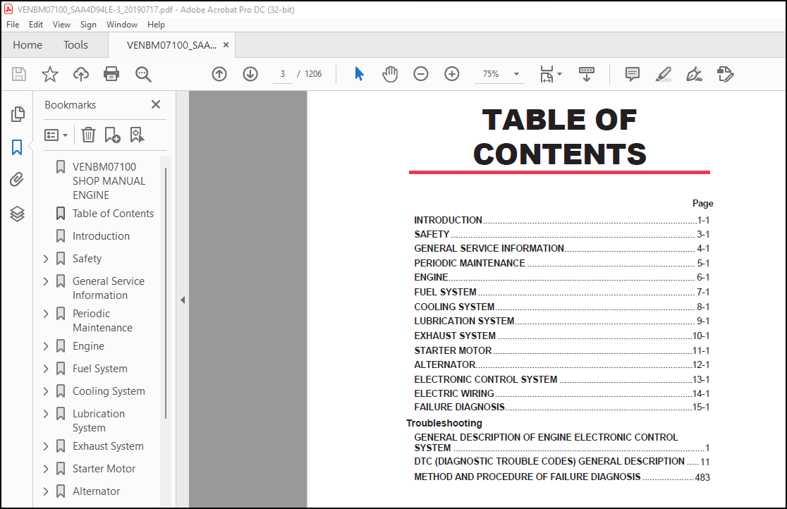
TABLE OF CONTENTS:
Komatsu SAA4D94LE-3 Engine Shop Manual VENBM07100 – PDF DOWNLOAD
VENBM07100 SHOP MANUAL ENGINE…………………………………………………………………………………………………………………… 1
Table of Contents……………………………………………………………………………………………………………………………… 3
Introduction………………………………………………………………………………………………………………………………….. 5
Safety……………………………………………………………………………………………………………………………………….. 7
Safety Statements………………………………………………………………………………………………………………………….. 9
Safety Precautions…………………………………………………………………………………………………………………………. 10
General Service Information…………………………………………………………………………………………………………………….. 23
Component Identification……………………………………………………………………………………………………………………. 25
Location of Labels…………………………………………………………………………………………………………………………. 26
Location of labels/nameplates on direct injection model engines……………………………………………………………………………… 26
Engine Nameplate (Typical)………………………………………………………………………………………………………………. 26
Emission Control Regulations………………………………………………………………………………………………………………… 26
EPA/ARB Regulations – USA Only…………………………………………………………………………………………………………… 26
Emission Control Labels…………………………………………………………………………………………………………………….. 26
EPA/ARB labels (Typical)………………………………………………………………………………………………………………… 26
EPA……………………………………………………………………………………………………………………………….. 26
EPA and ARB………………………………………………………………………………………………………………………… 26
The 97/68/EC Directive Certified Labels…………………………………………………………………………………………………… 27
ENGINE FAMILY……………………………………………………………………………………………………………………………… 27
Function of Major Engine Components………………………………………………………………………………………………………….. 28
Function of Cooling System Components………………………………………………………………………………………………………… 29
Main Electronic Control Components and Features……………………………………………………………………………………………….. 30
Installation Position of Sensors…………………………………………………………………………………………………………….. 32
Crank rotation sensor…………………………………………………………………………………………………………………… 33
Cam speed sensor……………………………………………………………………………………………………………………….. 33
New air temperature sensor………………………………………………………………………………………………………………. 34
EGR gas temperature sensor………………………………………………………………………………………………………………. 34
Intake air temperature sensor……………………………………………………………………………………………………………. 34
Fuel temperature sensor (equipped on supply pump)………………………………………………………………………………………….. 35
Engine coolant temperature sensor………………………………………………………………………………………………………… 35
Exhaust temperature sensor………………………………………………………………………………………………………………. 36
Diesel Particulate Filter (DPF) inlet/inside temperature sensor……………………………………………………………………………… 36
SCR temperature sensor………………………………………………………………………………………………………………….. 36
Rail pressure sensor……………………………………………………………………………………………………………………. 36
EGR pressure sensor…………………………………………………………………………………………………………………….. 37
Diesel Particulate Filter (DPF) exhaust differential pressure sensor…………………………………………………………………………. 38
NOx sensor…………………………………………………………………………………………………………………………….. 39
Intake air throttles……………………………………………………………………………………………………………………. 41
Acceleration sensor (YANMAR standard)…………………………………………………………………………………………………….. 42
Diesel Fuel……………………………………………………………………………………………………………………………….. 43
Diesel Fuel Specifications………………………………………………………………………………………………………………. 43
Additional technical fuel requirements………………………………………………………………………………………………… 43
Precautions and concerns regarding the use of diesel fuel……………………………………………………………………………….. 43
Biodiesel fuels…………………………………………………………………………………………………………………….. 43
Kit component for B20 (4TNV94FHT)…………………………………………………………………………………………………….. 46
Filling The Fuel Tank…………………………………………………………………………………………………………………… 47
Priming the Fuel System…………………………………………………………………………………………………………………. 48
Engine Oil………………………………………………………………………………………………………………………………… 49
Engine Oil Specifications……………………………………………………………………………………………………………….. 49
Service categories………………………………………………………………………………………………………………….. 49
Definitions………………………………………………………………………………………………………………………… 49
Additional technical engine oil requirements:………………………………………………………………………………………….. 49
Engine Oil Viscosity……………………………………………………………………………………………………………………. 49
Checking Engine Oil…………………………………………………………………………………………………………………….. 50
Adding Engine Oil………………………………………………………………………………………………………………………. 50
Engine Oil Capacity (Typical)……………………………………………………………………………………………………………. 50
Engine Coolant…………………………………………………………………………………………………………………………….. 51
Engine Coolant Specifications……………………………………………………………………………………………………………. 51
Alternative engine coolant…………………………………………………………………………………………………………… 51
Filling Radiator with Engine Coolant……………………………………………………………………………………………………… 52
Daily Check of the Cooling System………………………………………………………………………………………………………… 52
Engine Coolant Capacity (Typical)………………………………………………………………………………………………………… 52
Aqueous urea………………………………………………………………………………………………………………………………. 53
Aqueous Urea Solution Standard…………………………………………………………………………………………………………… 53
Property and Characteristics of Aqueous Urea………………………………………………………………………………………………. 53
Prohibition……………………………………………………………………………………………………………………………. 53
Precaution…………………………………………………………………………………………………………………………….. 54
Storing the Aqueous Urea………………………………………………………………………………………………………………… 54
Refilling Aqueous Urea………………………………………………………………………………………………………………….. 54
Specifications…………………………………………………………………………………………………………………………….. 55
Description of Model Number……………………………………………………………………………………………………………… 55
Engine General Specifications……………………………………………………………………………………………………………. 55
Principal Engine Specifications……………………………………………………………………………………………………………… 56
4TNV94FHT (EPA Final Tier 4)…………………………………………………………………………………………………………….. 56
Engine Service Standards……………………………………………………………………………………………………………………. 57
Tightening Torques for Standard Bolts and Nuts………………………………………………………………………………………………… 58
Abbreviations and Symbols…………………………………………………………………………………………………………………… 60
Abbreviations………………………………………………………………………………………………………………………….. 60
Symbols……………………………………………………………………………………………………………………………….. 60
Unit Conversions…………………………………………………………………………………………………………………………… 61
Unit prefixes………………………………………………………………………………………………………………………….. 61
Units of length………………………………………………………………………………………………………………………… 61
Units of volume………………………………………………………………………………………………………………………… 61
Units of mass………………………………………………………………………………………………………………………….. 61
Units of force…………………………………………………………………………………………………………………………. 61
Units of torque………………………………………………………………………………………………………………………… 61
Units of pressure………………………………………………………………………………………………………………………. 61
Units of power…………………………………………………………………………………………………………………………. 61
Units of temperature……………………………………………………………………………………………………………………. 61
Periodic Maintenance…………………………………………………………………………………………………………………………… 63
Before You Begin Servicing………………………………………………………………………………………………………………….. 65
Introduction………………………………………………………………………………………………………………………………. 66
The Importance of Periodic Maintenance……………………………………………………………………………………………………. 66
Performing Periodic Maintenance………………………………………………………………………………………………………….. 66
YANMAR Replacement Parts………………………………………………………………………………………………………………… 66
Required EPA/ARB Maintenance – USA Only…………………………………………………………………………………………………… 66
EPA/ARB Installation Requirements – USA Only………………………………………………………………………………………………. 66
Periodic Maintenance Schedule……………………………………………………………………………………………………………….. 67
Periodic Maintenance Procedures……………………………………………………………………………………………………………… 69
After Initial 50 Hours of Operation………………………………………………………………………………………………………. 69
Check and adjust cooling fan V-belt…………………………………………………………………………………………………… 69
Every 50 Hours of Operation……………………………………………………………………………………………………………… 70
Drain water separator……………………………………………………………………………………………………………….. 70
Check battery………………………………………………………………………………………………………………………. 72
Every 250 Hours of Operation…………………………………………………………………………………………………………….. 73
Drain fuel tank…………………………………………………………………………………………………………………….. 73
Check and clean radiator fins………………………………………………………………………………………………………… 74
Check and adjust cooling fan V-belt…………………………………………………………………………………………………… 74
Clean air cleaner element……………………………………………………………………………………………………………. 74
Every 500 Hours of Operation…………………………………………………………………………………………………………….. 75
Replace air cleaner element………………………………………………………………………………………………………….. 75
Replace fuel filter…………………………………………………………………………………………………………………. 76
Replace water separator element………………………………………………………………………………………………………. 77
Replace engine oil and engine oil filter………………………………………………………………………………………………. 78
Every 1000 Hours of Operation……………………………………………………………………………………………………………. 80
Check and adjust intake/exhaust valve clearance………………………………………………………………………………………… 80
Every 1500 Hours of Operation……………………………………………………………………………………………………………. 81
Inspect crankcase breather system…………………………………………………………………………………………………….. 81
Every 2000 Hours of Operation……………………………………………………………………………………………………………. 82
Check and replace fuel hoses, engine coolant hoses and engine lubricating oil hoses………………………………………………………… 82
Lap the intake and exhaust valves…………………………………………………………………………………………………….. 82
Replace engine coolant………………………………………………………………………………………………………………. 82
Every 3000 Hours of Operation……………………………………………………………………………………………………………. 84
Inspect ECU and related sensors and actuators………………………………………………………………………………………….. 84
Inspect turbocharger (blower cleaning if necessary)…………………………………………………………………………………….. 84
Cleaning the EGR cooler (water side/exhaust passage)……………………………………………………………………………………. 84
Inspect DPF DOC…………………………………………………………………………………………………………………….. 84
Inspect and test intake throttle valve………………………………………………………………………………………………… 85
Inspect SCR catalyst and related sensors and actuators………………………………………………………………………………….. 85
Check and replace SM (Supply Module) main filter……………………………………………………………………………………….. 85
Check and clean injector…………………………………………………………………………………………………………….. 85
Every 6000 Hours of Operation……………………………………………………………………………………………………………. 85
Check and clean of DPF soot filter……………………………………………………………………………………………………. 85
Engine……………………………………………………………………………………………………………………………………….. 87
Before You Begin Servicing………………………………………………………………………………………………………………….. 89
Introduction………………………………………………………………………………………………………………………………. 90
Cylinder Head Specifications………………………………………………………………………………………………………………… 90
Adjustment Specifications……………………………………………………………………………………………………………….. 90
Cylinder Head………………………………………………………………………………………………………………………….. 90
Intake/Exhaust Valve and Guide…………………………………………………………………………………………………………… 90
Push Rod………………………………………………………………………………………………………………………………. 91
Rocker Arm and Shaft……………………………………………………………………………………………………………………. 91
Valve Spring…………………………………………………………………………………………………………………………… 91
Valve Bridge…………………………………………………………………………………………………………………………… 91
Camshaft and Timing Gear Train Specifications…………………………………………………………………………………………………. 92
Camshaft………………………………………………………………………………………………………………………………. 92
Idler Gear Shaft and Bushing…………………………………………………………………………………………………………….. 92
Timing Gear Backlash……………………………………………………………………………………………………………………. 92
Crankshaft and Piston Specifications…………………………………………………………………………………………………………. 93
Crankshaft…………………………………………………………………………………………………………………………….. 93
Thrust Bearing…………………………………………………………………………………………………………………………. 93
Piston………………………………………………………………………………………………………………………………… 93
Piston Ring……………………………………………………………………………………………………………………………. 94
Connecting Rod…………………………………………………………………………………………………………………………. 94
Connecting rod small end…………………………………………………………………………………………………………….. 94
Connecting rod big end………………………………………………………………………………………………………………. 94
Tappet………………………………………………………………………………………………………………………………… 95
Cylinder Block Specifications……………………………………………………………………………………………………………….. 95
Cylinder Block…………………………………………………………………………………………………………………………. 95
Special Torque Chart……………………………………………………………………………………………………………………….. 96
Torque for Bolts and Nuts……………………………………………………………………………………………………………….. 96
Special Service Tools………………………………………………………………………………………………………………………. 97
Measuring Instruments………………………………………………………………………………………………………………………. 100
Cylinder Head……………………………………………………………………………………………………………………………… 102
Cylinder Head Components………………………………………………………………………………………………………………… 102
Disassembly of Cylinder Head…………………………………………………………………………………………………………….. 103
Removal of rocker arm assembly……………………………………………………………………………………………………….. 111
Disassembly of rocker arm assembly……………………………………………………………………………………………………. 111
Removal of cylinder head…………………………………………………………………………………………………………….. 112
Removal of intake and exhaust valves………………………………………………………………………………………………….. 112
Removal of valve guides……………………………………………………………………………………………………………… 113
Cleaning of Cylinder Head Components……………………………………………………………………………………………………… 113
Inspection of Cylinder Head Components……………………………………………………………………………………………………. 113
Inspection of push rods……………………………………………………………………………………………………………… 113
Inspection of rocker arm assembly…………………………………………………………………………………………………….. 114
Inspection of valve guides…………………………………………………………………………………………………………… 114
Inspection of cylinder head………………………………………………………………………………………………………….. 114
Inspection of intake and exhaust valves……………………………………………………………………………………………….. 115
Inspection of valve springs………………………………………………………………………………………………………….. 117
Inspection of valve bridges………………………………………………………………………………………………………….. 117
Reassembly of Cylinder Head……………………………………………………………………………………………………………… 117
Reassembly of valve guides…………………………………………………………………………………………………………… 118
Reassembly of intake and exhaust valves……………………………………………………………………………………………….. 118
Reassembly of cylinder head………………………………………………………………………………………………………….. 119
Reassembly of rocker arm assembly…………………………………………………………………………………………………….. 120
Reassembly of surrounding parts of cylinder heads………………………………………………………………………………………. 121
Measuring and Adjusting Valve Clearance………………………………………………………………………………………………………. 124
4-cylinder engines……………………………………………………………………………………………………………………… 124
4-Valve Cylinder Heads………………………………………………………………………………………………………………….. 125
Crankshaft and Camshaft Components…………………………………………………………………………………………………………… 127
Disassembly of Engine…………………………………………………………………………………………………………………… 128
Disassembly of Camshaft and Timing Components……………………………………………………………………………………………… 129
Removal of timing gear case cover…………………………………………………………………………………………………….. 129
Checking timing gear backlash………………………………………………………………………………………………………… 129
Measuring idler gear-to-crankshaft gear backlash……………………………………………………………………………………….. 129
Measuring idler gear-to-camshaft gear backlash…………………………………………………………………………………………. 130
Removal of timing gears……………………………………………………………………………………………………………… 130
Removal of oil pan………………………………………………………………………………………………………………….. 130
Removal of camshaft…………………………………………………………………………………………………………………. 131
Removal of gear case………………………………………………………………………………………………………………… 132
Disassembly of Crankshaft and Piston Components……………………………………………………………………………………………. 132
Removal of pistons………………………………………………………………………………………………………………….. 132
Removal of crankshaft……………………………………………………………………………………………………………….. 134
Inspection of Crankshaft and Camshaft Components…………………………………………………………………………………………… 135
Replacement of crankshaft oil seals…………………………………………………………………………………………………… 136
Measure crankshaft bearing oil clearance………………………………………………………………………………………………. 136
Inspection of cylinder block…………………………………………………………………………………………………………. 136
Inspection of pistons, piston rings and wrist pin………………………………………………………………………………………. 136
Inspection of connecting rod…………………………………………………………………………………………………………. 138
Inspection of tappets……………………………………………………………………………………………………………….. 139
Inspection of crankshaft…………………………………………………………………………………………………………….. 139
Inspection of camshaft………………………………………………………………………………………………………………. 140
Inspection of camshaft bushing and bores………………………………………………………………………………………………. 141
Inspection of idler gear and shaft……………………………………………………………………………………………………. 141
Honing and Boring………………………………………………………………………………………………………………………. 141
Reassembly of Crankshaft and Piston Components…………………………………………………………………………………………….. 142
Reassembly of pistons……………………………………………………………………………………………………………….. 143
Installation of crankshaft…………………………………………………………………………………………………………… 145
Installation of pistons……………………………………………………………………………………………………………… 146
Reassembly of Camshaft and Timing Components………………………………………………………………………………………………. 148
Installation of gear case……………………………………………………………………………………………………………. 148
Installation of camshaft…………………………………………………………………………………………………………….. 148
Installation of timing gears…………………………………………………………………………………………………………. 149
Installation of gear case cover………………………………………………………………………………………………………. 149
Installation of oil pan……………………………………………………………………………………………………………… 150
Final Reassembly of Engine………………………………………………………………………………………………………………. 150
Fuel System…………………………………………………………………………………………………………………………………… 151
Before You Begin Servicing………………………………………………………………………………………………………………….. 153
System Structure…………………………………………………………………………………………………………………………… 154
Supply pump……………………………………………………………………………………………………………………………. 154
Rail………………………………………………………………………………………………………………………………….. 154
Injector………………………………………………………………………………………………………………………………. 154
Crank speed sensor and cam speed sensor…………………………………………………………………………………………………… 155
ECU…………………………………………………………………………………………………………………………………… 155
Fuel System Specifications………………………………………………………………………………………………………………….. 156
Torque Chart for Major Bolts and Nuts…………………………………………………………………………………………………….. 156
General Torque Chart (Lubrication Oil not Applied)…………………………………………………………………………………………. 157
Fuel System Diagram………………………………………………………………………………………………………………………… 158
Fuel System Components……………………………………………………………………………………………………………………… 159
Common Rail……………………………………………………………………………………………………………………………. 160
Pressure limiter replacement procedures……………………………………………………………………………………………….. 160
Pressure sensor replacement procedures………………………………………………………………………………………………… 162
Common rail replacement procedures……………………………………………………………………………………………………. 164
Injector………………………………………………………………………………………………………………………………. 166
Injector replacement procedures………………………………………………………………………………………………………. 166
Supply Pump……………………………………………………………………………………………………………………………. 169
SCV replacement procedures…………………………………………………………………………………………………………… 169
Hollow screw replacement procedures…………………………………………………………………………………………………… 172
Fuel temperature sensor replacement procedures…………………………………………………………………………………………. 174
Supply pump replacement procedures……………………………………………………………………………………………………. 176
Cooling System………………………………………………………………………………………………………………………………… 181
Before You Begin Servicing………………………………………………………………………………………………………………….. 183
Cooling System Diagram……………………………………………………………………………………………………………………… 184
Engine Coolant Pump Components………………………………………………………………………………………………………………. 185
Engine Coolant System Check…………………………………………………………………………………………………………………. 186
Engine Coolant Pump………………………………………………………………………………………………………………………… 186
Removal of Engine Coolant Pump…………………………………………………………………………………………………………… 186
Disassembly of Engine Coolant Pump……………………………………………………………………………………………………….. 187
Cleaning and Inspection…………………………………………………………………………………………………………………. 188
Engine coolant temperature sensor…………………………………………………………………………………………………….. 188
Thermostat…………………………………………………………………………………………………………………………. 188
Radiator cap……………………………………………………………………………………………………………………….. 188
Reassembly of Engine Coolant Pump………………………………………………………………………………………………………… 189
Installation of Engine Coolant Pump………………………………………………………………………………………………………. 189
Lubrication System…………………………………………………………………………………………………………………………….. 191
Before You Begin Servicing………………………………………………………………………………………………………………….. 193
Introduction………………………………………………………………………………………………………………………………. 193
Oil Pump Service Information………………………………………………………………………………………………………………… 194
Engine oil pressure…………………………………………………………………………………………………………………….. 194
Outer rotor outside clearance……………………………………………………………………………………………………………. 194
Outer rotor side clearance………………………………………………………………………………………………………………. 194
Outer rotor to inner rotor tip clearance………………………………………………………………………………………………….. 194
Rotor shaft clearance…………………………………………………………………………………………………………………… 194
Lubrication System Diagram………………………………………………………………………………………………………………….. 195
Checking Engine Oil Pressure………………………………………………………………………………………………………………… 196
Trochoid Oil Pump………………………………………………………………………………………………………………………….. 196
Oil Pump Components…………………………………………………………………………………………………………………….. 196
Disassembly of Oil Pump…………………………………………………………………………………………………………………. 197
Cleaning and Inspection…………………………………………………………………………………………………………………. 197
Check outer rotor outside clearance…………………………………………………………………………………………………… 197
Outer rotor to inner rotor tip clearance………………………………………………………………………………………………. 198
Check outer rotor side clearance……………………………………………………………………………………………………… 198
Check rotor shaft clearance………………………………………………………………………………………………………….. 198
Reassembly of Oil Pump………………………………………………………………………………………………………………….. 198
Exhaust System………………………………………………………………………………………………………………………………… 201
EGR System………………………………………………………………………………………………………………………………… 203
EGR System Configuration………………………………………………………………………………………………………………… 203
EGR valve………………………………………………………………………………………………………………………….. 204
EGR lead valve……………………………………………………………………………………………………………………… 204
EGR cooler…………………………………………………………………………………………………………………………. 204
Disassembly of EGR System……………………………………………………………………………………………………………….. 204
EGR cooler…………………………………………………………………………………………………………………………. 205
EGR valve/Lead valve………………………………………………………………………………………………………………… 205
Cleaning the EGR Cooler (Water Side/Exhaust Passage Blower)…………………………………………………………………………………. 206
Cleaning the EGR Pipe and Other Connecting Elbows………………………………………………………………………………………….. 206
Check, Clean, and Test EGR Valve…………………………………………………………………………………………………………. 206
EGR active control………………………………………………………………………………………………………………….. 207
Cleaning the EGR valves……………………………………………………………………………………………………………… 208
Exit the EGR active control………………………………………………………………………………………………………….. 209
Precautions for cleaning…………………………………………………………………………………………………………….. 209
Cleaning the EGR Lead Valves…………………………………………………………………………………………………………….. 209
Precautions for installation…………………………………………………………………………………………………………. 209
Assembling around the EGR Valve………………………………………………………………………………………………………….. 209
Intake Throttle………………………………………………………………………………………………………………………… 210
Precautions for handling the intake throttle…………………………………………………………………………………………… 210
Turbocharger………………………………………………………………………………………………………………………………. 211
Before You Begin Servicing………………………………………………………………………………………………………………. 211
Introduction…………………………………………………………………………………………………………………………… 211
Specifications…………………………………………………………………………………………………………………………. 211
Turbocharger service information……………………………………………………………………………………………………… 211
Structure of turbocharger……………………………………………………………………………………………………………. 213
Role of waste gate………………………………………………………………………………………………………………….. 214
Periodic Inspection…………………………………………………………………………………………………………………….. 215
Visual inspection…………………………………………………………………………………………………………………… 215
Inspection of rotor rotation…………………………………………………………………………………………………………. 215
Checking the rotor play……………………………………………………………………………………………………………… 215
Checking the waste gate valve………………………………………………………………………………………………………… 216
Removal and Installation of turbocharger………………………………………………………………………………………………….. 217
Removal of turbocharger……………………………………………………………………………………………………………… 217
Installation of turbocharger…………………………………………………………………………………………………………. 217
Cleaning Procedure……………………………………………………………………………………………………………………… 218
Excessive exhaust smoke……………………………………………………………………………………………………………… 219
Sudden oil decrease…………………………………………………………………………………………………………………. 220
Decrease in output………………………………………………………………………………………………………………….. 220
Poor (slow) response (starting) of turbocharger………………………………………………………………………………………… 220
Abnormal sound or vibration………………………………………………………………………………………………………….. 220
Diesel Particulate Filter (DPF)……………………………………………………………………………………………………………… 221
Outline of Diesel Particulate Filter (DPF)………………………………………………………………………………………………… 221
Overview of Diesel Particulate Filter (DPF) Regeneration Control…………………………………………………………………………….. 222
Self-Regeneration………………………………………………………………………………………………………………………. 222
Assisted Regeneration…………………………………………………………………………………………………………………… 222
Reset Regeneration……………………………………………………………………………………………………………………… 222
Stationary Regeneration…………………………………………………………………………………………………………………. 222
Operation Procedures of Stationary Regeneration……………………………………………………………………………………………. 223
Precautions for Stationary Regeneration…………………………………………………………………………………………………… 223
Recovery Regeneration (Optional)…………………………………………………………………………………………………………. 223
Precautions for Recovery Regeneration…………………………………………………………………………………………………….. 223
Urea SCR System……………………………………………………………………………………………………………………………. 224
Description……………………………………………………………………………………………………………………………. 224
System Structure……………………………………………………………………………………………………………………….. 224
Description of SCR……………………………………………………………………………………………………………………… 225
Device of Urea SCR System……………………………………………………………………………………………………………….. 226
SCR……………………………………………………………………………………………………………………………….. 226
SM (Supply Module)………………………………………………………………………………………………………………….. 227
DM (Dosing Module)………………………………………………………………………………………………………………….. 227
DCU (Dosing Control Unit)……………………………………………………………………………………………………………. 228
Aqueous urea hose…………………………………………………………………………………………………………………… 230
Maintenance service for After Treatment Device………………………………………………………………………………………………… 231
Service Period…………………………………………………………………………………………………………………………. 231
Replacing and Cleaning………………………………………………………………………………………………………………….. 232
Replacing the DPF or SCR…………………………………………………………………………………………………………….. 232
Cleaning the SF…………………………………………………………………………………………………………………….. 237
Replacing the ATD unit………………………………………………………………………………………………………………. 238
Urea SCR System Maintenance…………………………………………………………………………………………………………………. 239
Checking and Replacing the SM (Supply Module) Main Filter…………………………………………………………………………………… 239
Replacing the main filter……………………………………………………………………………………………………………. 239
Caution on replacing the filter cover…………………………………………………………………………………………………. 241
Replacing procedure of the Supply Module………………………………………………………………………………………………. 241
Inspection of the DM (Dosing Module) and Replacing the Sealing Plate…………………………………………………………………………. 242
Replacing procedure for DM sealing plate………………………………………………………………………………………………. 242
Starter Motor…………………………………………………………………………………………………………………………………. 245
Before You Begin Servicing………………………………………………………………………………………………………………….. 247
Introduction………………………………………………………………………………………………………………………………. 247
Starter Motor Information…………………………………………………………………………………………………………………… 248
Starter Motor Specifications………………………………………………………………………………………………………………… 248
Starter Motor Troubleshooting……………………………………………………………………………………………………………….. 249
Starter Motor Components……………………………………………………………………………………………………………………. 250
Starter Motor……………………………………………………………………………………………………………………………… 251
Removal of Starter Motor………………………………………………………………………………………………………………… 251
Disassembly of Starter Motor…………………………………………………………………………………………………………….. 251
Cleaning and Inspection…………………………………………………………………………………………………………………. 253
Armature…………………………………………………………………………………………………………………………… 253
Field coil…………………………………………………………………………………………………………………………. 255
Magnetic switch…………………………………………………………………………………………………………………….. 255
Pinion clutch assembly………………………………………………………………………………………………………………. 256
Reassembly of Starter Motor……………………………………………………………………………………………………………… 257
Check Pinion Projection Length…………………………………………………………………………………………………………… 258
No-Load Test…………………………………………………………………………………………………………………………… 259
Installation of Starter Motor……………………………………………………………………………………………………………. 260
Alternator……………………………………………………………………………………………………………………………………. 261
Before You Begin Servicing………………………………………………………………………………………………………………….. 263
Introduction………………………………………………………………………………………………………………………………. 263
Alternator Specifications…………………………………………………………………………………………………………………… 264
Alternator Troubleshooting………………………………………………………………………………………………………………….. 265
Alternator Components………………………………………………………………………………………………………………………. 266
Alternator Wiring Diagram…………………………………………………………………………………………………………………… 267
Alternator Standard Output………………………………………………………………………………………………………………….. 268
Alternator………………………………………………………………………………………………………………………………… 269
Removal of Alternator…………………………………………………………………………………………………………………… 269
Disassembly of Alternator……………………………………………………………………………………………………………….. 269
Reassembly of Alternator………………………………………………………………………………………………………………… 271
Installation of Alternator………………………………………………………………………………………………………………. 273
Electronic Control System………………………………………………………………………………………………………………………. 275
Before You Begin Servicing………………………………………………………………………………………………………………….. 277
Introduction………………………………………………………………………………………………………………………………. 277
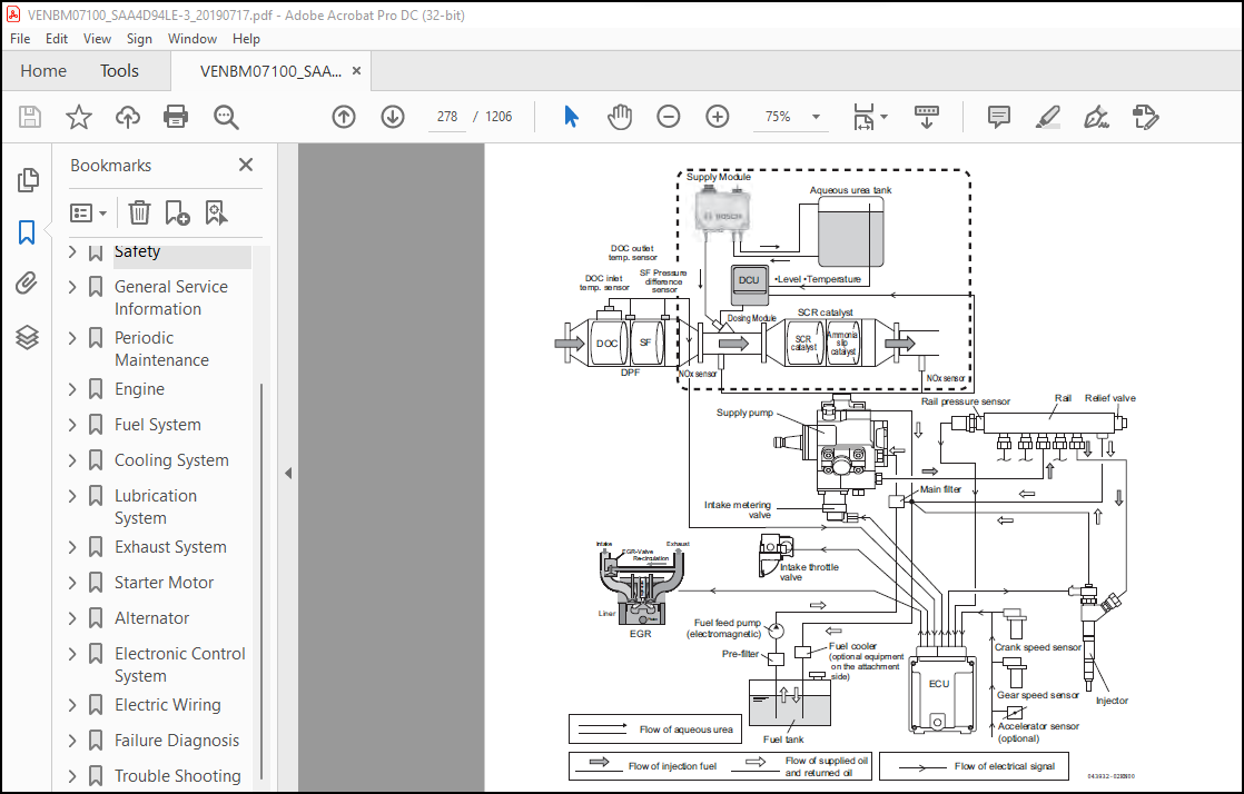
Electronic Control System…………………………………………………………………………………………………………………… 278
Troubleshooting of Electronic Control System………………………………………………………………………………………………….. 279
Fault detection capability………………………………………………………………………………………………………………. 279
SMARTASSIST-DIRECT (SA-D)……………………………………………………………………………………………………………….. 280
About SA-D use……………………………………………………………………………………………………………………… 281
Replacement of Components…………………………………………………………………………………………………………………… 282
Processing the DPF regeneration after the parts replacement…………………………………………………………………………………. 282
Processing after the ECU replacement (when it is impossible to inherit from the old ECU)……………………………………………………….. 283
Required processing at the CR-related parts replacement…………………………………………………………………………………….. 284
Electronic Control Harness Connections……………………………………………………………………………………………………….. 286
Electric Wiring……………………………………………………………………………………………………………………………….. 299
Electric Wiring Precautions…………………………………………………………………………………………………………………. 301
Electrical Wire Resistance………………………………………………………………………………………………………………….. 302
Battery Cable Resistance……………………………………………………………………………………………………………………. 303
Electrical Wire Sizes – Voltage Drop…………………………………………………………………………………………………………. 304
Conversion of AWG to European Standards………………………………………………………………………………………………………. 305
Failure Diagnosis……………………………………………………………………………………………………………………………… 307
Special Service Tools………………………………………………………………………………………………………………………. 309
Troubleshooting by Measuring Compression Pressure……………………………………………………………………………………………… 310
Compression pressure inspection procedures………………………………………………………………………………………………… 310
Injector reassembly procedures…………………………………………………………………………………………………………… 311
Engine speed and compression pressure (use for reference)…………………………………………………………………………………… 312
Measured Value and Troubleshooting…………………………………………………………………………………………………………… 313
Quick Reference Table for Troubleshooting…………………………………………………………………………………………………….. 314
Failure Diagnostic List…………………………………………………………………………………………………………………. 315
Trouble Shooting………………………………………………………………………………………………………………………………. 319
CONTENTS………………………………………………………………………………………………………………………………….. 321
GENERAL DESCRIPTION OF ENGINE ELECTRONIC CONTROL SYSTEM………………………………………………………………………………………… 333
System Configuration of Engine Electronic Control System……………………………………………………………………………………. 333
Engine ECU and DCU After-run Time………………………………………………………………………………………………………… 337
Output Limit by Inducement at SCR System Error…………………………………………………………………………………………….. 338
Output Limit by Inducement when Aqueous Urea Tank Level is Low………………………………………………………………………………. 340
SCR System Limited Operation…………………………………………………………………………………………………………….. 341
DTC (DIAGNOSTIC TROUBLE CODES) GENERAL DESCRIPTION…………………………………………………………………………………………….. 343
DTC Code List………………………………………………………………………………………………………………………….. 343
Engine ECU judgment item…………………………………………………………………………………………………………….. 343
DCU judgment item…………………………………………………………………………………………………………………… 347
Description……………………………………………………………………………………………………………………………. 351
Engine ECU Judgment Item………………………………………………………………………………………………………………… 352
Sensor related……………………………………………………………………………………………………………………… 352
Crankshaft speed sensor………………………………………………………………………………………………………….. 352
P0336: Crankshaft signal error………………………………………………………………………………………………… 352
P0337: No signal from crankshaft………………………………………………………………………………………………. 354
Camshaft speed sensor……………………………………………………………………………………………………………. 356
P0341: Camshaft signal error………………………………………………………………………………………………….. 356
P0342: No signal from camshaft………………………………………………………………………………………………… 358
Crankshaft speed sensor/camshaft speed sensor………………………………………………………………………………………. 360
P0008: Crankshaft/camshaft speed sensor non-input (simultaneous)………………………………………………………………….. 360
Accelerator sensor 1…………………………………………………………………………………………………………….. 362
P0123: Accelerator sensor 1 error (voltage high)………………………………………………………………………………… 362
P0122: Accelerator sensor 1 error (voltage low)…………………………………………………………………………………. 364
Accelerator sensor 3…………………………………………………………………………………………………………….. 366
P0228: Accelerator sensor 3 error (voltage high)………………………………………………………………………………… 366
P0227: Accelerator sensor 3 error (voltage low)…………………………………………………………………………………. 368
P1126: Accelerator sensor 3 error (foot pedal in open position)…………………………………………………………………… 370
P1125: Accelerator sensor 3 error (foot pedal in closed position)…………………………………………………………………. 372
Intake throttle position sensor…………………………………………………………………………………………………… 374
P02E9: Intake throttle position sensor error (voltage high)………………………………………………………………………. 374
P02E8: Intake throttle position sensor error (voltage low)……………………………………………………………………….. 376
EGR low pressure side pressure sensor……………………………………………………………………………………………… 378
P0238: EGR low pressure side pressure sensor error (voltage high)…………………………………………………………………. 378
P0237: EGR low pressure side pressure sensor error (voltage low)………………………………………………………………….. 380
P0236: EGR low pressure side pressure sensor error (abnormal learning value)……………………………………………………….. 382
P1673: EGR low pressure side pressure sensor error (detected value error)………………………………………………………….. 384
EGR high pressure side pressure sensor…………………………………………………………………………………………….. 386
P0473: EGR high pressure side pressure sensor error (voltage high)………………………………………………………………… 386
P0472: EGR high pressure side pressure sensor error (voltage low)…………………………………………………………………. 388
P0471: EGR high pressure side pressure sensor error (abnormal learning value)………………………………………………………. 390
P1679: EGR high pressure side pressure sensor error (detected value error)…………………………………………………………. 392
Engine coolant temperature sensor…………………………………………………………………………………………………. 394
P0118: Engine coolant temperature sensor error (voltage high)…………………………………………………………………….. 394
P0117: Engine coolant temperature sensor error (voltage low)……………………………………………………………………… 396
P0217: Engine coolant temperature high (overheat)……………………………………………………………………………….. 398
P1674: Engine coolant temperature sensor error (detected value error)……………………………………………………………… 400
Ambient air temperature sensor……………………………………………………………………………………………………. 402
P0113: Ambient air temperature sensor error (voltage high)……………………………………………………………………….. 402
P0112: Ambient air temperature sensor error (voltage low)………………………………………………………………………… 404
P1678: Ambient air temperature sensor error (detected value error)………………………………………………………………… 406
Fuel temperature sensor………………………………………………………………………………………………………….. 408
P0183: Fuel temperature sensor error (voltage high)……………………………………………………………………………… 408
P0182: Fuel temperature sensor error (voltage low)………………………………………………………………………………. 410
P0168: Fuel temperature high………………………………………………………………………………………………….. 412
Rail pressure sensor…………………………………………………………………………………………………………….. 414
P0193: Rail pressure sensor error (voltage high)………………………………………………………………………………… 414
P0192: Rail pressure sensor error (voltage low)…………………………………………………………………………………. 416
DPF differential pressure sensor………………………………………………………………………………………………….. 418
P2455: DPF differential pressure sensor error (voltage high)……………………………………………………………………… 418
P2454: DPF differential pressure sensor error (voltage low)………………………………………………………………………. 420
P2453: DPF differential pressure sensor error (abnormal learning value)……………………………………………………………. 422
P2452: DPF differential pressure sensor abnormal rise in differential pressure……………………………………………………… 424
DPF substrate/DPF differential pressure sensor……………………………………………………………………………………… 425
P226D: DPF substrate/DPF differential pressure sensor error (DPF substrate removal/DPF differential pressure sensor detected value error)…. 425
DPF high pressure side pressure sensor…………………………………………………………………………………………….. 427
P1455: DPF high pressure side pressure sensor error (detected value error)…………………………………………………………. 427
P1454: DPF high pressure side pressure sensor error (voltage low)…………………………………………………………………. 429
DPF inlet temperature sensor……………………………………………………………………………………………………… 433
P1428: DPF inlet temperature sensor error (voltage high)…………………………………………………………………………. 433
P1427: DPF inlet temperature sensor error (voltage low)………………………………………………………………………….. 435
P167E: DPF inlet temperature sensor error (detected value error)………………………………………………………………….. 437
P1436: DPF inlet temperature sensor abnormal temperature (abnormally high)…………………………………………………………. 439
DPF intermediate temperature sensor……………………………………………………………………………………………….. 440
P1434: DPF intermediate temperature sensor error (voltage high)…………………………………………………………………… 440
P1435: DPF intermediate temperature sensor error (voltage low)……………………………………………………………………. 442
P167A: DPF intermediate temperature sensor error (detected value error)……………………………………………………………. 444
P0420: DPF intermediate temperature sensor abnormal temperature (abnormally low)……………………………………………………. 446
P1426: DPF intermediate temperature sensor abnormal rise in temperature (post-injection malfunction)………………………………….. 447
Atmospheric pressure sensor………………………………………………………………………………………………………. 448
P2229: Atmospheric pressure sensor error (voltage high)………………………………………………………………………….. 448
P2228: Atmospheric pressure sensor error (voltage low)…………………………………………………………………………… 449
P1231: Atmospheric pressure sensor error (characteristic error)…………………………………………………………………… 450
EGR gas temperature sensor……………………………………………………………………………………………………….. 451
P041D: EGR gas temperature sensor error (voltage high)…………………………………………………………………………… 451
P041C: EGR gas temperature sensor error (voltage low)……………………………………………………………………………. 453
P1675: EGR gas temperature sensor error (detected value error)……………………………………………………………………. 455
Intake manifold temperature sensor………………………………………………………………………………………………… 457
P040D: Intake manifold temperature sensor error (voltage high)……………………………………………………………………. 457
P040C: Intake manifold temperature sensor error (voltage low)…………………………………………………………………….. 459
P1676: Intake manifold temperature sensor error (detected value error)…………………………………………………………….. 461
Exhaust manifold temperature sensor……………………………………………………………………………………………….. 463
P0546: Exhaust manifold temperature sensor error (voltage high)…………………………………………………………………… 463
P0545: Exhaust manifold temperature sensor error (voltage low)……………………………………………………………………. 465
P1677: Exhaust manifold temperature sensor error (detected value error)……………………………………………………………. 467
Contact output related………………………………………………………………………………………………………………. 469
Main relay……………………………………………………………………………………………………………………… 469
P068A: Power off without main relay self-holding………………………………………………………………………………… 469
Starting aid relay………………………………………………………………………………………………………………. 470
P0543: Starting aid relay disconnection/VB short circuit…………………………………………………………………………. 470
P0541: Starting aid relay GND short circuit…………………………………………………………………………………….. 472
CRS (common rail system) related……………………………………………………………………………………………………… 474
Injector-specific……………………………………………………………………………………………………………….. 474
P0201: Injector (No. 1 cylinder) disconnection (injector-specific)………………………………………………………………… 474
P0202: Injector (No. 2 cylinder) disconnection (injector-specific)………………………………………………………………… 476
P0203: Injector (No. 3 cylinder) disconnection (injector-specific)………………………………………………………………… 478
P0204: Injector (No. 4 cylinder) disconnection (injector-specific)………………………………………………………………… 480
All injectors…………………………………………………………………………………………………………………… 482
P2148: Injector bank 1 + B short circuit……………………………………………………………………………………….. 482
P2147: Injector bank 1 GND short circuit……………………………………………………………………………………….. 484
P2146: Injector bank 1 disconnection…………………………………………………………………………………………… 486
P2151: Injector bank 2 + B short circuit……………………………………………………………………………………….. 488
P2150: Injector bank 2 GND short circuit……………………………………………………………………………………….. 490
P2149: Injector bank 2 disconnection…………………………………………………………………………………………… 492
Injector drive circuit…………………………………………………………………………………………………………… 494
P0611: Low charge error………………………………………………………………………………………………………. 494
P0200: Overcharge error………………………………………………………………………………………………………. 495
SCV (MPROP)…………………………………………………………………………………………………………………….. 496
P0629: SCV (MPROP) H/L side VB short circuit……………………………………………………………………………………. 496
P0627: SCV (MPROP) H side GND short circuit/disconnection………………………………………………………………………… 498
P2635: Drive circuit error (SCV sticking)………………………………………………………………………………………. 500
High pressure pump………………………………………………………………………………………………………………. 502
P1235: Pump protection failure………………………………………………………………………………………………… 502
P1236: Pump replacement failure……………………………………………………………………………………………….. 504
P1237: Pump learning not performed alarm……………………………………………………………………………………….. 506
Rail pressure error……………………………………………………………………………………………………………… 507
P0088: Rail pressure too high…………………………………………………………………………………………………. 507
P0094: Rail pressure deviation error (low rail pressure)…………………………………………………………………………. 508
Actuator…………………………………………………………………………………………………………………………… 509
Intake throttle drive circuit…………………………………………………………………………………………………….. 509
P0660: Intake throttle drive circuit disconnection………………………………………………………………………………. 509
P1658: Intake throttle drive circuit VB/GND short circuit………………………………………………………………………… 510
P1655: Intake throttle drive circuit deviation error…………………………………………………………………………….. 511
P1656: Intake throttle drive circuit drive duty error……………………………………………………………………………. 513
EGR……………………………………………………………………………………………………………………………. 515
P0403: Disconnection in EGR motor coils………………………………………………………………………………………… 515
P1405: EGR short circuit in motor coils………………………………………………………………………………………… 516
P0488: EGR position sensor error………………………………………………………………………………………………. 517
P1409: EGR feedback error…………………………………………………………………………………………………….. 518
P148A: EGR valve sticking error……………………………………………………………………………………………….. 519
P049D: EGR initialization error……………………………………………………………………………………………….. 520
U0401: EGR ECM data error…………………………………………………………………………………………………….. 521
U1401: EGR target value out of range…………………………………………………………………………………………… 522
P0404: EGR overvoltage error………………………………………………………………………………………………….. 523
P1404: EGR low voltage error………………………………………………………………………………………………….. 524
P1410: EGR high temperature thermistor error……………………………………………………………………………………. 525
P1411: EGR low temperature thermistor error…………………………………………………………………………………….. 526
Communication related……………………………………………………………………………………………………………….. 527
CAN……………………………………………………………………………………………………………………………. 527
U0292: TSC1 (SA1) reception timeout……………………………………………………………………………………………. 527
U1301: TSC1 (SA2) reception timeout……………………………………………………………………………………………. 528
U1292: Y_ECR1 reception timeout……………………………………………………………………………………………….. 529
U1293: Y_EC reception timeout…………………………………………………………………………………………………. 530
U0168: VI reception timeout…………………………………………………………………………………………………… 531
U3002: VI received data error…………………………………………………………………………………………………. 532
U1303: Y_DPFIF reception timeout………………………………………………………………………………………………. 533
U1302: EBC1 reception timeout…………………………………………………………………………………………………. 534
U010B: CAN reception timeout from the EGR valve…………………………………………………………………………………. 535
U0167: Immobilizer error (CAN communication)……………………………………………………………………………………. 536
U0426: Immobilizer error (system)……………………………………………………………………………………………… 537
U1501: CAN reception timeout from DCU………………………………………………………………………………………….. 538
U1503: DCU system error (FS action instruction 1 from DCU)……………………………………………………………………….. 540
U1504: DCU system error (FS action instruction 2 from DCU)……………………………………………………………………….. 541
U1505: DCU system error (FS action instruction 3 from DCU)……………………………………………………………………….. 542
U1506: DCU system error (FS action instruction 4 from DCU)……………………………………………………………………….. 543
U1507: DCU system error (FS action instruction 5 from DCU)……………………………………………………………………….. 544
U1508: DCU system error (FS action instruction 6 from DCU)……………………………………………………………………….. 545
U1509: DCU system error (FS action instruction 7 from DCU)……………………………………………………………………….. 546
U1510: DCU system error (FS action instruction 8 from DCU)……………………………………………………………………….. 547
P1672: Data verification error between ECU and DCU (engine model unmatched)………………………………………………………… 548
P264F: Data verification error between ECU and DCU (serial No. unmatched)………………………………………………………….. 549
U1502: Data verification error between ECU and DCU (verification timeout)………………………………………………………….. 550
ECU related………………………………………………………………………………………………………………………… 552
EEPROM…………………………………………………………………………………………………………………………. 552
P1601: EEPROM error………………………………………………………………………………………………………….. 552
ECU internal error………………………………………………………………………………………………………………. 553
P0652: Sensor 5 V circuit 1 error (voltage low)…………………………………………………………………………………. 553
P0653: Sensor 5 V circuit 1 error (voltage high)………………………………………………………………………………… 555
P0698: Sensor 5 V circuit 2 error (voltage low)…………………………………………………………………………………. 557
P0699: Sensor 5 V circuit 2 error (voltage high)………………………………………………………………………………… 559
P0607: CPU monitoring IC error………………………………………………………………………………………………… 561
P0606: CPU error…………………………………………………………………………………………………………….. 562
P1602: Flash ROM error (checksum error)………………………………………………………………………………………… 563
Contact input related……………………………………………………………………………………………………………….. 564
Air cleaner switch………………………………………………………………………………………………………………. 564
P1101: Air cleaner clogged alarm………………………………………………………………………………………………. 564
Water separator switch…………………………………………………………………………………………………………… 566
P1151: Water separator alarm………………………………………………………………………………………………….. 566
Charge switch…………………………………………………………………………………………………………………… 568
P1562: Charge switch disconnection…………………………………………………………………………………………….. 568
P1568: Charge alarm………………………………………………………………………………………………………….. 570
Oil pressure switch……………………………………………………………………………………………………………… 572
P1192: Oil pressure switch disconnection……………………………………………………………………………………….. 572
P1198: Low oil pressure alarm…………………………………………………………………………………………………. 574
After treatment control……………………………………………………………………………………………………………… 576
DPF……………………………………………………………………………………………………………………………. 576
P2463: Excessive PM accumulation (method C)…………………………………………………………………………………….. 576
P1463: Excessive PM accumulation (method P)…………………………………………………………………………………….. 577
P2458: Regeneration failure (stationary regeneration failure)…………………………………………………………………….. 578
P1445: Regeneration failure (recovery regeneration failure)………………………………………………………………………. 579
P2459: Regeneration failure (stationary regeneration not performed)……………………………………………………………….. 580
DPF OP interface………………………………………………………………………………………………………………… 581
P242F: Ash cleaning request 1…………………………………………………………………………………………………. 581
P1420: Ash cleaning request 2…………………………………………………………………………………………………. 582
P1421: Stationary regeneration standby…………………………………………………………………………………………. 583
P1424: Backup mode…………………………………………………………………………………………………………… 584
P1446: Recovery regeneration is inhibited………………………………………………………………………………………. 585
Others…………………………………………………………………………………………………………………………….. 586
Overspeed………………………………………………………………………………………………………………………. 586
P0219: Overspeed…………………………………………………………………………………………………………….. 586
QR data………………………………………………………………………………………………………………………… 587
P1631: QR data not written……………………………………………………………………………………………………. 587
P1632: QR data error…………………………………………………………………………………………………………. 588
P1630: QR data correction input error………………………………………………………………………………………….. 589
DCU Judgment Item………………………………………………………………………………………………………………………. 590
Sensor related……………………………………………………………………………………………………………………… 590
SCR upstream NOx sensor………………………………………………………………………………………………………….. 590
P1545: SCR upstream NOx value rise error……………………………………………………………………………………….. 590
P2209: SCR upstream NOx sensor incomplete heating error………………………………………………………………………….. 592
P2203: SCR upstream NOx sensor internal circuit short circuit…………………………………………………………………….. 593
P151C: SCR upstream NOx sensor internal circuit disconnection…………………………………………………………………….. 594
P1525: SCR upstream NOx sensor detected value error (upper limit error)……………………………………………………………. 595
P1526: SCR upstream NOx sensor detected value error (lower limit error)……………………………………………………………. 597
SCR downstream NOx sensor………………………………………………………………………………………………………… 599
P1546: SCR downstream NOx value rise error……………………………………………………………………………………… 599
P2222: SCR downstream NOx sensor incomplete heating error………………………………………………………………………… 600
P2216: SCR downstream NOx sensor internal circuit short circuit…………………………………………………………………… 601
P151D: SCR downstream NOx sensor internal circuit disconnection…………………………………………………………………… 602
P1524: SCR downstream NOx sensor detected value error……………………………………………………………………………. 603
SCR catalyst upstream temperature sensor…………………………………………………………………………………………… 605
P0428: SCR catalyst upstream temperature sensor error (voltage high)………………………………………………………………. 605
P0427: SCR catalyst upstream temperature sensor error (voltage low)……………………………………………………………….. 607
P0426: SCR catalyst upstream temperature sensor temperature rise error…………………………………………………………….. 609
P153B: SCR catalyst upstream temperature sensor detected value error (upper limit error)…………………………………………….. 611
P1541: SCR catalyst upstream temperature sensor detected value error (lower limit error)…………………………………………….. 612
P1542: SCR catalyst upstream temperature sensor detected value error (at cold start check)…………………………………………… 613
Supply module pump pressure sensor………………………………………………………………………………………………… 614
P204D: Supply module pump pressure sensor error (voltage high)……………………………………………………………………. 614
P204C: Supply module pump pressure sensor error (voltage low)…………………………………………………………………….. 616
P153C: Supply module pump pressure sensor detected value error (upper limit error)………………………………………………….. 618
P153D: Supply module pump pressure sensor detected value error (lower limit error)………………………………………………….. 620
P1516: Sensor supply voltage error…………………………………………………………………………………………….. 622
Aqueous urea quality sensor/aqueous urea tank temperature sensor (A1DEFI)……………………………………………………………… 624
P1559: Aqueous urea quality sensor/aqueous urea tank temperature sensor (A1DEFI) controller temperature rise error……………………… 624
P206D: Aqueous urea quality sensor (A1DEFI) internal circuit disconnection…………………………………………………………. 626
P206C: Aqueous urea quality sensor (A1DEFI) internal circuit short circuit…………………………………………………………. 627
P154F: Aqueous urea quality sensor (A1DEFI) controller internal failure……………………………………………………………. 628
P1551: Aqueous urea tank temperature sensor (A1DEFI) internal circuit disconnection…………………………………………………. 629
P1552: Aqueous urea tank temperature sensor (A1DEFI) internal circuit short circuit…………………………………………………. 630
P1550: Aqueous urea tank temperature sensor (A1DEFI) controller internal failure……………………………………………………. 631
Aqueous urea tank temperature sensor/aqueous urea tank level sensor (AT1T1I)…………………………………………………………… 632
P1557: Aqueous urea tank temperature sensor/aqueous urea tank level sensor (AT1T1I) controller temperature rise error…………………… 632
P203D: Aqueous urea tank level sensor (AT1T1I) internal circuit disconnection………………………………………………………. 634
P203C: Aqueous urea tank level sensor (AT1T1I) internal circuit short circuit………………………………………………………. 635
P155A: Aqueous urea tank level sensor (AT1T1I) controller internal failure…………………………………………………………. 636
P205D: Aqueous urea tank temperature sensor (AT1T1I) internal circuit disconnection…………………………………………………. 637
P205C: Aqueous urea tank temperature sensor (AT1T1I) internal circuit short circuit…………………………………………………. 638
P1556: Aqueous urea tank temperature sensor (AT1T1I) controller internal failure……………………………………………………. 639
P155B: Aqueous urea tank level sensor detected value error……………………………………………………………………….. 640
P205B: Aqueous urea tank temperature rise error…………………………………………………………………………………. 641
P1539: Aqueous urea tank temperature sensor detected value error (upper limit error)………………………………………………… 642
P153A: Aqueous urea tank temperature sensor detected value error (lower limit error)………………………………………………… 643
P154B: Aqueous urea tank temperature rise error…………………………………………………………………………………. 644
DCU internal temperature sensor…………………………………………………………………………………………………… 645
P1504: DCU internal temperature rise error……………………………………………………………………………………… 645
Contact output related………………………………………………………………………………………………………………. 647
Hose heater relay……………………………………………………………………………………………………………….. 647
P21C4: Hose heater relay L side VB short circuit………………………………………………………………………………… 647
P21C3: Hose heater relay L side GND short circuit……………………………………………………………………………….. 649
P21C2: Hose heater relay disconnection…………………………………………………………………………………………. 651
P1509: Hose heater relay power stage temperature rise error………………………………………………………………………. 653
Actuator…………………………………………………………………………………………………………………………… 655
Dosing module…………………………………………………………………………………………………………………… 655
P2049: Dosing module H side VB short circuit/disconnection……………………………………………………………………….. 655
P2047: Dosing module H side GND short circuit…………………………………………………………………………………… 657
P151B: Dosing module L side VB short circuit……………………………………………………………………………………. 659
P2048: Dosing module L side GND short circuit…………………………………………………………………………………… 661
P1505: Dosing module power stage temperature rise error………………………………………………………………………….. 663
P208E: Dosing module valve sticking……………………………………………………………………………………………. 665
Supply module…………………………………………………………………………………………………………………… 667
P208D: Supply module (pump motor) PWM signal wire VB short circuit………………………………………………………………… 667
P208C: Supply module (pump motor) PWM signal wire GND short circuit……………………………………………………………….. 669
P208A: Supply module (pump motor) PWM signal wire disconnection…………………………………………………………………… 671
P150D: Supply module (pump motor) power stage temperature rise error………………………………………………………………. 673
P151F: Supply module (pump motor) pump motor drive error 1……………………………………………………………………….. 675
P208B: Supply module (pump motor) pump motor drive error 2……………………………………………………………………….. 677
P20AD: Not starting to measure temperature of supply module (pump motor)…………………………………………………………… 679
P152F: Supply module temperature information PWM cycle error……………………………………………………………………… 681
P152E: Supply module temperature information PWM signal error…………………………………………………………………….. 683
P1530: Supply module (supply module temperature sensor) fault value for temperature information duty value received…………………….. 685
P1531: Supply module (supply module temperature sensor) invalid value for temperature information duty value received…………………… 687
P152B: Supply module (supply module temperature sensor) detected value error……………………………………………………….. 689
P1544: Supply module (supply module temperature sensor) detected value error (at cold start check)……………………………………. 690
P20A3: Supply module (reverting valve) L side VB short circuit……………………………………………………………………. 691
P20A2: Supply module (reverting valve) L side GND short circuit…………………………………………………………………… 693
P20A0: Supply module (reverting valve) disconnection…………………………………………………………………………….. 695
P150E: Supply module (reverting valve) power stage temperature rise error………………………………………………………….. 697
P26E9: Supply module (supply module heater) H side VB short circuit……………………………………………………………….. 699
P26E8: Supply module (supply module heater) H side GND short circuit………………………………………………………………. 701
P20C8: Supply module (supply module heater) L side VB short circuit……………………………………………………………….. 703
P20C5: Supply module (supply module heater) disconnection………………………………………………………………………… 705
P150B: Supply module (supply module heater) power stage temperature rise error……………………………………………………… 707
P20B6: Supply module (supply module heater) detected value error………………………………………………………………….. 709
P152C: Supply module (supply module heater temperature sensor) fault value for temperature information duty value received………………. 711
P152D: Supply module (supply module heater temperature sensor) invalid value for temperature information duty value received…………….. 713
P152A: Supply module (supply module heater temperature sensor) detected value error…………………………………………………. 715
P1543: Supply module (supply module heater temperature sensor) detected value error (at cold start check)……………………………… 716
P2671: Supply module (reverting valve) H side VB short circuit……………………………………………………………………. 717
P2670: Supply module (reverting valve) H side GND short circuit…………………………………………………………………… 719
Hose heater relay/tank heating valve………………………………………………………………………………………………. 721
P2686: Hose heater relay/tank heating valve H side VB short circuit……………………………………………………………….. 721
P2685: Hose heater relay/tank heating valve H side GND short circuit………………………………………………………………. 723
Aqueous urea hose heater (back flow, pressure, suction)……………………………………………………………………………… 725
P1510: Aqueous urea hose heater (back flow, pressure, suction) H side VB short circuit/L side VB short circuit…………………………. 725
Aqueous urea hose heater (back flow)………………………………………………………………………………………………. 727
P20BC: Aqueous urea hose heater (back flow) L side VB short circuit……………………………………………………………….. 727
P20B9: Aqueous urea hose heater (back flow) disconnection………………………………………………………………………… 729
P1507: Aqueous urea hose heater (back flow) power stage temperature rise error……………………………………………………… 731
Aqueous urea hose heater (pressure)……………………………………………………………………………………………….. 733
P20C0: Aqueous urea hose heater (pressure) L side VB short circuit………………………………………………………………… 733
P20BD: Aqueous urea hose heater (pressure) disconnection…………………………………………………………………………. 735
P1508: Aqueous urea hose heater (pressure) power stage temperature rise error………………………………………………………. 737
Aqueous urea hose heater (suction)………………………………………………………………………………………………… 739
P20C4: Aqueous urea hose heater (suction) L side VB short circuit…………………………………………………………………. 739
P20C1: Aqueous urea hose heater (suction) disconnection………………………………………………………………………….. 741
P150A: Aqueous urea hose heater (suction) power stage temperature rise error……………………………………………………….. 743
Tank heating valve………………………………………………………………………………………………………………. 745
P202C: Tank heating valve L side VB short circuit……………………………………………………………………………….. 745
P202B: Tank heating valve L side GND short circuit………………………………………………………………………………. 747
P202A: Tank heating valve disconnection………………………………………………………………………………………… 749
P150C: Tank heating valve power stage temperature rise error……………………………………………………………………… 751
Communication related……………………………………………………………………………………………………………….. 753
CAN (engine side)……………………………………………………………………………………………………………….. 753
U029D: CAN reception timeout from SCR upstream NOx sensor………………………………………………………………………… 753
U029E: CAN reception timeout from SCR downstream NOx sensor………………………………………………………………………. 755
U1607: CAN reception timeout from ECU………………………………………………………………………………………….. 757
P1555: ECU system error (invalid ambient air temperature value is received)………………………………………………………… 759
P155C: ECU system error (FS action instruction 1 from ECU)……………………………………………………………………….. 760
CAN (driven machine side)………………………………………………………………………………………………………… 762
U1610: A1DEFI reception timeout……………………………………………………………………………………………….. 762
U1611: AT1T1I reception timeout……………………………………………………………………………………………….. 764
Battery related…………………………………………………………………………………………………………………….. 766
DCU supply voltage………………………………………………………………………………………………………………. 766
P1512: DCU supply voltage error (voltage high 1)………………………………………………………………………………… 766
P1514: DCU supply voltage error (voltage high 2)………………………………………………………………………………… 768
P1511: DCU supply voltage error (voltage low 1)…………………………………………………………………………………. 770
P1513: DCU supply voltage error (voltage low 2)…………………………………………………………………………………. 772
Main relay……………………………………………………………………………………………………………………… 774
P20EA: Main relay opens early…………………………………………………………………………………………………. 774
DCU internal related………………………………………………………………………………………………………………… 776
P1600: EEPROM memory deletion error……………………………………………………………………………………………….. 776
P160E: EEPROM memory reading error………………………………………………………………………………………………… 777
P160F: EEPROM memory writing error………………………………………………………………………………………………… 778
P1500: SPI communication error 1………………………………………………………………………………………………….. 779
P1501: SPI communication error 2………………………………………………………………………………………………….. 780
P21CC: Supply 1 overvoltage error…………………………………………………………………………………………………. 781
P21CB: Supply 1 low voltage error…………………………………………………………………………………………………. 782
P1502: AD converter error 1………………………………………………………………………………………………………. 783
P1503: AD converter error 2………………………………………………………………………………………………………. 784
DCU internal temperature sensor…………………………………………………………………………………………………… 785
P1517: DCU internal temperature sensor error (voltage high)………………………………………………………………………. 785
P1519: DCU internal temperature sensor error (voltage low)……………………………………………………………………….. 786
Main relay……………………………………………………………………………………………………………………… 787
P20EB: Main relay sticking……………………………………………………………………………………………………. 787
Contact input related……………………………………………………………………………………………………………….. 788
Key switch……………………………………………………………………………………………………………………… 788
P1561: Key switch disconnection……………………………………………………………………………………………….. 788
SCR control related…………………………………………………………………………………………………………………. 790
Aqueous urea hose (back flow side)………………………………………………………………………………………………… 790
P1533: Aqueous urea hose (back flow side) pressure rise error…………………………………………………………………….. 790
Aqueous urea hose (pressure side)…………………………………………………………………………………………………. 791
P1534: Aqueous urea hose (pressure side) pressure rise error……………………………………………………………………… 791
Supply module…………………………………………………………………………………………………………………… 792
P20E9: Supply module (pump motor) pressure rise error 1………………………………………………………………………….. 792
P1536: Supply module (pump motor) pressure rise error 2………………………………………………………………………….. 793
P1532: Supply module (pump motor) pressure reduction failure……………………………………………………………………… 794
P1535: Supply module (reverting valve) failure………………………………………………………………………………….. 795
P150F: Supply module (pump motor) pressure stability error……………………………………………………………………….. 796
P1537: Supply module pressure drop error……………………………………………………………………………………….. 797
P1538: Supply module aqueous urea pressure rise failure………………………………………………………………………….. 798
P204F: Supply module aqueous urea suck-back failure……………………………………………………………………………… 799
SCR system……………………………………………………………………………………………………………………… 800
P1520: Inefficient NOx cleaning……………………………………………………………………………………………….. 800
P1506: SCR system forced termination…………………………………………………………………………………………… 802
P1553: SCR system error (Inducement 1)…………………………………………………………………………………………. 804
P1554: SCR system error (Inducement 2)…………………………………………………………………………………………. 805
Aqueous urea related………………………………………………………………………………………………………………… 806
Aqueous urea tank level………………………………………………………………………………………………………….. 806
P1549: Low aqueous urea tank level (Inducement 1)……………………………………………………………………………….. 806
P154A: Low aqueous urea tank level (Inducement 2)……………………………………………………………………………….. 808
Aqueous urea quality sensor………………………………………………………………………………………………………. 810
P154E: Aqueous urea quality sensor concentration error (small deviation)…………………………………………………………… 810
P154D: Aqueous urea quality sensor concentration error (large deviation)…………………………………………………………… 812
P1558: Aqueous urea quality sensor contamination error in aqueous urea tank………………………………………………………… 814
METHOD AND PROCEDURE OF FAILURE DIAGNOSIS…………………………………………………………………………………………………….. 817
Description……………………………………………………………………………………………………………………………. 817
Engine ECU Judgment Item………………………………………………………………………………………………………………… 818
ECU pin layout drawing………………………………………………………………………………………………………………. 818
ECU engine side (wire-harness side)……………………………………………………………………………………………….. 818
Driven machine side (wire-harness side)……………………………………………………………………………………………. 818
Analog input related………………………………………………………………………………………………………………… 821
Accelerator sensor………………………………………………………………………………………………………………. 821
Rail pressure sensor…………………………………………………………………………………………………………….. 825
DPF inlet temperature sensor……………………………………………………………………………………………………… 828
DPF intermediate temperature sensor……………………………………………………………………………………………….. 832
Engine coolant temperature sensor…………………………………………………………………………………………………. 836
Engine coolant temperature sensor 2……………………………………………………………………………………………….. 840
Ambient air temperature sensor……………………………………………………………………………………………………. 845
Ambient air temperature sensor 2………………………………………………………………………………………………….. 849
Fuel temperature sensor………………………………………………………………………………………………………….. 854
Intake throttle position sensor…………………………………………………………………………………………………… 858
EGR pressure sensor 1……………………………………………………………………………………………………………. 861
EGR pressure sensor 2……………………………………………………………………………………………………………. 864
EGR pressure sensor 3……………………………………………………………………………………………………………. 865
DPF differential pressure sensor 1………………………………………………………………………………………………… 870
DPF differential pressure sensor 2………………………………………………………………………………………………… 873
ECU sensor 5 V circuit 1…………………………………………………………………………………………………………. 874
ECU sensor 5 V circuit 2…………………………………………………………………………………………………………. 876
Engine overspeed………………………………………………………………………………………………………………… 878
Pulse sensor related………………………………………………………………………………………………………………… 879
Crankshaft speed sensor………………………………………………………………………………………………………….. 879
Camshaft speed sensor……………………………………………………………………………………………………………. 882
Crankshaft speed sensor/camshaft speed sensor………………………………………………………………………………………. 885
EGR gas temperature sensor……………………………………………………………………………………………………….. 887
EGR gas temperature sensor 2……………………………………………………………………………………………………… 891
Intake manifold temperature sensor………………………………………………………………………………………………… 896
Intake manifold temperature sensor 2………………………………………………………………………………………………. 900
Exhaust manifold temperature sensor……………………………………………………………………………………………….. 905
Exhaust manifold temperature sensor 2……………………………………………………………………………………………… 909
Contact output related………………………………………………………………………………………………………………. 914
Starting aid relay………………………………………………………………………………………………………………. 914
Contact input related……………………………………………………………………………………………………………….. 918
Contact input related 1………………………………………………………………………………………………………….. 918
Contact input related 2………………………………………………………………………………………………………….. 921
After treatment related……………………………………………………………………………………………………………… 924
DPF……………………………………………………………………………………………………………………………. 924
Excessive PM accumulation…………………………………………………………………………………………………….. 924
Regeneration failure 1…………………………………………………………………………………………………………… 927
Regeneration failure 2…………………………………………………………………………………………………………… 929
DPF OP interface………………………………………………………………………………………………………………… 932
Ash cleaning request…………………………………………………………………………………………………………. 932
Stationary regeneration standby……………………………………………………………………………………………….. 933
Recovery regeneration is inhibited…………………………………………………………………………………………….. 934
Backup mode…………………………………………………………………………………………………………………. 935
Actuator, etc………………………………………………………………………………………………………………………. 936
Injector……………………………………………………………………………………………………………………….. 936
Disconnection of the injector…………………………………………………………………………………………………. 936
Short circuit of the injector…………………………………………………………………………………………………. 939
SCV drive circuit……………………………………………………………………………………………………………….. 942
SCV……………………………………………………………………………………………………………………………. 945
Intake throttle…………………………………………………………………………………………………………………. 947
ECU internal and communication related………………………………………………………………………………………………… 953
ECU internal related…………………………………………………………………………………………………………….. 953
QR data………………………………………………………………………………………………………………………… 955
Pump learning not performed alarm…………………………………………………………………………………………………. 957
Intake throttle drive circuit…………………………………………………………………………………………………….. 959
Communication related……………………………………………………………………………………………………………….. 962
CAN (engine side)……………………………………………………………………………………………………………….. 962
CAN (engine side)……………………………………………………………………………………………………………….. 965
CAN (driven machine side)………………………………………………………………………………………………………… 968
EGR valve………………………………………………………………………………………………………………………. 971
EGR valve………………………………………………………………………………………………………………………. 975
DCU system error………………………………………………………………………………………………………………… 976
Data verification between ECU and DCU……………………………………………………………………………………………… 977
DCU Judgment Item………………………………………………………………………………………………………………………. 979
DCU pin layout drawing………………………………………………………………………………………………………………. 979
DCU engine side (wire-harness side)……………………………………………………………………………………………….. 979
DCU body side (wire-harness side)…………………………………………………………………………………………………. 979
Sensor related……………………………………………………………………………………………………………………… 981
SCR upstream NOx sensor 1………………………………………………………………………………………………………… 981
SCR upstream NOx sensor 2………………………………………………………………………………………………………… 985
SCR upstream NOx sensor 3………………………………………………………………………………………………………… 987
SCR downstream NOx sensor 1………………………………………………………………………………………………………. 991
SCR downstream NOx sensor 2………………………………………………………………………………………………………. 995
SCR downstream NOx sensor 3………………………………………………………………………………………………………. 997
SCR catalyst upstream temperature sensor 1………………………………………………………………………………………….1001
SCR catalyst upstream temperature sensor 2………………………………………………………………………………………….1005
SCR catalyst upstream temperature sensor 3………………………………………………………………………………………….1009
SCR catalyst upstream temperature sensor 4………………………………………………………………………………………….1013
Supply module pump pressure sensor…………………………………………………………………………………………………1017
Aqueous urea quality sensor/aqueous urea tank temperature sensor (A1DEFI)………………………………………………………………1020
Aqueous urea quality sensor (A1DEFI)……………………………………………………………………………………………….1022
Aqueous urea tank temperature sensor (A1DEFI)……………………………………………………………………………………….1023
Aqueous urea tank temperature sensor/aqueous urea tank level sensor (AT1T1I)……………………………………………………………1024
Aqueous urea tank level sensor (AT1T1I)…………………………………………………………………………………………….1026
Aqueous urea tank temperature sensor (AT1T1I)……………………………………………………………………………………….1027
Aqueous urea tank level sensor…………………………………………………………………………………………………….1028
Aqueous urea tank temperature sensor 1……………………………………………………………………………………………..1032
Aqueous urea tank temperature sensor 2……………………………………………………………………………………………..1035
Aqueous urea tank temperature sensor 3……………………………………………………………………………………………..1038
DCU internal temperature sensor……………………………………………………………………………………………………1042
Contact output related……………………………………………………………………………………………………………….1044
Hose heater relay………………………………………………………………………………………………………………..1044
Actuator related…………………………………………………………………………………………………………………….1049
Dosing module 1………………………………………………………………………………………………………………….1049
Dosing module 2………………………………………………………………………………………………………………….1053
Supply module 1………………………………………………………………………………………………………………….1057
Supply module 2………………………………………………………………………………………………………………….1062
Supply module 3………………………………………………………………………………………………………………….1067
Supply module 4………………………………………………………………………………………………………………….1071
Supply module (reverting valve)……………………………………………………………………………………………………1075
Supply module (supply module heater)……………………………………………………………………………………………….1080
Supply module (reverting valve)……………………………………………………………………………………………………1085
Hose heater relay/tank heating valve……………………………………………………………………………………………….1092
Aqueous urea hose heater (back flow, pressure, suction)………………………………………………………………………………1098
Aqueous urea hose heater (back flow)……………………………………………………………………………………………….1103
Aqueous urea hose heater (pressure)………………………………………………………………………………………………..1109
Aqueous urea hose heater (suction)…………………………………………………………………………………………………1115
Tank heating valve……………………………………………………………………………………………………………….1121
Communication related………………………………………………………………………………………………………………..1126
SCR upstream NOx sensor…………………………………………………………………………………………………………..1126
SCR downstream NOx sensor…………………………………………………………………………………………………………1130
ECU…………………………………………………………………………………………………………………………….1134
ECU (ECU system error) 1………………………………………………………………………………………………………….1138
ECU (ECU system error) 2………………………………………………………………………………………………………….1139
Aqueous urea quality sensor/aqueous urea tank temperature sensor (A1DEFI)………………………………………………………………1140
Aqueous urea tank temperature sensor/aqueous urea tank level sensor (AT1T1I)……………………………………………………………1144
Battery related……………………………………………………………………………………………………………………..1148
Main relay………………………………………………………………………………………………………………………1148
DCU related…………………………………………………………………………………………………………………………1152
DCU internal error……………………………………………………………………………………………………………….1152
Contact input related………………………………………………………………………………………………………………..1154
Key switch………………………………………………………………………………………………………………………1154
SCR control related………………………………………………………………………………………………………………….1157
Aqueous urea hose (back flow)……………………………………………………………………………………………………..1157
Aqueous urea hose (pressure)………………………………………………………………………………………………………1161
Supply module 1………………………………………………………………………………………………………………….1166
Supply module 2………………………………………………………………………………………………………………….1170
Supply module 3………………………………………………………………………………………………………………….1176
Supply module 4………………………………………………………………………………………………………………….1180
Supply module 5………………………………………………………………………………………………………………….1186
Supply module 6………………………………………………………………………………………………………………….1193
SCR system 1…………………………………………………………………………………………………………………….1197
SCR system 2…………………………………………………………………………………………………………………….1201
Aqueous urea related…………………………………………………………………………………………………………………1202
Aqueous urea tank level…………………………………………………………………………………………………………..1202
Aqueous urea quality sensor……………………………………………………………………………………………………….1204
More products