$36
Komatsu Trash Compactor WF650T-3 Shop Manual SEBM027401 – PDF DOWNLOAD
Komatsu Trash Compactor WF650T-3 Shop Manual SEBM027401 – PDF DOWNLOAD
FILE DETAILS:
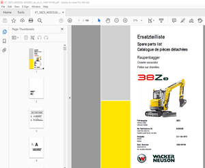
Komatsu Trash Compactor WF650T-3 Shop Manual SEBM027401 – PDF DOWNLOAD
Language : English
Pages : 743
Downloadable : Yes
File Type : PDF
Size: 24.2 MB
IMAGES PREVIEW OF THE MANUAL:


DESCRIPTION:
Komatsu Trash Compactor WF650T-3 Shop Manual SEBM027401 – PDF DOWNLOAD
MACHINE MODEL SERIAL NUMBER
WF650T-3 50001 and up
GENERAL PRECAUTIONS:
Mistakes in operation are extremely dangerous. Read the Operation and Maintenance Manual carefully BEFORE operating the machine.1 .Before carrying out any greasing or repairs, read all the precautions given on the decals which are fixed to the machine.
2.When carrying out any operation, always wear safety shoes and helmet. Do not wear loose work clothes, or clothes with buttons missing.
- Always wear safety glasses when hitting parts with a hammer.
- Always wear safety glasses when grinding parts with a grinder, etc.
3. If welding repairs are needed, always have a trained, experienced welder carry out the work. When carrying out welding work, always wear welding gloves, apron, glasses, cap and other clothes suited for welding work.4.When carrying out any operation with two or more workers, always agree on the op- erating procedure before starting. Always inform your fellow workers before starting any step of the operation. Before starting work, hang UNDER REPAIR signs on the controls in the operator’s compartment.5. Keep all tools in good condition and learn the correct way to use them.
6. Decide a place in the repair workshop to keep tools and removed parts. Always keep the tools and parts in their correct places. Always keep the work area clean and make sure that there is no dirt or oil on the floor. Smoke only in the areas provided for smoking. Never smoke while working.PREPARATIONS FOR WORK:
7. Before adding or making any repairs, park the machine on hard, level ground, and block the wheels to
prevent the machine from moving.
8. Before starting work, lower outrigger, bucket or any other work equipment to the ground. If this is not possible,
use blocks to prevent the work equipment from falling down. In addition, be sure to lock all the control levers and hang warning sign on them.
9. When disassembling or assembling, support the machine with blocks, jacks or stands before starting
work.
10. Remove all mud and oil from the steps or other places used to get on and off the machine. Always use the handrails, ladders or steps when getting on or off the machine.Never jump on or off the machine. If it is impossible to use the handrails, ladders or steps, use a stand to provide safe footing.
TABLE OF CONTENTS:
Komatsu Trash Compactor WF650T-3 Shop Manual SEBM027401 – PDF DOWNLOAD
COVER…………………………………………………………………………………………………………………………………………………… 1
CONTENTS………………………………………………………………………………………………………………………………………………… 2
01 GENERAL………………………………………………………………………………………………………………………………………………. 27
GENERAL ASSEMBLY DRAWING………………………………………………………………………………………………………………………………. 28
SPECIFICATIONS……………………………………………………………………………………………………………………………………….. 29
WEIGHT TABLE…………………………………………………………………………………………………………………………………………. 32
LIST OF LUBRICANT AND WATER……………………………………………………………………………………………………………………………. 33
10 STRUCTURE AND FUNCTION…………………………………………………………………………………………………………………………………. 35
COOLING SYSTEM……………………………………………………………………………………………………………………………………….. 36
POWER TRAIN SYSTEM……………………………………………………………………………………………………………………………………. 38
TORQUE CONVERTER AND TRANSMISSION PIPING………………………………………………………………………………………………………………… 40
HYDRAULIC CIRCUIT DIAGRAM FOR POWER TRAIN……………………………………………………………………………………………………………….. 42
UBRICATION BYPASS VALVE……………………………………………………………………………………………………………………………….. 44
TORQUE CONVERTER……………………………………………………………………………………………………………………………………… 45
TORQUE CONVERTER REGULATOR VALVE……………………………………………………………………………………………………………………….. 47
TORQUE CONVERTER RELIEF VALVE………………………………………………………………………………………………………………………….. 49
TRANSMISSION…………………………………………………………………………………………………………………………………………. 51
ANSMISSION CONTROL VALVE………………………………………………………………………………………………………………………………. 56
ERGENCY MANUAL SPOOL………………………………………………………………………………………………………………………………….. 68
TRANSFER…………………………………………………………………………………………………………………………………………….. 69
DRIVE SHAFT………………………………………………………………………………………………………………………………………….. 70
CENTER SUPPORT……………………………………………………………………………………………………………………………………….. 71
AXLE………………………………………………………………………………………………………………………………………………… 72
DIFFERENTIAL…………………………………………………………………………………………………………………………………………. 74
FINAL DRIVE………………………………………………………………………………………………………………………………………….. 81
WHEEL (TRIANGLE FOOT TYPE)…………………………………………………………………………………………………………………………….. 82
WHEEL (CHPPER TYPE)…………………………………………………………………………………………………………………………………… 84
AXLE MOUNT, CENTER HINGE PIN…………………………………………………………………………………………………………………………… 85
STEERING PIPING………………………………………………………………………………………………………………………………………. 86
STEERING COLUMN………………………………………………………………………………………………………………………………………. 89
STEERING UNIT (ORBIT-ROLL VALVE)……………………………………………………………………………………………………………………….. 90
STEERING VALVE……………………………………………………………………………………………………………………………………….. 93
TWO-WAY RESTRICTION VALVE………………………………………………………………………………………………………………………………104
STOP VALVE……………………………………………………………………………………………………………………………………………105
BRAKE PIPING………………………………………………………………………………………………………………………………………….107
BRAKE CIRCUIT DIAGRAM………………………………………………………………………………………………………………………………….108
BRAKE VALVE…………………………………………………………………………………………………………………………………………..110
CHARGE VALVE………………………………………………………………………………………………………………………………………….115
ACCUMULATOR (FOR BRAKE)………………………………………………………………………………………………………………………………..119
SLACK ADJUSTER………………………………………………………………………………………………………………………………………..120
BRAKE………………………………………………………………………………………………………………………………………………..123
PARKING BRAKE…………………………………………………………………………………………………………………………………………125
SPRING CYLINDER……………………………………………………………………………………………………………………………………….127
PARKING BRAKE SOLENOID VALVE……………………………………………………………………………………………………………………………128
HYDRAULIC PIPING………………………………………………………………………………………………………………………………………129
HYDRAULIC CIRCUIT DIAGRAM………………………………………………………………………………………………………………………………130
WORK EQUIPMENT LEVER LINKAGE……………………………………………………………………………………………………………………………134
HYDRAULIC TANK………………………………………………………………………………………………………………………………………..135
ACCUMULATOR (FOR PPC VALVE)…………………………………………………………………………………………………………………………….138
PPC VALVE…………………………………………………………………………………………………………………………………………….139
PPC RELIEF VALVE………………………………………………………………………………………………………………………………………144
WORK EQUIPMENT VALVE…………………………………………………………………………………………………………………………………..146
AIR CONDITIONER……………………………………………………………………………………………………………………………………….155
MACHINE MONITOR SYSTEM…………………………………………………………………………………………………………………………………158
MAIN MONITOR………………………………………………………………………………………………………………………………………….159
MAINTENANCE MONITOR……………………………………………………………………………………………………………………………………163
ENGINE STARTING CIRCUIT………………………………………………………………………………………………………………………………..165
ENGINE STOP CIRCUIT……………………………………………………………………………………………………………………………………167
AUTO PRIMING SYSTEM (APS)………………………………………………………………………………………………………………………………168
ELECTRIC TRANSMISSION CONTROL…………………………………………………………………………………………………………………………..172
KICK-DOWN SWITCH………………………………………………………………………………………………………………………………………175
KICK-DOWN ELECTRICAL CIRCUIT……………………………………………………………………………………………………………………………176
ELECTRIC PARKING BRAKE CONTROL………………………………………………………………………………………………………………………….182
20 TESTING AND ADJUSTING…………………………………………………………………………………………………………………………………..191
STANDARD VALUE TABLE…………………………………………………………………………………………………………………………………..191
STANDARD VALUE TABLE FOR ENGINE……………………………………………………………………………………………………………………..192
STANDARD VALUE TABLE FOR CHASSIS…………………………………………………………………………………………………………………….193
STANDARD VALUE TABLE FOR ELECTRICAL PARTS…………………………………………………………………………………………………………….198
TESTING AND ADJUSTING………………………………………………………………………………………………………………………………….205
TABLE OF TOOLS FOR TESTING, ADJUSTING, AND TROUBLESHOOTING……………………………………………………………………………………………..206
MEASURING ENGINE SPEED……………………………………………………………………………………………………………………………..207
MEASURING EXHAUST GAS COLOR…………………………………………………………………………………………………………………………209
ADJUSTING VALVE CLEARANCE…………………………………………………………………………………………………………………………..210
MEASURING COMPRESSION PRESSURE………………………………………………………………………………………………………………………211
MEASURING BLOW-BY BRESSURE………………………………………………………………………………………………………………………….212
MEASURING ENGINE OIL PRESSURE……………………………………………………………………………………………………………………….213
TESTING AND ADJUSTING FUEL INJECTION TIMING…………………………………………………………………………………………………………..214
TESTING AND ADJUSTING ALTERNATOR BELT TENSION…………………………………………………………………………………………………………216
TESTING AND ADJUSTING BELT TENSION FOR AIR CONDITIONER COMPRESSOR……………………………………………………………………………………….216
REPLACING FAN BELT ADJUSTING AUTO-TENSIONER…………………………………………………………………………………………………………..217
MEASURING EXHAUST TEMPERATURE……………………………………………………………………………………………………………………….218
MEASURING AIR SUPPLY PRESSURE (BOOST PRESSURE)………………………………………………………………………………………………………..219
ADJUSTING SPEED SENSOR……………………………………………………………………………………………………………………………..220
ADJUSTING FUEL CONTROL CABLE………………………………………………………………………………………………………………………..221
METHOD FOR ADJUSTING ENGINE STOP MOTOR CABLE………………………………………………………………………………………………………….222
TESTING AND ADJUSTING TORQUE CONVERTER, TRANSMISSION OIL PRESSURE……………………………………………………………………………………….224
PROCEDURE FOR FLUSHING TORQUE CONVERTER, TRANSMISSION HYDRAULIC CIRCUIT………………………………………………………………………………….228
PROCEDURE FOR MOVING MACHINE WHEN TRANSMISSION VALVE FAILS……………………………………………………………………………………………..229
TESTING AND ADJUSTING STEERING OIL PRESSURE…………………………………………………………………………………………………………..231
TESTING AND ADJUSTING STEERING STOP VALVE…………………………………………………………………………………………………………….233
TESTING BRAKE OIL PRESSURE………………………………………………………………………………………………………………………….234
MEASURING WEAR OF BRAKE DISC………………………………………………………………………………………………………………………..235
MEASURING BRAKE PERFORMANCE…………………………………………………………………………………………………………………………236
TESTING AND ADJUSTING PARKING BRAKE………………………………………………………………………………………………………………….237
TESTING AND ADJUSTING ACCUMULATOR CHARGE CUT-IN AND CUT-OUT PRESSURE…………………………………………………………………………………….239
TESTING AND ADJUSTING PPC OIL PRESSURE……………………………………………………………………………………………………………….240
TESTING AND ADJUSTING WORK EQUIPMENT HYDRAULIC PRESSURE………………………………………………………………………………………………..242
AJUSTING WORK EQUIPMENT LEVER LINKAGE………………………………………………………………………………………………………………..243
ADJUSTING MAIN MONITOR……………………………………………………………………………………………………………………………..245
BLEEDING AIR………………………………………………………………………………………………………………………………………246
RELEASING REMAINING PRESSURE IN HYDRAULIC CIRCUIT……………………………………………………………………………………………………..247
TROUBLESHOOTING……………………………………………………………………………………………………………………………………….249
POINTS TO REMEMBER WHEN TROUBLESHOOTING………………………………………………………………………………………………………………250
SEQUENCE OF EVENTS IN TROUBLESHOOTING………………………………………………………………………………………………………………..251
POINTS TO REMEMBER WHEN CARRYING OUT MAINTENANCE………………………………………………………………………………………………………252
CHECKS BEFORE TROUBLESHOOTING……………………………………………………………………………………………………………………….260
CONNECTOR TYPES AND MOUNTING LOCATION………………………………………………………………………………………………………………..262
METHOD OF USING TROUBLESHOOTING CHARTS……………………………………………………………………………………………………………….288
METHOD OF USING MATRIX TROUBLESHOOTHING TABLES………………………………………………………………………………………………………..290
TROUBLESHOOTING OF MAIN MONITOR SYSTEM (M MODE)……………………………………………………………………………………………………….293
ELECTRICAL CIRCUIT DIAGRAM FOR MAIN MONITOR……………………………………………………………………………………………………….296
ELECTRICAL CIRCUIT DIAGRAM FOR LAMP AND HORN………………………………………………………………………………………………………298
M- 1 Main monitor does not work………………………………………………………………………………………………………………….299
M- 2 When starting switch is turned ON and engine is started immediately, all lamps stay lighted up……………………………………………………..300
M- 3 Speedometer display does not work properly……………………………………………………………………………………………………301
M- 4 Abnormality in shift in dicator……………………………………………………………………………………………………………..302
a) Displays N even when directional lever is at F………………………………………………………………………………………………302
b) Displays N even when directional lever is at R………………………………………………………………………………………………302
c) Does not display N even when directional lever is at N……………………………………………………………………………………….302
d) Does not display 1st even when speed control lever is at 1st………………………………………………………………………………….303
e) Does not display 2nd even when speed control lever is at 2nd………………………………………………………………………………….303
f) Does not display 3rd even when speed control lever is at 3rd………………………………………………………………………………….303
g) Does not display 4th even when speed control lever is at 4th………………………………………………………………………………….303
M- 5 High beam display does not light up………………………………………………………………………………………………………….305
M- 6 Turn signal display does not light up………………………………………………………………………………………………………..306
a) L.H. turn signal display does not light up………………………………………………………………………………………………….306
b) R.H. turn signal display does not light up………………………………………………………………………………………………….306
M- 7 Abnormality in parking lamp display………………………………………………………………………………………………………….307
a) Parking lamp display does not light up……………………………………………………………………………………………………..307
b) Parking lamp display stays lighted up………………………………………………………………………………………………………307
M- 8 Abnormality in preheating display……………………………………………………………………………………………………………308
a) Preheating display does not light up……………………………………………………………………………………………………….308
b) Preheating display stays lighted up………………………………………………………………………………………………………..308
M- 9 Night lighting of monitor does not light up…………………………………………………………………………………………………..309
M-10 Abnormality in front working lamp……………………………………………………………………………………………………………310
a) Neither monitor display nor front working lamp light up………………………………………………………………………………………310
b) Working lamp lights up but monitor display does not light up………………………………………………………………………………….310
c) Monitor display lights up but working lamp does not light up………………………………………………………………………………….310
M-11 Abnormality in rear working lamp…………………………………………………………………………………………………………….312
a) Neither monitor display nor rear working lamp light up……………………………………………………………………………………….312
b) Working lamp lights up but monitor display does not light up………………………………………………………………………………….312
c) Monitor display lights up but working lamp does not light up………………………………………………………………………………….312
M-12 Abnormality in transmission cut-off………………………………………………………………………………………………………….314
a) When transmission cut-off switch is pressed, cut-of function is not switched and display does not change…………………………………………..314
b) When transmission cut-off switch is turned OFF, cut-off function is always actuated……………………………………………………………..314
c) Transmission cut-off switch is turned ON, but cut-off function is not actuated………………………………………………………………….315
M-13 Abnormality in parking brake dragging warning…………………………………………………………………………………………………316
a) When parking brake is applied, buzzer sounds intermittently and caution lamp flashes even when directional lever is at N…………………………….316
b) When parking brake is applied, buzzer does not sound and caution lamp does not light up even when directional lever is at position other than N………..316
M-14 When parking brake dragging warning is given, buzzer and caution lamp are actuated continuously, or they are not actuated……………………………..317
a) Actuated continuously…………………………………………………………………………………………………………………….317
b) Not actuated…………………………………………………………………………………………………………………………….317
M-15 Abnormality in buzzer………………………………………………………………………………………………………………………318
a) Buzzer does not sound for 3 seconds during self-check when starting switch is turned ON………………………………………………………….318
b) Buzzer always sounds……………………………………………………………………………………………………………………..318
M-16 Condition of monitor switches is not stored in memory………………………………………………………………………………………….319
M-17 Abnormality in emergency steering display…………………………………………………………………………………………………….320
a) Emergency steering display does not flash…………………………………………………………………………………………………..320
b) Emergency steering display stays flashed……………………………………………………………………………………………………320
TROUBLESHOOTING OF MAINTENANCE MONITOR SYSTEM (K MODE)…………………………………………………………………………………………………321
ELECTRICAL CIRCUIT DIAGRAM FOR MAINTENANCE MONITOR…………………………………………………………………………………………………322
K- 1 When starting switch is turned ON, all display on maintenance monitor do not light up for 3 seconds…………………………………………………324
Maintenance monitor does not work…………………………………………………………………………………………………………….324
a) No lamps on maintenance monitor light up……………………………………………………………………………………………………324
b) Some lamps do not light up………………………………………………………………………………………………………………..324
K- 2 When starting switch is turned ON, ail lamps on maintenance monitor light up but do not go out even after 3 seconds…………………………………..325
K- 3 When engine is started immediately after starting switch is turned ON within 3 seconds, no lamps on maintenance monitor go out…………………………326
K- 4 When engine is stopped and starting switch is turned ON, CHECK item display flashes……………………………………………………………….327
a) Engine oil level display flashes…………………………………………………………………………………………………………..327
b) Engine water level display flashes…………………………………………………………………………………………………………328
K- 5 When engine is stopped and starting switch is turned ON, CAUTION item display flashes……………………………………………………………..329
a) Engine oil pressure display flashes………………………………………………………………………………………………………..329
b) Battery charge level display flashes……………………………………………………………………………………………………….330
c) Brake oil pressure display flashes…………………………………………………………………………………………………………331
d) Air cleaner clogged display flashes………………………………………………………………………………………………………..332
K- 6 CAUTION item display is flashing, but caution buzzer does not sound……………………………………………………………………………..333
K- 7 No monitor display lights up, but caution buzzer sounds………………………………………………………………………………………..334
K- 8 CAUTION item display is flashing, but central CHECK lamp or central CAUTION lamp does not flash…………………………………………………….335
a) CHECK lamp………………………………………………………………………………………………………………………………335
b) CAUTION lamp…………………………………………………………………………………………………………………………….335
K- 9 No maintenance monitor display lights up, but central CHECK lamp or central CAUTION lamp lights up………………………………………………….336
a) CHECK lamp………………………………………………………………………………………………………………………………336
b) CAUTION lamp…………………………………………………………………………………………………………………………….336
K-10 Only night lighting of monitor does not light up when lamp switch is turned ON……………………………………………………………………337
K-11 Night lighting of monitor lights up even when lamp switch is OFF………………………………………………………………………………..338
K-12 Service meter does not work…………………………………………………………………………………………………………………339
K-13 Service meter is running even when engine is stopped…………………………………………………………………………………………..339
K-14 Abnormality in gauges………………………………………………………………………………………………………………………340
a) Abnormality in fuel gauge…………………………………………………………………………………………………………………340
b) Abnormality in engine water temperature gauge……………………………………………………………………………………………….341
c) Abnormality in torque converter oil temperature gauge………………………………………………………………………………………..342
TROUBLESHOOTING OF ELECTRICAL SYSTEM (E MODE)………………………………………………………………………………………………………..343
ELECTRICAL CIRCUIT DIAGRAM FOR POWER SUPPLY, ENGINE STARTING, ENGINE STOPPING, APS SYSTEM………………………………………………………………345
ELECTRICAL CIRCUIT DIAGRAM FOR TRANSMISSION AND PARKING BRAKE……………………………………………………………………………………….346
ELECTRICAL CIRCUIT DIAGRAM FOR LAMP AND HORN………………………………………………………………………………………………………347
E-1 Engine does not start……………………………………………………………………………………………………………………….348
a) Starting motor does not turn………………………………………………………………………………………………………………348
b) Starting motor turns……………………………………………………………………………………………………………………..354
E-2 Engine does not stop………………………………………………………………………………………………………………………..357
E-3 Engine stops when machine is traveling………………………………………………………………………………………………………..357
E-4 Abnormality in APS system……………………………………………………………………………………………………………………359
b) When preheating switch is turned AUTO and engine water temperature is below 20℃, preheating lamp flashes, but pilot LED on APS controller shows normal….362
c) After preheating, fuel is not injected from APS nozzle when starting switch is turned START, but pilot LED on APS controller shows normal……………..363
d) LED 1 of pilot LED on APS controller shows abnormal………………………………………………………………………………………….364
e) LED 2 of pilot LED on APS controller shows abnormal………………………………………………………………………………………….364
f) LED 3 of pilot LED on APS controller shows abnormal………………………………………………………………………………………….365
g) LED 4 of pilot LED on APS controller shows abnormal………………………………………………………………………………………….365
h) LED 5 of pilot LED on APS controller shows abnormal………………………………………………………………………………………….366
i) LED 6 of pilot LED on APS controller shows abnormal………………………………………………………………………………………….366
j) When preheating switch is OFF, preheating lamp lights up……………………………………………………………………………………..367
a) When preheating switch is turned AUTO, preheating lamp does not light up, but no pilot LED on APS controller lights up………………………………361
E-5 Parking brake does not have effect……………………………………………………………………………………………………………368
a) Parking brake has no effect when parking brake switch is turned ON…………………………………………………………………………….368
b) Parking brake has no effect and does not work as emergency brake when parking brake pressure drops………………………………………………..368
E-6 Parking brake is applied when machine is traveling……………………………………………………………………………………………..370
E-7 Parking brake is released when starting switch is turned ON……………………………………………………………………………………..372
E-8 Transmission does not change to neutral when parking brake is applied, but parking brake works normally………………………………………………372
E-9 Transmission does not work properly…………………………………………………………………………………………………………..374
a) Abnormality in parking brake circuit, transmission cut-off switch circuit or neutralizer relay circuit…………………………………………….376
b) No continuity in travel FORWARD solenoid circuit…………………………………………………………………………………………….380
c) No continuity in travel REVERSE solenoid circuit…………………………………………………………………………………………….382
d) Short circuit to chassis ground in directional solenoid circuit……………………………………………………………………………….384
e) Abnormality in shift solenoid circuit………………………………………………………………………………………………………390
f) Short circuit to chassis around in shift solenoid circuit…………………………………………………………………………………….393
E-10 Kick-down switch does not work………………………………………………………………………………………………………………398
E-11 Kick-down works only when kick-down switch is being turned ON…………………………………………………………………………………..401
E-12 Kick-down always works……………………………………………………………………………………………………………………..402
E-13 Kick-down switch works even when traveling FORWARD in 2nd………………………………………………………………………………………404
E-14 Power window does not work………………………………………………………………………………………………………………….406
a) Power window does not rise………………………………………………………………………………………………………………..406
b) Power window does not lower……………………………………………………………………………………………………………….407
E-15 Abnormality in front working lamp……………………………………………………………………………………………………………409
E-16 Abnormality in rear working lamp…………………………………………………………………………………………………………….409
E-17 Abnormality in transmission cut-off………………………………………………………………………………………………………….409
E-18 Abnormality in parking brake dragging warning…………………………………………………………………………………………………409
E-19 Abnormality in buzzer………………………………………………………………………………………………………………………409
TROUBLESHOOTING OF HYDRAULIC AND MECHANICAL SYSTEM (H MODE)…………………………………………………………………………………………….411
POWER TRAIN……………………………………………………………………………………………………………………………………412
H- 1 Machine does not start………………………………………………………………………………………………………………….412
H- 2 Travel speed is slow, or lacks power in all speed ranges……………………………………………………………………………………413
H- 3 Excessive time lag when starting machine or shifting gear…………………………………………………………………………………..414
H- 4 Torque converter oil temperature is high………………………………………………………………………………………………….415
H- 5 Steering wheel does not turn…………………………………………………………………………………………………………….416
H- 6 Turning, response of steering is poor…………………………………………………………………………………………………….417
H- 7 Steering is heavy………………………………………………………………………………………………………………………418
H- 8 Steering wheel shakes or jerks…………………………………………………………………………………………………………..419
H- 9 Turning radius is different between left and right at maximum steering……………………………………………………………………….419
BRAKE SYSTEM…………………………………………………………………………………………………………………………………..420
H-10 Wheel brakes do not work or braking effect is poor…………………………………………………………………………………………420
H-11 Wheel brakes are not released or brakes drag………………………………………………………………………………………………422
H-12 Parking brake does not work or braking effect is poor………………………………………………………………………………………423
H-13 Parking brake is not released or brake drags (including emergency release system)……………………………………………………………..424
WORK EQUIPMENT…………………………………………………………………………………………………………………………………425
H-14 Blade does not move…………………………………………………………………………………………………………………….425
H-15 Blade is slow or blade lacks power……………………………………………………………………………………………………….426
H-16 Blade cannot be set to FLOAT or cannot be released from FLOAT……………………………………………………………………………….427
H-17 Blade drops momentarily when control lever is operated from HOLD to RAISE…………………………………………………………………….427
H-18 Excessive hydraulic drift of blade……………………………………………………………………………………………………….428
30 DISASSEMBLY AND ASSEMBLY………………………………………………………………………………………………………………………………..429
METHOD OF USING MANUAL…………………………………………………………………………………………………………………………………431
PRECAUTIONS WHEN CARRYING OUT OPERATION………………………………………………………………………………………………………………….432
SPECIAL TOOL LIST……………………………………………………………………………………………………………………………………..434
SKETCHES OF SPECIAL TOOLS………………………………………………………………………………………………………………………………442
STARTING MOTOR………………………………………………………………………………………………………………………………………..449
Removal and Installation……………………………………………………………………………………………………………………………449
ALTERNATOR……………………………………………………………………………………………………………………………………………450
Removal and Installation……………………………………………………………………………………………………………………………450
ENGINE OIL COOLER……………………………………………………………………………………………………………………………………..451
Removal and Installation……………………………………………………………………………………………………………………………451
FUEL INJECTION PUMP……………………………………………………………………………………………………………………………………452
Removal and Installation……………………………………………………………………………………………………………………………452
WATER PUMP……………………………………………………………………………………………………………………………………………453
Removal and Installation……………………………………………………………………………………………………………………………453
NOZZLE HOLDER…………………………………………………………………………………………………………………………………………454
Removal and Installation……………………………………………………………………………………………………………………………454
TURBOCHARGER………………………………………………………………………………………………………………………………………….455
Removal…………………………………………………………………………………………………………………………………………..455
Installation………………………………………………………………………………………………………………………………………456
ENGINE FRONT SEAL……………………………………………………………………………………………………………………………………..457
Replacement……………………………………………………………………………………………………………………………………….457
ENGINE REAR SEAL………………………………………………………………………………………………………………………………………459
Replacement……………………………………………………………………………………………………………………………………….459
CYLINDER HEAD…………………………………………………………………………………………………………………………………………461
Removal…………………………………………………………………………………………………………………………………………..461
Installation………………………………………………………………………………………………………………………………………466
THERMOSTAT……………………………………………………………………………………………………………………………………………468
Removal and Installation……………………………………………………………………………………………………………………………468
AFTERCOOLER CORE………………………………………………………………………………………………………………………………………469
Removal…………………………………………………………………………………………………………………………………………..469
Installation………………………………………………………………………………………………………………………………………470
RADIATOR……………………………………………………………………………………………………………………………………………..471
Removal…………………………………………………………………………………………………………………………………………..471
Installation………………………………………………………………………………………………………………………………………473
ENGINE AND TORQUE CONVERTER ASSEMBLY…………………………………………………………………………………………………………………….474
Removal…………………………………………………………………………………………………………………………………………..474
Installation………………………………………………………………………………………………………………………………………477
TORQUE CONVERTER ASSEMBLY………………………………………………………………………………………………………………………………478
Removal…………………………………………………………………………………………………………………………………………..478
Installation………………………………………………………………………………………………………………………………………482
Disassembly……………………………………………………………………………………………………………………………………….486
Assembly………………………………………………………………………………………………………………………………………….492
TRANSMISSION………………………………………………………………………………………………………………………………………….499
Removal…………………………………………………………………………………………………………………………………………..499
Installation………………………………………………………………………………………………………………………………………505
Disassembly……………………………………………………………………………………………………………………………………….511
Assembly………………………………………………………………………………………………………………………………………….526
TRANSFER ASSEMBLY……………………………………………………………………………………………………………………………………..542
Disassembly……………………………………………………………………………………………………………………………………….542
Assembly………………………………………………………………………………………………………………………………………….551
CENTER SUPPORT………………………………………………………………………………………………………………………………………..562
Removal and Installation……………………………………………………………………………………………………………………………562
Disassembly……………………………………………………………………………………………………………………………………….564
Assembly………………………………………………………………………………………………………………………………………….566
DRIVE SHAFT…………………………………………………………………………………………………………………………………………..569
Disassembly……………………………………………………………………………………………………………………………………….569
Assembly………………………………………………………………………………………………………………………………………….572
FRONT AXLE……………………………………………………………………………………………………………………………………………575
Removal…………………………………………………………………………………………………………………………………………..575
Installation………………………………………………………………………………………………………………………………………576
FRONT DIFFERENTIAL…………………………………………………………………………………………………………………………………….577
Removal…………………………………………………………………………………………………………………………………………..577
Installation………………………………………………………………………………………………………………………………………578
REAR AXLE…………………………………………………………………………………………………………………………………………….579
Removal…………………………………………………………………………………………………………………………………………..579
Installation………………………………………………………………………………………………………………………………………582
REAR DIFFERENTIAL……………………………………………………………………………………………………………………………………..583
Removal…………………………………………………………………………………………………………………………………………..583
Installation………………………………………………………………………………………………………………………………………584
DIFFERENTIAL GEAR ASSEMBLY……………………………………………………………………………………………………………………………..585
Disassembly……………………………………………………………………………………………………………………………………….585
Assembly………………………………………………………………………………………………………………………………………….589
NON-SPIN DIFFERENTIAL ASSEMBLY………………………………………………………………………………………………………………………….597
Disassembly……………………………………………………………………………………………………………………………………….597
Assembly………………………………………………………………………………………………………………………………………….601
FINAL DRIVE…………………………………………………………………………………………………………………………………………..609
Removal…………………………………………………………………………………………………………………………………………..609
Assembly………………………………………………………………………………………………………………………………………….611
ORBIT-ROLL……………………………………………………………………………………………………………………………………………614
Removal and Installation……………………………………………………………………………………………………………………………614
STEERING CYLINDER……………………………………………………………………………………………………………………………………..615
Removal…………………………………………………………………………………………………………………………………………..615
Installation………………………………………………………………………………………………………………………………………616
Disassembly……………………………………………………………………………………………………………………………………….617
Assembly………………………………………………………………………………………………………………………………………….619
STEERING VALVE………………………………………………………………………………………………………………………………………..621
Removal…………………………………………………………………………………………………………………………………………..621
Installation………………………………………………………………………………………………………………………………………623
BRAKE VALVE…………………………………………………………………………………………………………………………………………..624
Removal and Installation……………………………………………………………………………………………………………………………624
BRAKE VALVE (R.H.)…………………………………………………………………………………………………………………………………….625
Disassembly……………………………………………………………………………………………………………………………………….625
Assembly………………………………………………………………………………………………………………………………………….627
BRAKE VALVE (L.H.)…………………………………………………………………………………………………………………………………….629
Disassembly……………………………………………………………………………………………………………………………………….629
Assembly………………………………………………………………………………………………………………………………………….631
SLACK ADJUSTER………………………………………………………………………………………………………………………………………..633
Removal and Installation……………………………………………………………………………………………………………………………633
Disassembly……………………………………………………………………………………………………………………………………….634
Assembly………………………………………………………………………………………………………………………………………….635
BRAKE………………………………………………………………………………………………………………………………………………..636
Removal and Installation……………………………………………………………………………………………………………………………636
Disassembly……………………………………………………………………………………………………………………………………….637
Assembly………………………………………………………………………………………………………………………………………….640
HYDRAULIC PUMP ASSEMBLY………………………………………………………………………………………………………………………………..644
Removal…………………………………………………………………………………………………………………………………………..644
Installation………………………………………………………………………………………………………………………………………645
HYDRAULIC TANK………………………………………………………………………………………………………………………………………..646
Removal…………………………………………………………………………………………………………………………………………..646
Installation………………………………………………………………………………………………………………………………………648
HYDRAULIC FILTER………………………………………………………………………………………………………………………………………649
Removal and Installation……………………………………………………………………………………………………………………………649
PCC VALVE…………………………………………………………………………………………………………………………………………….650
Removal and Installation……………………………………………………………………………………………………………………………650
Disassembly and Assembly……………………………………………………………………………………………………………………………651
WORK EQUIPMENT VALVE…………………………………………………………………………………………………………………………………..652
Removal…………………………………………………………………………………………………………………………………………..652
Installation………………………………………………………………………………………………………………………………………653
LIFT CYLINDER ASSEMBLY…………………………………………………………………………………………………………………………………654
Removal…………………………………………………………………………………………………………………………………………..654
Installation………………………………………………………………………………………………………………………………………655
CENTER HINGE PIN………………………………………………………………………………………………………………………………………656
Removal…………………………………………………………………………………………………………………………………………..656
Installation………………………………………………………………………………………………………………………………………661
WORK EQUIPMENT ASSEMBLY………………………………………………………………………………………………………………………………..664
Removal and Installation……………………………………………………………………………………………………………………………664
BULKHEAD……………………………………………………………………………………………………………………………………………..665
Removal…………………………………………………………………………………………………………………………………………..665
Installation………………………………………………………………………………………………………………………………………666
FLOOR FRAME…………………………………………………………………………………………………………………………………………..667
Removal…………………………………………………………………………………………………………………………………………..667
Installation………………………………………………………………………………………………………………………………………669
COUNTERWEIGHT…………………………………………………………………………………………………………………………………………670
Removal and Installation……………………………………………………………………………………………………………………………670
FUEL TANK…………………………………………………………………………………………………………………………………………….671
Removal…………………………………………………………………………………………………………………………………………..671
Installation………………………………………………………………………………………………………………………………………672
CAB………………………………………………………………………………………………………………………………………………….673
Removal…………………………………………………………………………………………………………………………………………..673
Installation………………………………………………………………………………………………………………………………………675
STOP VALVE……………………………………………………………………………………………………………………………………………676
Removal and Installation……………………………………………………………………………………………………………………………676
ACCUMULATOR…………………………………………………………………………………………………………………………………………..677
Removal and Installation……………………………………………………………………………………………………………………………677
ACCUMULATOR CHARGE VALVE……………………………………………………………………………………………………………………………….678
Removal and Installation……………………………………………………………………………………………………………………………678
PARKING BRAKE SOLENOID VALVE……………………………………………………………………………………………………………………………679
Removal and Installation……………………………………………………………………………………………………………………………679
PARKING BRAKE…………………………………………………………………………………………………………………………………………680
Removal and Installation……………………………………………………………………………………………………………………………680
PARKING BRAKE CALIPERS…………………………………………………………………………………………………………………………………681
Disassembly……………………………………………………………………………………………………………………………………….681
Assembly………………………………………………………………………………………………………………………………………….682
PARKING BRAKE PAD……………………………………………………………………………………………………………………………………..683
Removal and Installation……………………………………………………………………………………………………………………………683
PEAR STEEL WHEELS……………………………………………………………………………………………………………………………………..684
Removal and Installation……………………………………………………………………………………………………………………………684
AIR CONDITIONER COMPRESSOR……………………………………………………………………………………………………………………………..685
Removal and Installation……………………………………………………………………………………………………………………………685
AIR CONDITIONER CONDENSER………………………………………………………………………………………………………………………………686
Removal and Installation……………………………………………………………………………………………………………………………686
RECEIVER TANK…………………………………………………………………………………………………………………………………………687
Removal and Installation……………………………………………………………………………………………………………………………687
AIR CONDITIONER UNIT…………………………………………………………………………………………………………………………………..688
Removal…………………………………………………………………………………………………………………………………………..688
Installation………………………………………………………………………………………………………………………………………689
MONITOR………………………………………………………………………………………………………………………………………………690
Removal and Installation……………………………………………………………………………………………………………………………690
40 MAINTENANCE STANDARD……………………………………………………………………………………………………………………………………691
ENGINE MOUNT………………………………………………………………………………………………………………………………………….692
TRANSMISSION MOUNT…………………………………………………………………………………………………………………………………….693
TORQUE CONVERTER………………………………………………………………………………………………………………………………………694
TORQUE CONVERTER REGULATOR VALVE………………………………………………………………………………………………………………………..695
TRANSMISSION………………………………………………………………………………………………………………………………………….696
TRANSMISSION SOLENOID VALVE…………………………………………………………………………………………………………………………….699
TRANSMISSION CONTROL VALVE……………………………………………………………………………………………………………………………..700
TRANSFER……………………………………………………………………………………………………………………………………………..704
DRIVE SHAFT…………………………………………………………………………………………………………………………………………..706
CENTER SUPPORT………………………………………………………………………………………………………………………………………..707
DIFFERENTIAL………………………………………………………………………………………………………………………………………….708
FINAL DRIVE…………………………………………………………………………………………………………………………………………..714
AXLE MOUNT……………………………………………………………………………………………………………………………………………717
CENTER HINGE PIN………………………………………………………………………………………………………………………………………718
STEERING COLUMN……………………………………………………………………………………………………………………………………….720
STEERING VALVE………………………………………………………………………………………………………………………………………..721
STEERING CYLINDER MOUNT………………………………………………………………………………………………………………………………..722
BRAKE VALVE…………………………………………………………………………………………………………………………………………..723
SLACK ADJUSTER………………………………………………………………………………………………………………………………………..726
BRAKE………………………………………………………………………………………………………………………………………………..727
PARKING BRAKE…………………………………………………………………………………………………………………………………………728
PPC VALVE…………………………………………………………………………………………………………………………………………….729
WORK EQUIPMENT VALVE…………………………………………………………………………………………………………………………………..730
HYDRAULIC CYLINDER…………………………………………………………………………………………………………………………………….732
WORK EQUIPMENT LINKAGE…………………………………………………………………………………………………………………………………734
ROPS CANOPY…………………………………………………………………………………………………………………………………………..736
90 OTHERS………………………………………………………………………………………………………………………………………………..737
ELECTRIC CIRCUIT DIAGRAM……………………………………………………………………………………………………………………………….739
Electric circuit diagram (1/5)………………………………………………………………………………………………………………………739
Electric circuit diagram (2/5)………………………………………………………………………………………………………………………740
Electric circuit diagram (3/5)………………………………………………………………………………………………………………………741
Electric circuit diagram (4/5)………………………………………………………………………………………………………………………742
Electric circuit diagram (5/5)………………………………………………………………………………………………………………………743
More products