$46
Komatsu WA1200-3 Wheel Loader Shop Manual SEBM018231 – PDF DOWNLOAD
Komatsu WA1200-3 Wheel Loader Shop Manual SEBM018231 – PDF DOWNLOAD
FILE DETAILS:
Komatsu WA1200-3 Wheel Loader Shop Manual SEBM018231 – PDF DOWNLOAD
Language : English
Pages : 2502
Downloadable : Yes
File Type : PDF
Size: 137 MB
TABLE OF CONTENTS:
Komatsu WA1200-3 Wheel Loader Shop Manual SEBM018231 – PDF DOWNLOAD
COVER 1
CONTENTS 2
LIST OF REVISED PAGE 3
00 FOREWORD 17
SAFETY NOTICE 17
HOW TO READ THE SHOP MANUAL 26
EXPLANATION OF TERMS FOR MAINTENANCE STANDARD 28
HOW TO READ ELECTRIC WIRE CODE 30
PRECAUTIONS WHEN CARRYING OUT OPERATION 33
METHOD OF DISASSEMBLING AND CONNECTING PUSH-PULL TYPE COUPLER 36
STANDARD TIGHTENING TORQUE TABLE 39
CONVERSION TABLE 43
01 GENERAL 49
GENERAL ASSEMBLY DRAWING 50
SPECIFICATIONS 51
WEIGHT TABLE 54
LIST OF LUBRICANT AND WATER 56
10 STRUCTURE AND FUNCTION 59
OUTLINE 60
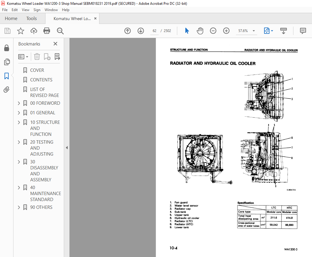
TADIATOR AND HYDRAULIC OIL COOLER 62
DAMPER 63
TORQUE CONVERTER AND TRANSMISSION PIPING 64
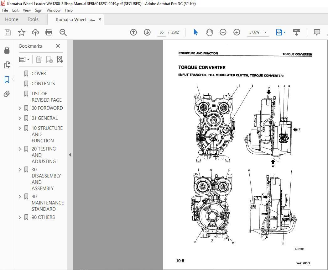
TORQUE CONVERTER 66
MAIN RELIEF VALVE AND TORQUE CONVERTER RELIEF VALVE 74
TORQUE CONVERTER REGULATOR VALVE 78
ECMV 80
TRANSMISSION 86
TRANSMISSION CONTROL VALVE 96
LUBRICATING OIL RELIEF VALVE 107
TRANSFER 108
TORQUE CONVERTER OIL COOLER 110
CENTER SUPPORT 111
AXLE 112
FINAL DRIVE 117
AXLE MOUNT 120
CENTER HINGE PIN 122
JACK-UP POINT 123
ARRANGEMENT OF STEERING EQUIPMENT 125
AJSS (ADVANCED JOYSTICK STEERING SYSTEM) 126
STEERING PUMP 127
SWITCH PUMP 130
SERVO VALVE 133
STEERING DEMAND VALVE 137
ROTARY VALVE 148
EPC VALVE 151
DIVERTER VALVE 152
ARRANGEMENT OF BRAKE EQUIPMENT 156
BRAKE VALVE 158
HARGE VALVE 163
ACCUMULATOR (FOR BRAKE) 167
SLACK ADJUSTER 168
BRAKE 171
PARKING BRAKE 172
PARKING BRAKE OIL CIRCUIT CHECK VALVE ASSEMBLY 174
ARRANGEMENT OF HYDRAULIC EQUIPMENT 178
WORK EQUIPMENT LEVER LINKAGE 180
HYDRAULIC TANK 181
WORK EQUIPMENT PUMP NO 1 184
WORK EQUIPMENT PUMP NO 2 197
WORK EQUIPMENT PUMP NEUTRAL CUT VALVE (NC VALVE) 214
PPC VALVE (PROPORTIONAL PRESSURE VALVE) 216
PPC RELIEF VALVE 220
ACCUMULATOR(FOR PPC VALVE) 221
MAIN CONTROL VALVE 222
WORK EQUIPMENT LINKAGE 236
OPERATION OF PROXIMITY SWITCH 238
AIR CONDITIONER 240
MACHINE MONITOR SYSTEM 243
MAIN MONITOR 247
CGC MONITOR 251
MULTI MONITOR 292
ALL-RANGE ELECTRONIC CONTROL AUTOMATIC TRANSMISSION (ATM) SYSTEM 328
MODULATED CLUTCH (MOD/C) CONTROL SYSTEM 343
WORK EQUIPMENT AND JOYSTICK STEERING CONTROL SYSTEM 347
WORK EQUIPMENT AND JOYSTICK STEERING CONTROLLER 357
ENGINE STARTING CIRCUIT 358
ENGINE STOPPING CIRCUIT 364
ETHER INJECTION CIRCUIT 366
ELECTRIC PARKING BRAKE CONTROL 368
PARKING BRAKE SOLENOID VALVE 378
EMERGENCY PARKING BRAKE RESET SOLENOID VALVE 379
KICK-DOWN SWITCH AND AUTO SHIFT/MANUAL SHIFT SELECTOR SWITCH 380
BATTERY DISCONNECTOR SWITCH 382
EMERGENCY ENGINE STOP SWITCH (FOR RIO TINTO) 384
HYDRAULIC OIL LEVEL CAUTION DISPLAY (FOR RIO TINTO) 387
20 TESTING AND ADJUSTING 391
STANDARD VALUE TABLE 391
STANDARD VALUE TABLE FOR ENGINE 392
STANDARD VALUE TABLE FOR CHASSIS 393
STANDARD VALUE TABLE FOR ELECTRICAL PARTS 399
TESTING AND ADJUSTING 421
ITEMS TO BE PREPARED LIST OF DEVICES FOR TROUBLESHOOTING 424
SAFETY PRECAUTIONS BEFORE STARTING WORK 428
ITEMS RELATED TO ENGINE MEASURING ENGINE SPEED 431
MEASURING EXHAUST GAS COLOR 435
MEASURING BLOW-BY PRESSURE 436
MEASURING ENGINE OIL PRESSURE 438
MEASURING EXHAUST TEMPERATURE 440
MEASURING BOOSTP RESSURE 442
PERFORMANCE CHECK OF RADIATOR 444
MEASURING WIND VELOCITY THROUGH RADIATOR AND OIL COOLER 445
TESTING AND ADJUSTING FAN BELT TENSION 447
TESTING AND ADJUSTING BELT TENSION OF AIR CONDITIONER COMPRESSOR 447
ADJUSTING ROTATION SENSOR 448
POWER TRAIN TESTING AND ADJUSTING TORQUE CONVERTER AND TRANSMISSION OIL PRESSURE 450
TRACTION CONTROL FUNCTION CHECK PROCEDURE 458
PERFORMANCE CHECK OF TORQUE CONVERTER OIL COOLER 459
MEASURING FAN SPEED FOR ADDITIONAL COOLER 460
FLUSHING PROCEDURE FOR HYDRAULIC CIRCUIT OF TORQUE CONVERTER AND TRANSMISSION 461
HOW TO MOVE MACHINE WHEN TRANSMISSION VALVE IS BROKEN 462
HOW TO MEASURE CLEARANCE (PLAY) IN CENTER HINGE BEARING 466
MEASUREMENT PROCEDURE FOR WEAR OF REAR AXLE SUPPORT 468
STEERING SYSTEM TESTING AND ADJUSTING STEERING OIL PRESSURE 469
TESTING AND ADJUSTING EMERGENCY STEERING OIL PRESSURE 471
BLEEDING AIR FROM STEERING CIRCUIT 473
ADJUSTING STEERING STOPPER BOLT 475
ADJUSTING STEERING FOLLOW-UP LINKAGE 476
TESTING STEERING EPC VALVE 481
TESTING AND ADJUSTING STEERING SURGE CUT VALVE OIL PRESSURE 483
TESTING AND ADJUSTING STEERING MAIN RELIEF VALVE OIL PRESSURE 485
MEASURING ROTARY VALVE OUTPUT PRESSURE 489
BRAKE SYSTEM TESTING DROP OF WHEEL BRAKE OIL PRESSURE 491
TESTING WHEEL BRAKE FUNCTION 492
CHECKING SLACK ADJUSTER 493
MEASURING WEAR OF WHEEL BRAKE DISC 495
TESTING AND ADJUSTING CHARGE CUT-IN AND CUT-OUT PRESSURE OF ACCUMULATOR 496
TESTING BRAKE ACCUMULATOR FOR LEAKAGE 500
TESTING EMERGENCY PARKING BRAKE VALVE FOR OIL LEAKAGE 502
TESTING BRAKE VALVE FOR OIL LEAKAGE 504
TESTING BRAKE COOLING OIL PRESSURE 508
PERFORMANCE CHECK OF BRAKE OIL COOLER 510
TESTING PARKING BRAKE PERFORMANCE 511
TESTING WEAR OF PARKING BRAKE DISC 512
HOW TO RESET PARKING BRAKE MANUALLY 513
MEASURING PARKING BRAKE OIL PRESSURE 514
HYDRAULIC EQUIPMENT TESTING AND ADJUSTING WORK EQUIPMENT OIL PRESSURE 515
MEASUREMENT PROCEDURE OF WORK EQUIPMENT OIL PRESSURE WITH OIL PRESSURE GAUGE 519
TESTING AND ADJUSTING PPC OIL PRESSURE 521
ADJUSTING PPC VALVE LINKAGE 526
MEASURING POINTS OF HYDRAULIC PUMP OIL PRESSURE 528
HYDRAULIC PUMP PIPING LINE 530
TESTING AND ADJUSTING PV CONTROL RELIEF VALVE OIL PRESSURE 532
TESTING AND ADJUSTING DIFFERENTIAL PRESSURE VALVE CONTROL OIL PRESSURE 533
TESTING WORK EQUIPMENT PUMP ES VALVE OUTPUT PRESSURE 536
TESTING AND ADJUSTING WORK EQUIPMENT PUMP CO VALVE (CUT-OFF) OIL PRESSURE 538
TESTING WORK EQUIPMENT CONTROL VALVE OPERATION BY WORK EQUIPMENT SPEED (WORK EQUIPMENT SPEED IS LOW) 546
PERFORMANCE CHECK OF HYDRAULIC OIL COOLER (CHECK BY TEMPERATUREDIFFERENCE) 554
PERFORMANCE CHECK OF HYDRAULIC OIL COOLER (CHECK BY MEASURING OIL PRESSURE) 555
BLEEDING AIR FROM EACH PART 559
RELEASING RESIDUAL PRESSURE FROM HYDRAULIC CIRCUIT 566
TESTING OF ACCUMULATOR NITROGEN GAS PRESSURE AND PROCEDURE FOR CHARGING ACCUMULATOR WITH NITROGEN GAS 567
WORK EQUIPMENT SYSTEM CHECKING AND ADJUSTING WORK EQUIPMENT CONTROL LEVER LINKAGE 579
ELECTRICAL EQUIPMENT TESTING AND ADJUSTING BUCKET PROXIMITY SWITCH 583
TESTING AND ADJUSTING LIFT ARM POTENTIOMETER 584
ADJUSTING LIFT ARM HORIZONTAL DETECTION SWITCH 585
PROCEDURE FOR SETTING INITIAL VALUE FOR REMOTE LIFT ARM POSITIONER (METHOD OF INPUTTING BASE POINT) 586
CHECKING PROXIMITY SWITCH ACTUATION PILOT LAMP 589
INITIAL LEARNING METHOD OF TRANSMISSION CONTROLLER 590
ADJUSTING MAIN MONITOR (SPEEDOMETER MODULE) 591
ADJUSTING STEERING LEVER ANGLE AND FRAME ANGLE SENSORS 592
CHECKING AND ADJUSTING INSTALLED POSITIONS OF POTENTIOMETERS 594
PROCEDURE FOR CHECKING DIODE 598
CHECKING GREASING CONDITION OF CENTER HINGE PIN PORTION 599
METHOD OF ADJUSTING AUTO-GREASE INJECTOR DISCHARGE AMOUNT 600
METHOD OF SETTING AUTO-GREASE TIMER 601
VHMS CONTROLLER BASIC PRECAUTIONS 603
TESTING AND MAINTAINING VHMS CONTROLLER 609
VHMS CONTROLLER INITIAL SETTING PROCEDURE 610
PRECAUTIONS FOR REPLACING VHMS CONTROLLER 628
MEASUREMENT PROCEDURE BY DOWNLOADING DATA IN VHMS CONTROLLER 636
MEASUREMENT PROCEDURE BY CGC MONITOR 643
MEASUREMENT PROCEDURE BY MULTI MONITOR 645
SPECIAL FUNCTIONS OF MACHINE CONTROL MONITOR (MULTI MONITOR) 647
OUTLINE OF MEASUREMENT PROCEDURE FOR PM CLINIC 702
PREPARATION FOR MEASUREMENT FOR PM CLINIC 704
Pm clinic check sheet 706
TROUBLESHOOTING 711
POINTS TO REMEMBER WHEN TROUBLESHOOTING 712
SEQUENCE OF EVENTS IN TROUBLESHOOTING 713
CHECKS BEFORE TROUBLESHOOTING 714
TROUBLESHOOTING PROCEDURE FOR WORK EQUIPMENT HYDRAULIC SYSTEM AND STEERING SYSTEM 726
HANDLING OF ELECTRIC EQUIPMENT AND HYDRAULIC COMPONENT 736
CONNECTOR TYPES AND MOUNTING LOCATIONS 745
CONNECTOR ARRANGEMENT DIAGRAM 752
CONNECTION TABLE FOR CONNECTOR PIN NUMBERS 762
T-BRANCH BOX AND T-BRANCH ADAPTER TABLE 798
EXPLANATION OF FUNCTIONS OF ELECTRIC CONTROL MECHANISM 801
METHOD OF DISPLAYING ACTION CODE AND FAILURE CODE 807
FAILURE CODES LIST 820
METHOD OF USING JUDGEMENT TABLE 827
METHOD OF USING TROUBLESHOOTING CHARTS 828
METHOD OF USING MATRIX TROUBLESHOOTING TABLES 830
TROUBLESHOOTING OF ENGINE CONTROLLER SYSTEM (G MODE) 833
DISPLAY METHOD OF CUMMINS ENGINE CONTROLLERFAILURE CODES AND CONTENTS OF DISPLAY 834
FAILURE CODES AND ACTIONS TABLE 835
TROUBLESHOOTING OF TRANSMISSION CONTROLLER SYSTEM (T MODE) 843
JUDGEMENT TABLE FOR TRANSMISSION CONTROL SYSTEM RELATED PARTS 846
OPERATIONS OF CONTROLLER AGAINST ABNORMALITY AND CONDITIONS OF MACHINE CAUSED BY ABNORMALITY 848
ELECTRICAL CIRCUIT DIAGRAM FOR TRANSMISSION CONTROLLER SYSTEM 858
T-1 Failure code [10] (Short circuit, disconnection, short circuit with power source in backup lamp relay) is displayed 860
T-2 Error code [11] (Disconnection in modulated clutch outlet rotation signal sensor system) is displayed 861
T-3 Error code [12] (Short circuit, disconnection, or short circuit with power source in F solenoid system) is displayed 862
T-4 Error code [13] (Short circuit, disconnection, or short circuit with power source in R solenoid system) is displayed 863
T-5 Error code [14] (Short circuit, disconnection, or short circuit with power source in 1st solenoid system) is displayed 864
T-6 Error code [15] (Short circuit, disconnection, or short circuit with power source in 2nd solenoid system) is displayed 865
T-7 Error code [16] (Short circuit, disconnection, or short circuit with power source in 3rd solenoid system) is displayed 866
T-8 Error code [18] (Short circuit, disconnection, or short circuit with power source in R clutch drain valve solenoid system) is displayed 867
T-9 Error code [20] (Short circuit or disconnection in joystick FNR switch system) is displayed 868
T-10 Error code [21] (Short circuit or disconnection in joystick shift-up/shift-down switch system) is displayed 869
T-11 Error code [22] (Disconnection in travel speed sensor system) is displayed 870
T-12 Error code [23] (Short circuit or disconnection in engine speed sensor system) is displayed 871
T-13 Failure code [24] (Short circuit, disconnection in EEP ROM) is displayed 872
T-14 Error code [25] (Short circuit in transmission oil temperature sensor system) is displayed 873
T-15 Error code [26] (Short circuit in F ECMV fill switch system) is displayed 874
T-16 Error code [27] (Short circuit in R ECMV fill switch system) is displayed 874
T-17 Error code [28] (Short circuit in 1st ECMV fill switch system) is displayed 875
T-18 Error code [29] (Short circuit in 2nd ECMV fill switch system) is displayed 875
T-19 Error code [30] (Short circuit in 3rd ECMV fill switch system) is displayed 876
T-20 Error code [32] (Disconnection in F or R ECMV fill switch system) is displayed 877
T-21 Error code [33] (Disconnection in 1st, 2nd, or 3rd ECMV fill switch system) is displayed 878
T-22 Error code [34] (Disconnection or 3rd short circuit with power source in F bypass solenoid system) is displayed 879
T-23 Error code [35] (Short circuit in F bypass solenoid system) is displayed 880
T-24 Error code [36] (Disconnection or short circuit with power source in R bypass solenoid system) is displayed 881
T-25 Error code [37] (Short circuit in R bypass solenoid system) is displayed 882
T-26 Error code [38] (Disconnection or short circuit with power source in 1st bypass solenoid system) is displayed 883
T-27 Error code [39] (Short circuit in 1st bypass solenoid system) is displayed 884
T-28 Auto/Manual selector switch system 885
T-29 Kickdown switch system 885
T-30 Transmission cut-off switch signal system 886
T-31 Steering lock switch signal system 887
T-32 Neutralizer relay signal system 888
T-33 Buzzer signal system 889
T-34 Network system 890
T-35 Transmission controller power supply system 891
T-36 Short circuit in travel speed sensor system 892
T-37 Short circuit in modulated clutch outlet rotation sensor system 893
T-38 Disconnection in transmission oil temperature sensor system 894
T-39 F1 (Forward 1st gear) signal system 895
T-40 Abnormality in auto shift indicator lamp 896
TROUBLESHOOTING OF MODULATED CLUTCH CONTROLLER SYSTEM (MC MODE) 899
JUDGEMENT TABLE FOR MODULATED CLUTCH CONTROL SYSTEM RELATED PARTS 900
OPERATIONS OF CONTROLLER AGAINST ABNORMALITY AND CONDITIONS OF MACHINE CAUSED BY ABNORMALITY 902
ELECTRIC CIRCUIT DIAGRAM OF MODULATED CLUTCH CONTROL SYSTEM 908
MC-1 Error code [70] (Disconnection in boom RAISE/LOWER or bucket TILT/DUMP pressure switch system) is displayed 910
MC-2 Error code [72] (Abnormality in accelerator pedal sensor system) is displayed 912
MC-3 Error code [73] (Short circuit in F/R ECMV fill switch system) is displayed 913
MC-4 Error code [74] (Disconnection in 1st, 2nd, or 3rd ECMV fill switch system) is displayed 914
MC-5 Error code [75] (Short circuit with chassis ground in 1st, 2nd, or 3rd ECMV fill switch system) is displayed 915
MC-6 Error code [76] (Short circuit in RPM-SET IDLE-UP/RESUME IDLE-DOWN switch system) is displayed 916
MC-7 Error code [77] (Short circuit or disconnection in drive force control dial system) is displayed 917
MC-8 Error code [78] (Short circuit or disconnection in travel speed control dial system) is displayed 918
MC-9 Error code [80] (Short circuit or disconnection in wheel rotation sensor system) is displayed 919
MC-10 Error code [81] (Short circuit, disconnection, or short circuit with power source in modulated clutch outlet rotation sensor system) is displayed 920
MC-11 Error code [82] (Short circuit, disconnection, or short circuit with power source in engine speed sensor system) is displayed 921
MC-12 Error code [83] (Short circuit or disconnection in travel speed sensor system) is displayed 922
MC-13 Error code [84] (Short circuit, disconnection, or short circuit with power source in neutral cut solenoid system) is displayed 924
MC-14 Error code [85] (Short circuit, disconnection, or short circuit with power source in modulated clutch ECMV solenoid system) is displayed 925
MC-15 Short circuit in boom RAISE/LOWER or bucket TILT/DUMP pressure switch system 926
MC-16 Disconnection in F ECMV fill switch system 927
MC-17 Disconnection in R ECMV fill switch system 927
MC-18 Disconnection in RPM-SET IDLE-UP/RESUME IDLE-DOWN switch system 928
MC-19 Abnormality in electronic governor voltage command system 929
MC-20 Abnormality in transmission cut-off signal system 930
MC-21 Abnormality in modulated clutch ECMV fill switch system 931
MC-22 Abnormality in right brake pedal switch system 932
MC-23 Abnormality in travel speed control ON/OFF switch system 933
MC-24 Abnormality in RPM-SET ON/OFF switch system 934
MC-25 Abnormality in engine rotation output signal system 935
MC-26 Abnormality in power supply system of modulated clutch control system 936
MC-27 Abnormality in network system 937
MC-28 Abnormality in F1 (Forward 1st gear) input signal system 937
TROUBLESHOOTING OF WORK EQUIPMENT CONTROLLER (JOYSTICK STEERING CONTROL) SYSTEM (J MODE) 939
JUDGEMENT TABLE FOR WORK EQUIPMENT CONTROL SYSTEM RELATED PARTS 940
OPERATIONS OF CONTROLLER AGAINST ABNORMALITY AND CONDITIONS OF MACHINE CAUSED BY ABNORMALITY 942
ELECTRICAL CIRCUIT DIAGRAM FOR JOYSTICK STEERING SYSTEM 946
J-1 Error code [55] (Abnormality in travel speed sensor system) is displayed 947
J-2 Error code [56] (Disconnection or short circuit with chassis ground in caution buzzer relay system) is displayed 948
J-3 Error code [57] (Disconnection or short circuit with chassis ground in steering lever angle sensor system) is displayed 949
J-4 Error code [58] (Deviation of steering lever angle sensor and frame angle sensor potentiometer signals 950
J-5 Error code [59] (Disconnection or short circuit with chassis ground in frame angle sensor system) is displayed 951
J-6 Error code [61] (Disconnection or short circuit with chassis ground in steering lever lock pressure switch system) is displayed 952
J-7 Error code [62] (Disconnection or short circuit with chassis ground in steering neutral interlock relay system) is displayed 953
J-8 Error code [63] (Disconnection, short circuit with chassis ground, or short circuit with power source in steering main pressure control EPC solenoid system) is displayed 954
J-9 Short circuit with chassis ground in travel speed sensor system 955
J-10 Steering speeds in both directions are different 956
J-11 Abnormality in console switch (adjustment of steering lever angle sensor and frame angle sensor is impossible) 957
J-12 Abnormality in power source and voltage 958
TROUBLESHOOTING OF WORK EQUIPMENT CONTROLLER (REMOTE BOOM POSITIONER CONTROL) SYSTEM (W MODE) 959
JUDGEMENT TABLE FOR WORK EQUIPMENT CONTROLLER (REMOTE BOOM POSITIONER CONTROLLER SYSTEM) RELATED PARTS 960
ACTION TAKEN BY CONTROLLER WHEN ABNORMALITY OCCURS AND PROBLEMS ON MACHINE 962
ELECTRICAL CIRCUIT DIAGRAM FOR WORK EQUIPMENT CONTROLLER SYSTEM 964
W-1 Failure code [43] (Short circuit, disconnection in damping solenoid) is displayed 966
W-2 Failure code [44] (Short circuit in power source at hot end of damping solenoid) is displayed 967
W-3 Failure code [45] (Short circuit in power source at return end of damping solenoid) is displayed 967
W-4 Failure code [49] (Short circuit, disconnection in boom lever kick-out relay system) is displayed 968
W-5 Failure code [51] (Disconnection in boom RAISE, LOWER detection pressure switch) is displayed 969
W-6 Failure code [52] (Short circuit, disconnection in boom angle potentiometer system) is displayed 970
W-7 Sensor cannot be adjusted 971
W-8 Abnormality in engine speed signal system 971
W-9 Remote positioner RAISE, LOWER LEDs do not light up 972
W-10 Remote positioner RAISE stop lamp (CGC monitor) does not flash (for 2 5 seconds) 973
W-11 Remote positioner LOWER stop lamp (CGC monitor) does not flash (for 2 5 seconds) 973
W-12 Buzzer for switch operation does not sound 974
W-13 Shock when stopping boom (abnormality in boom lever detent switch) 975
W-14 Short circuit in boom RAISE, LOWER pressure detection switch 976
TROUBLESHOOTING OF MAIN MONITOR SYSTEM (M MODE) 977
TROUBLE DATA DISPLAY 979
ELECTRICAL CIRCUIT DIAGRAM OF MAIN MONITOR SYSTEM 980
M-1 Main monitor does not work 982
M-2 When starting switch is turned ON (within 3 seconds) and engine is started (PRE-LUBE) immediately, all lamps stay lighted up 983
M-3 Speedometer display does not work properly 984
M-4 Abnormality in shift indicator 985
a) Displays N even when directional lever is at F 985
b) Displays N even when directional lever is at R 985
c) Does not display N even when FNR (Forward-reverse) switch is set in N 986
d) Does not display F even when FNR (Forward-reverse) switch is set in F 986
e) Does not display R even when FNR (Forward-reverse) switch is set in R 986
M-5 Turn signal display does not light up 988
a) L H turn signal display does not light up 988
b) R H turn signal display does not light up 988
M-6 Abnormality in parking display 989
a) Parking lamp display does not light up 989
b) Parking lamp display stays lighted up 989
M-7 Night lighting does not light up 990
M-8 Abnormality in front working lamp 991
a) Neither monitor display nor front working lamp light up 991
b) Working lamp lights up but monitor display does not light up 991
c) Monitor display lights up but front working lamp does not light up 991
M-9 Abnormality in rear working lamp 993
a) Neither monitor display nor rear working lamp light up 993
b) Rear working lamp lights up but monitor display does not light up 993
c) Monitor display lights up but working lamp does not light up 993
M-10 Abnormality in transmission cut-off 995
a) When monitor switch (transmission cut-off switch) is pressed, cut-off function is not switched and display does not change 995
b) When monitor switch (transmission cut-off switch) is OFF, monitor display goes out but cut-off function is actuated when pedal is depressed 995
c) When monitor display is turned off (transmission cut-off switch turned OFF), cut-off function is always actuated 995
d) Cut-off function is always actuated regardless of monitor display (transmission cut-off switch ON or OFF) 995
e) Monitor display lights up (transmission cut-off switch turned ON), but cut-off function is not actuated 996
M-11 Abnormality in emergency steering normal display Emergency steering normal display does not light up 997
M-12 Abnormality in emergency steering actuation display 998
a) Emergency steering actuation display does not light up 998
b) Emergency steering actuation display stays lighted up 998
M-13 Abnormality in parking brake dragging warning 999
a) When parking brake is applied, buzzer sounds (intermittently) and CAUTION lamp flashes even when directional lever is at N 999
b) When parking brake is applied, buzzer does not sound and CAUTION lamp does not light up even when directional lever is at position other than N 999
M-14 Abnormality in parking brake dragging warning (When joystick steering mode) 1001
a) When parking brake is applied, buzzer sounds (intermittently) and CAUTION lamp flashes even when directional lever is at N 1001
b) When parking brake is applied, buzzer does not sound and CAUTION lamp does not light up even when directional lever is at position other than N 1001
M-15 When parking brake dragging warning is given, buzzer and CAUTION lamp are actuated continuously, or they are not actuated 1003
a) Actuated continuously 1003
b) Not actuated 1003
M-16 Abnormality in buzzer 1004
a) Buzzer does not sound when starting switch is at ON (for 3 seconds) (during self-check) 1004
b) Buzzer always sounds 1004
M-17 Condition of monitor switches is not stored in memory 1006
M-18 Service meter does not advance or advances while engine is stopped 1007
a) Service meter does not advance 1007
b) Service meter advances while engine is stopped 1007
M-19 Buzzer is not made to sound by transmission controller 1008
M-20 Abnormality in auto-greasing system 1009
a) Forced greasing cannot be carried out 1009
b) Monitor display flashes rapidly (2 times/sec) 1009
c) Monitor display flashes slowly (1 time/sec) 1009
M-21 Failure code is not sent to main monitor (abnormality in network) 1011
TROUBLESHOOTING OF VHMS CONTROLLER SYSTEM (V MODE) 1013
OPERATIONS OF VHMS CONTROLLER AGAINST ABNORMALITY AND CONDITIONS OF MACHINE CAUSED BY ABNORMALITY 1016
LIST OF ALARM ITEMS DISPLAYED ON CGC MONITOR 1032
ELECTRICAL CIRCUIT DIAGRAM FOR VHMS SYSTEM 1034
V-1 [E901] (Engine oil level below LOW level) is displayed 1036
V-2 [E902] (Engine oil pressure below specified pressure) is displayed 1036
V-4 [E904] (Engine coolant temperature above specified temperature) is displayed 1036
V-5 [E905] [Fuel level below specified level (before engine starts)] is displayed 1037
V-6 [E906] [Fuel level below specified level (While engine is running)] is displayed 1039
V-7 [E907] (Torque converter oil temperature above 120°C) is displayed 1041
V-8 [E908] (Torque converter oil temperature above 130°C) is displayed 1042
V-9 [E911] (Hydraulic oil temperature above 105°C) is displayed 1043
V-10 [E912] (Low front or rear brake oil pressure) is displayed 1044
V-11 [E913] (Low front brake oil pressure) is displayed 1046
V-12 [E915] (Low rear brake oil pressure) is displayed 1048
V-13 [916] (Disconnection or short circuit with chassis ground in battery fluid level sensor “1”) is displayed 1050
V-14 [917] (Disconnection or short circuit with chassis ground in battery fluid level sensor “2”) is displayed 1051
V-15 [918] (Disconnection or short circuit with chassis ground in battery fluid level sensor “3”) is displayed 1052
V-16 [E925] [Brake fluid level below specified level (before engine starts)] is displayed 1053
V-17 [E926] [Brake fluid level below specified level (While engine is running)] is displayed 1054
V-18 [E927] [Coolant level below LOW level (before engine starts] is displayed 1055
V-19 [E928] [Coolant level below LOW level (While engine is running)] is displayed 1056
V-20 [E931] (Clogging of transmission oil filter) is displayed 1057
V-21 [E932] [Clogging of air cleaner (1)] is displayed 1059
V-22 [E933] [Clogging of air cleaner (2)] is displayed 1061
V-23 [E934] [Clogging of air cleaner (3)] is displayed 1062
V-24 [E935] [Clogging of air cleaner (4)] is displayed 1063
V-25 [E937] (Abnormal charge by alternator) is displayed 1064
V-101 [E811] (Abnormality in NSW power source system) is displayed in history 1065
V-102 [E812] (Short circuit with chassis ground in 24-V circuit of sensor power supply) 1066
V-103 [E813] (Short circuit with chassis ground in 12-V circuit of sensor power supply) 1068
V-104 [E814] (Short circuit with chassis ground in 5-V circuit of sensor power supply) 1069
V-105 [E818] (Wrong connection of connector) is displayed in history 1070
V-107 [E824] (Communication with CGC and engine controller is impossible) is displayed in history 1071
V-108 [E825] (Abnormality in S-NET communication between VHMS – transmission controller) is displayed in history 1072
V-109 [E826] (Abnormality in S-NET communication between VHMS – modulated clutch controller) is displayed in history 1074
V-110 [E827] (Abnormality in S-NET communication between VHMS – work equipment controller) is displayed in history 1076
V-111 [E828] (Abnormality in S-NET communication between VHMS – main monitor) is displayed in history 1078
V-113 [E841] (Short circuit with power source in buzzer output system) is displayed in history 1081
V-114 [E843] (Short circuit with power source in check lamp system) is displayed in history 1082
V-115 [E844] (Short circuit with power source in flash synchronizing signal system) is displayed in history 1083
V-116 [E861] (Disconnection or short circuit with chassis ground in boom bottom pressure sensor system) is displayed in history 1084
V-117 [E862] (Disconnection or short circuit with chassis ground in boom head pressure sensor system) is displayed in history 1086
V-118 [E863] (Disconnection or short circuit with chassis ground in rear brake oil pressure sensor system) is displayed in history 1088
V-119 [E864] (Disconnection or short circuit with chassis ground in work equipment relief pressure sensor system) is displayed in history 1090
V-120 [E865] (Disconnection or short circuit with chassis ground in front brake oil pressure sensor system) is displayed in history 1092
V-121 [E866] (Disconnection or short circuit with chassis ground in transmission main relief pressure sensor system) is displayed in history 1094
V-122 [E867] (Disconnection or short circuit with chassis ground in steering relief pressure sensor system) is displayed in history 1096
V-123 [E868] (Disconnection or short circuit with chassis ground in torque converter outlet oil pressure sensor system) is displayed in history 1098
V-124 [E871] (Disconnection or short circuit with chassis ground in transmission modulation pressure sensor system) is displayed in history 1100
V-125 [E872] (Disconnection or short circuit with chassis ground in transmission lubricating oil pressure sensor system) is displayed in history 1102
V-126 [E874] (Short circuit with chassis ground in torque converter oil temperature sensor system) is displayed in history 1104
V-127 [E875] (Short circuit with chassis ground and with power source in hydraulic oil temperature sensor system) is displayed in history 1105
V-128 [E877] (Short circuit with chassis ground in ambient temperature sensor system) is displayed in history 1106
V-129 [E878] (Disconnection or short circuit with chassis ground in PPC relief pressure sensor system) is displayed in history 1108
V-130 [E884] (Disconnection or short circuit with chassis ground in torque converter inlet oil pressure sensor system) is displayed in history 1110
V-201 Disconnection or short circuit with power source in 24-V system of sensor power supply 1112
V-202 Disconnection or short circuit with power source in 12-V system of sensor power supply 1114
V-203 Disconnection or short circuit with power source in 5-V system of sensor power supply 1115
V-204 Disconnection or short circuit with chassis ground in buzzer output system 1116
V-205 Disconnection or short circuit with chassis ground in check lamp system 1117
V-206 Disconnection or short circuit with chassis ground in flash synchronizing signal system 1118
V-207 Short circuit with power source in boom bottom pressure sensor system 1119
V-208 Short circuit with power source in boom head pressure sensor system 1120
V-209 Short circuit with power source in rear brake oil pressure sensor system 1121
V-210 Short circuit with power source in front brake oil pressure sensor system 1122
V-211 Short circuit with power source in work equipment relief pressure sensor system 1123
V-212 Short circuit with power source in transmission relief pressure sensor system 1124
V-213 Short circuit with power source in steering relief pressure sensor system 1125
V-214 Short circuit with power source in torque converter outlet oil pressure sensor system 1126
V-215 Short circuit with power source in transmission modulation pressure sensor system 1127
V-216 Disconnection or short circuit with power source in torque converter oil temperature sensor 1128
V-217 Disconnection in hydraulic oil temperature sensor system 1129
V-218 Disconnection in ambient temperature sensor system 1130
V-219 Short circuit with power source in PPC relief sensor system 1131
V-220 Short circuit with chassis ground in fuel level sensor system 1132
V-221 Short circuit with power source in battery fluid level sensor “1” 1133
V-222 Short circuit with power source in battery fluid level sensor “2” 1134
V-223 Short circuit with power source in battery fluid level sensor “3” 1135
V-224 Short circuit with chassis ground or power source in brake fluid level sensor 1136
V-225 Short circuit with power source in coolant level sensor 1137
V-226 Short circuit with chassis ground or power source in transmission oil filter clogging sensor 1138
V-227 Short circuit with power source in air cleaner clogging (1) relay system 1139
V-228 Short circuit with power source in air cleaner clogging (2) relay system 1140
V-229 Short circuit with power source in air cleaner clogging (3) relay system 1140
V-230 Short circuit with power source in air cleaner clogging (4) relay system 1141
V-231 Abnormal charge by alternator 1142
TROUBLESHOOTING OF HYDRAULIC AND MECHANICAL SYSTEM (H MODE) 1143
BEFORE CARRYING OUT TROUBLESHOOTING OF WORK EQUIPMENT HYDRAULIC SYSTEM (HOW TO USE MULTI-MONITOR) 1144
GENERAL TROUBLESHOOTING OF WORK EQUIPMENT HYDRAULIC SYSTEM 1154
WORK EQUIPMENT HYDRAULIC SYSTEM GROUP 1156
BEFORE CARRYING OUT TROUBLESHOOTING OF STEERING HYDRAULIC SYSTEM (HOW TO USE MULTI-MONITOR) 1217
CONFIRMATION ON SPECIFICATION VALUES RELATED TO STEERING (CONFIRMATION OF LOW PERFORMANCE) 1229
GENERAL TROUBLESHOOTING OF STEERING HYDRAULIC SYSTEM 1230
STEERING HYDRAULIC SYSTEM GROUP 1231
GENERAL TROUBLESHOOTING OF BRAKE HYDRAULIC SYSTEM 1271
BRAKE HYDRAULIC SYSTEM GROUP 1272
IMPORTANT TROUBLESHOOTING ITEMS 1324
H-1 Torque converter overheat 1324
H-2 Performance or response of steering is degraded 1326
H-3 Joystick lever is heavy 1328
H-4 Steering is unstable or jolts 1330
H-5 Wheel brake does not work or its performance is low 1332
H-6 Lift arm speed is low or lift arm rising force is insufficient 1334
H-7 Large shocks are made when lift arm stops 1338
H-8 Hydraulic oil overheat 1339
COMMON TROUBLESHOOTING ITEMS 1342
H-1 Machine does not move 1342
H-2 Machine lacks power or speed (every speed range) 1343
H-3 Excessive time lag when starting machine or shifting gear 1344
H-4 Torque converter oil temperature is high 1345
H-4 Torque converter oil temperature is high 1346
H-6 Turning, response of steering is poor 1347
H-7 Joystick lever is heavy 1348
H-8 Steering wheel shakes or jerks 1349
H-9 Turning radius is different between left and right at maximum steering 1350
H-10 Wheel brakes do not work or braking effect is poor 1350
H-11 Wheel brakes are not released or brakes drag 1351
H-12 Boom does not rise 1352
H-13 Boom moves slowly or does not have sufficient lifting power 1353
H-14 When raising boom, becomes slow at certain height 1354
H-15 Boom cylinder cannot hold down bucket 1354
H-16 Boom has large amount of hydraulic drift 1354
H-17 Boom fluctuates while working 1355
H-18 Boom drops momentarily when lever is operated from HOLD to RAISE 1355
H-19 Bucket does not tilt 1356
H-20 Bucket is moves slowly or has insufficient tilt back power 1357
H-21 Bucket movement becomes slow during tilt back 1358
H-22 Bucket cylinder cannot hold down bucket 1358
H-23 Bucket has large amount of hydraulic drift 1358
H-24 Bucket fluctuates while traveling under load (work equipment valve HOLD) 1359
H-25 Bucket dumps momentarily when lever is operated from HOLD to TILT 1359
H-26 Boom and bucket levers do not move smoothly 1360
TROUBLESHOOTING BY FAILUE CODE (DISPLAY OF CODE) 1361
FAILURE CODES LIST 1364
BEFORE CARRYING OUT TROUBLESHOOTING FOR ELECTRICAL SYSTEM1 1373
INFORMATION CONTAINED IN TROUBLESHOOTING TABLE 1376
Failure code [15B0NX] Transmission oil filter clogging 1378
Failure code [2G41MB] Front and rear brake pressure reduction (When engine is started) 1380
Failure code [2G42ZG] Front brake pressure reduction (While engine is running) 1382
Failure code [2G43ZG] Rear brake pressure reduction (While engine is running) 1384
Failure code [AA1ANX] Air cleaner clogging [1] 1386
Failure code [AA1BNX] Air cleaner clogging [2] 1388
Failure code [AA1CNX] Air cleaner clogging [3] 1390
Failure code [AA1DNX] Air cleaner clogging [4] 1392
Failure code [AB00MA] Defective alternator charge 1394
Failure code [B@BCZK] Coolant level reduction (Before engine is started) 1396
Failure code [b@BCZK] Coolant level reduction (While engine is running) 1398
Failure code [B@BFZK] Fuel level reduction (Before engine is started) 1400
Failure code [b@BFZK] Fuel level reduction (While engine is running) 1402
Failure code [B@C5ZK] Brake oil level reduction (Before engine is started) 1404
Failure code [b@C5ZK] Brake oil level reduction (While engine is running) 1405
Failure code [B@CENS] High torque converter oil temperature (above 120°C) 1406
Failure code [b@CENS] Abnormally high torque converter oil temperature (above 130°C) 1407
Failure code [B@GAZK] Battery electrolyte level reduction [1] 1408
Failure code [B@GBZK] Battery electrolyte level reduction [2] 1409
Failure code [B@GCZK] Battery electrolyte level reduction [3] 1410
Failure code [B@HANS] Abnormally high hydraulic oil temperature (overheat) 1411
Failure code [D100KZ] Caution buzzer system abnormality 1412
Failure code [D160KZ] Backup lamp system abnormality 1413
Failure code [D191KZ] Steering neutral interlock relay system abnormality 1414
Failure code [D5ZPKB] Check lamp system abnormality (Hot short) 1415
Failure code [D5ZQKB] Blink synchronizing signal power supply abnormality (Hot short) 1416
Failure code [DAF0KR] Monitor panel (Main monitor) S-net communication error 1417
Failure code [DAQ0KT] Transmission controller abnormality 1419
Failure code [DAQSKR] Transmission controller S-net communication abnormality 1420
Failure code [DB9SKR] Work equipment controller S-net communication error 1422
Failure code [DBB0KK] VHMS power supply abnormality 1424
Failure code [DBB0KQ] VHMS selector connector wrong connection 1426
Failure code [DBB3KK] VHMS backup power supply abnormality 1428
Failure code [DBB5KP] VHMS sensor power supply (5 V) abnormality 1430
Failure code [DBB6KP] VHMS sensor power supply (24 V) abnormality 1431
Failure code [DBB7KP] VHMS sensor power supply (12 V) abnormality 1433
Failure code [DBBQKR] CAN communication error (VHMS controller – multi-monitor) 1434
Failure code [DBBRKR] CAN communication error (J1939) 1435
Failure code [DBCSKR] S-net communication error (MOD/C controller) 1436
Failure code [DBD0KT] Modulated clutch system abnormality 1438
Failure code [DDA7LD] RPM set ON/OFF switch system abnormality 1440
Failure code [DDD7KX] Vehicle speed control dial system abnormality 1442
Failure code [DDD8KX] Drive force control dial system abnormality 1444
Failure code [DDF2KZ] Joystick F, N, R selector switch system abnormality 1446
Failure code [DDF3KZ] Joystick shift up/down switch system abnormality 1448
Failure code [DDNGL4] Boom PPC pressure switch system abnormality 1450
Failure code [DDNJL4] Work equipment PPC pressure switch system abnormality 1452
Failure code [DDQ2L6] Steering lock pressure switch system abnormality 1454
Failure code [DDT8KA] 1st, 2nd or 3rd fill signal system abnormality 1456
Failure code [dDT8KA] Gear speed fill signal abnormality (Disconnection) 1458
Failure code [DDT8KB] Gear speed fill signal abnormality (Ground fault) 1459
Failure code [DDTDKA] F or R fill signal system abnormality (Disconnection) 1460
Failure code [DDTDKB] F or R fill signal system abnormality (Hot short) 1462
Failure code [DDTKKB] 1st fill signal system abnormality 1463
Failure code [DDTLKB] 2nd fill signal system abnormality 1464
Failure code [DDTMKB] 3rd fill signal system abnormality 1465
Failure code [DDTNKB] R fill signal system abnormality 1466
Failure code [DDTQKB] F fill signal system abnormality 1467
Failure code [DGE5KX] Ambient temperature sensor system abnormality 1468
Failure code [DGF1KB] Transmission oil temperature sensor system abnormality 1469
Failure code [DGT1KX] Torque converter oil temperature sensor system abnormality 1470
Failure code [DGT2KX] Hydraulic oil temperature sensor system abnormality 1471
Failure code [DH20KX] Torque converter outlet oil pressure sensor system abnormality 1472
Failure code [DH24KX] Work equipment relief oil pressure sensor system abnormality 1474
Failure code [DHPCKX] Boom bottom pressure sensor system abnormality 1476
Failure code [DHPDKX] Boom head pressure sensor system abnormality 1478
Failure code [DHT3KX] Transmission main pressure sensor system abnormality 1480
Failure code [DHT4KX] Main PPC oil pressure sensor system abnormality 1482
Failure code [DHT5KX] Torque converter inlet oil pressure sensor system abnormality 1484
Failure code [DHT8KX] Steering oil pressure sensor system abnormality 1486
Failure code [DHT9KX] Transmission modulated pressure sensor system abnormality 1488
Failure code [DHTAKX] Transmission lubricating oil pressure sensor system abnormality 1490
Failure code [DHU2KX] Front brake oil pressure sensor system abnormality 1492
Failure code [DHU3KX] Rear brake oil pressure sensor system abnormality 1494
Failure code [DK10L5] Accelerator pedal signal system abnormality 1496
Failure code [DK5FKX] Steering lever angle sensor system abnormality 1498
Failure code [DKA0KX] Boom angle sensor system abnormality 1500
Failure code [DKD0KX] Frame angle sensor system abnormality 1502
Failure code [DKD0KZ] Steering frame angle and lever angle sensors are shifted 1504
Failure code [DLE2KZ] Engine speed sensor system abnormality 1506
Failure code [dLE2KZ] Engine speed sensor system abnormality 1508
Failure code [DLF6L8] Wheel rotation signal system abnormality 1510
Failure code [DLFAKA] Modulated clutch speed sensor system abnormality 1511
Failure code [DLT2KZ] Modulated clutch output speed sensor system abnormality 1512
Failure code [DLT3KZ] Travel speed sensor system abnormality 1514
Failure code [DLt3KZ] Travel speed sensor system abnormality 1516
Failure code [dLT3KZ] Travel speed sensor system abnormality 1518
Failure code [DV00KB] Buzzer output system abnormality (Hot short) 1520
Failure code [DW23KB] F bypass valve system abnormality (Hot short) 1521
Failure code [DW23KZ] F bypass valve system abnormality(Disconnection or hot short) 1522
Failure code [DW24KB] R bypass valve system abnormality (Hot short) 1523
Failure code [DW24KZ] R bypass valve system abnormality (Disconnection or hot short) 1524
Failure code [DW25KB] 1st bypass valve system abnormality (Hot short) 1525
Failure code [DW25KZ] 1st bypass valve system abnormality (Disconnection or hot short) 1526
Failure code [DW72KZ] Boom kick-out solenoid system abnormality 1527
Failure code [DWJ2KZ] R drain valve system abnormality 1528
Failure code [DWNAKZ] Modulation NC solenoid system abnormality 1529
Failure code [DXF0KZ] Steering basic pressure EPC solenoid system abnormality 1531
Failure code [DXH4KZ] Transmission 1st solenoid system abnormality 1532
Failure code [DXH5KZ] Transmission 2nd solenoid system abnormality 1534
Failure code [DXH6KZ] Transmission 3rd solenoid system abnormality 1536
Failure code [DXH7KZ] Transmission R solenoid system abnormality 1538
Failure code [DXH8KZ] Transmission F solenoid system abnormality 1540
Failure code [DXHNKB] Damping solenoid system abnormality (Short circuit) 1542
Failure code [DXHNKY] Damping solenoid system abnormality (Short circuit to power line) 1543
Failure code [DXHNKZ] Damping solenoid system abnormality (Disconnection or short circuit) 1544
Failure code [DXHPKZ] Modulation ECMV solenoid system abnormality 1545
TROUBLESHOOTING OF ELECTRICAL SYSTEM (Without failure code) (E-MODE) 1547
BEFORE CARRYING OUT TROUBLESHOOTING FOR ELECTRICAL SYSTEM 1550
INFORMATION IN TROUBLESHOOTING TABLE 1554
TRANSMISSION CONTROLLER SYSTEM 1556
E-1 Auto/Manual selector switch system abnormality 1556
E-2 Kick-down switch system abnormality 1557
E-3 Transmission cut-off signal system abnormality 1558
E-4 Steering lock switch signal system abnormality 1559
E-5 Neutralizer relay signal abnormality 1560
E-6 Buzzer signal system abnormality 1561
E-7 Network system abnormality 1562
E-8 Transmission controller power supply system abnormality 1564
E-9 Ground fault or short circuit in travel speed sensor system 1565
E-10 Ground fault or short circuit in modulated clutch output speed sensor system 1566
E-11 Disconnection in transmission oil temperature sensor 1567
E-12 F1 (Forward 1st) signal system abnormality 1568
E-13 Auto shift indicator lamp system abnormality 1569
MODULATED CLUTCH CONTROLLER SYSTEM 1571
E-14 Ground fault or short circuit in boom raise/lower or bucket tilt/dump pressure switch system 1571
E-15 Disconnection in F ECMV fill switch system 1572
E-16 Disconnection in R ECMV fill switch system 1573
E-17 Disconnection in RPM set switch 1574
E-18 Electronic governor voltage command system abnormality 1575
E-19 Transmission cut-off signal system abnormality 1576
E-20 Modulated clutch ECMV fill switch system abnormality 1577
E-21 Right brake pedal switch system abnormality 1578
E-22 Travel speed control ON/OFF switch system abnormality 1579
E-23 RPM set ON/OFF switch system abnormality 1580
E-24 Engine speed output signal system abnormality 1581
E-25 Modulated clutch controller power supply abnormality 1582
E-26 Network system abnormality 1583
E-27 F1 (Forward 1st) input signal system abnormality 1583
WORK EQUIPMENT AND JOYSTICK STEERING CONTROLLER SYSTEM (JOYSTICK STEERING CONTROL SYSTEM) 1584
E-28 Ground fault or short circuit in travel speed sensor system 1584
E-29 Right and left steering speeds are different 1586
E-30 Console switch abnormality (Steering lever angle sensor or frame angle sensor cannot be adjusted) 1587
E-31 Power supply voltage abnormality 1588
WORK EQUIPMENT AND JOYSTICK STEERING CONTROLLER SYSTEM (REMOTE BOOM POSITIONER CONTROL SYSTEM) 1589
E-32 Remote positioner sensor cannot be adjusted 1589
E-33 Engine speed signal system abnormality 1590
E-34 Remote positioner “Raise”/”Lower” LED does not light 1591
E-35 Remote positioner “Raise” stop lamp (multi-monitor screen) does not blink (for 2 5 sec) 1592
E-36 Remote positioner “Lower” stop lamp (multi-monitor screen) does not blink (for 2 5 sec) 1592
E-37 Switch operation buzzer does not sound 1593
E-38 Boom stop shocks are made (Boom detent switch abnormality) 1594
E-39 Short circuit in boom “Raise”/”Lower” sensor pressure switch 1596
VHMS CONTROLLER SYSTEM 1598
E-40 Disconnection or hot short in sensor power supply 24 V system 1598
E-41 Disconnection or hot short in sensor power supply 12V system 1600
E-42 Disconnection or hot short in sensor power supply 5 V system 1601
E-43 Disconnection or ground fault in buzzer output system 1602
E-44 Disconnection or ground fault in check lamp system 1603
E-45 Disconnection or ground fault in blink synchronizing signal system 1604
E-46 Hot short in boom bottom pressure sensor system 1605
E-47 Hot short in boom head pressure sensor system 1606
E-48 Hot short in rear brake oil pressure sensor system 1607
E-49 Hot short in front brake oil pressure sensor system 1608
E-50 Hot short in work equipment relief oil pressure sensor system 1609
E-51 Hot short in transmission main relief oil pressure sensor system 1610
E-52 Hot short in steering relief oil pressure sensor system 1611
E-53 Hot short in torque converter outlet oil pressure sensor system 1612
E-54 Hot short in transmission modulated oil pressure sensor system 1613
E-55 Disconnection or hot short in torque converter oil temperature sensor system 1614
E-56 Disconnection in hydraulic oil temperature sensor system 1615
E-57 Disconnection in ambient temperature sensor system 1616
E-58 Hot short in main PPC oil pressure sensor system 1617
E-59 Ground fault in fuel level sensor 1618
E-60 Hot short in battery electrolyte level sensor [1] system 1619
E-61 Hot short in battery electrolyte level sensor [2] system 1620
E-62 Hot short in battery electrolyte level sensor [3] system 1621
E-63 Ground fault or hot short in brake oil level sensor system 1622
E-64 Hot short in coolant level sensor system 1623
E-65 Ground fault or hot short in transmission oil filter sensor system 1624
E-66 Hot short in dust indicator relay [1] system 1625
E-67 Hot short in dust indicator relay [2] system 1626
E-68 Hot short in dust indicator relay [3] system 1627
E-69 Hot short in dust indicator relay [4] system 1628
E-70 Ground fault in alternator charge system 1629
MAIN MONITOR SYSTEM 1630
E-71 Main monitor does not operate 1630
E-72 All main monitor items keep lighting when engine is started (PRE-LUBE) just (within 3 sec) after starting switch is turned ON 1632
E-73 Speedometer does not indicate normally 1636
E-74 Gear shift indicator abnormality 1637
E-75 Winker display does not light 1640
E-76 Parking display abnormality 1641
E-77 Night lamp does not light 1642
E-78 Front working lamp abnormality 1644
E-79 Rear working lamp abnormality 1646
E-80 Transmission cut-off function abnormality 1648
E-81 Emergency steering normal display abnormality 1651
E-82 Emergency steering operation display abnormality 1652
E-83 Parking brake dragging alarm abnormality 1653
E-84 Parking brake dragging alarm abnormality (Joystick steering mode) 1654
E-85 When parking brake dragging alarm is turned ON, buzzer and caution lamp operate continuously or do not operate at all 1656
E-86 Caution buzzer abnormality 1657
E-87 Monitor switch state is not saved 1659
E-88 Service meter does not advance or it advances while engine is stopped 1660
E-89 Transmission controller does not sound buzzer 1662
E-90 Auto grease system abnormality 1663
E-91 Failure code is not transferred to main monitor (Network abnormality) 1665
30 DISASSEMBLY AND ASSEMBLY 1667
How to read this manual 1669
Coating materials list 1671
Special tool list 1674
Sketches of special tools 1679
Procedure for flushing work equipment and steering hydraulic circuit 1725
Procedure for flushing brake hydraulic circuit 1730
Bleeding air from piston pump 1735
Bleeding air from work equipment circuit and steering circuit 1736
Bleeding air from brake circuit 1738
Removal and installation of DT connector pin 1740
Removal and installation of HD connector pin 1742
Repair procedure of HD connector pin harness 1743
Removal and installation of engine assembly 1744
Removal and installation of damper assembly 1772
Disassembly and assembly of damper assembly 1778
Removal and installation of radiator and hydraulic oil cooler assembly 1786
Procedure for disassembly and assembly of MESABI oil cooler assembly 1798
Disassembly and assembly of MESABI oil cooler assembly 1801
Removal and installation of fuel cooler assembly 1809
Removal and installation of torque converter and transmission oil cooler assembly 1814
Removal and installation of bumper and fuel tank assembly 1817
Removal and installation of hood assembly 1820
Removal and installation of bulkhead assembly 1822
Disassembly and assembly of ECMV 1826
Removal and installation of torque converter and transmission assembly 1833
Disconnection and connection of transmission assembly and torque converter assembly 1871
Disconnection and connection of torque converter assembly and PTO • transfer assembly 1880
Disassembly and assembly of torque converter assembly 1883
Disassembly and assembly of modulated clutch assembly 1894
Disassembly and assembly of PTO and transfer assembly 1898
Disconnection and connection of transmission assembly and transfer • parking brake assembly 1912
Disassembly and assembly of transmission assembly 1920
Disassembly and assembly of transfer assembly 1944
Disassembly and assembly of parking brake assembly 1952
Removal and installation of parking brake assembly (from machine body) 1955
Disassembly and assembly of drive shaft assembly 1959
Removal and installation of front axle assembly 1968
Removal and installation of front final drive assembly 1972
Removal and installation of rear axle assembly 1976
Disconnection and connection of differential assembly 1992
Disassembly and assembly of differential assembly 1994
Removal and installation of rear final drive assembly 2004
Disassembly and assembly of final drive and brake assembly 2008
Removal and installation of center support assembly 2020
Disassembly and assembly of center support assembly 2022
Removal and installation of steering demand valve assembly 2026
Removal and installation of steering cylinder assembly 2029
Removal and installation of steering pump, control pump and PPC pump assembly 2035
Removal and installation of switching pump assembly 2042
Removal and installation of emergency diverter valve assembly 2045
Removal and installation of emergency steering pump assembly 2050
Removal and installation of brake accumulator charge valve assembly 2054
Removal and installation of brake oil cooler assembly 2056
Removal and installation of brake oil tank assembly 2059
Removal and installation of transmission, brake cooling and brake pump assembly 2062
Disconnecting procedure for front frame and rear frame 2066
Removal and installation of center hinge pin 2067
Removal and installation of work equipment control valve assembly 2084
Removal and installation of work equipment pump assembly (Right side) 2102
Removal and installation of work equipment pump assembly (Left side) 2106
Removal and installation of hydraulic tank and filter case assembly 2110
Removal and installation of bucket cylinder assembly 2116
Removal and installation of lift cylinder assembly 2130
Disassembly and assembly of hydraulic cylinder assembly 2148
Removal and installation of work equipment assembly 2152
Run-in procedure for bucket pin 2233
Run-in procedure for lift arm pin 2235
Removal and installation of air conditioner unit assembly 2238
Removal and installation of operator’s cab and floor assembly 2240
Removal and installation of operator’s cab assembly 2243
Disassembly and assembly of operator’s seat assembly 2244
Removal and installation of controller assemblies 2277
SERVICE KIT PARTS LIST 2279
40 MAINTENANCE STANDARD 2343
ENGINE MOUNT 2344
TRANSMISSION MOUNT 2346
RADIATOR AND OIL COOLER 2348
DAMPER 2350
TORQUE CONVERTER, TRANSMISSION, BRAKE COOLING AND BRAKE PUMP 2351
INPUT TRANSFER PTO 2354
MODULATED CLUTCH 2356
TORQUE CONVERTER 2357
TRANSMISSION 2358
TRANSFER 2362
MAINRELIEF, TORQUE CONVERTER RELIEF VALVE 2364
TORQUE CONVERTER REGULATOR VALVE 2366
BY-PASS FILL VALVE 2367
BY-PASS FILL VALVE AND BY-PASS DRAIN VALVE 2368
ECMV 2369
LUBRICATIONG OIL RELIEF VALVE 2371
DRIVE SHAFT 2372
CENTER SUPPORT 2373
DIFFERENTIAL 2374
FINAL DRIVE 2378
AXLE MOUNT 2382
CENTER HINGE PIN 2384
STEERING PUMP 2388
SWITCH PUMP 2389
STEERING DEMAND VALVE 2390
DIVERTER VALVE 2392
STEERING CYLINDER MOUNT 2393
EMERGENCY STEERING PUMP 2396
BRAKE VALVE 2397
SLACK ADJUSTER 2399
BRAKE 2400
PARDING BRAKE 2402
WORK EQUIPMENT PUMP NO 1 2404
WORK EQUIPMENT PUMP NO 2 2405
PPC VALVE 2406
PPC RELIEF VALVE 2408
PUMP CONTROL RELIEF VALVE 2409
MAIN CONTROL VALVE 2410
HYDRAULIC CYLINDER 2412
BUCKET POSITIONER AND REMOTE POSITIONER 2415
BUCKET LINKAGE 2416
90 OTHERS 2421
TRANSMISSION HYDRAULIC CIRCUIT DIAGRAM 2422
BRAKE CIRCUIT DIAGRAM 2424
WORK EUIPMENT HYDRAULIC CIRCUIT DIAGRAM (1/2) Serial No : 50001 – 50084 2427
WORK EUIPMENT HYDRAULIC CIRCUIT DIAGRAM (2/2) Serial No : 50001 – 50084 2429
WORK EUIPMENT HYDRAULIC CIRCUIT DIAGRAM (1/2) Serial No : 50085 and up 2431
WORK EUIPMENT HYDRAULIC CIRCUIT DIAGRAM (2/2) Serial No : 50085 and up 2433
ELECTRICAL CIRCUIT DIAGRAM (1/7) Serial No : 50001 – 50038 (Standard specification machine) 2435
ELECTRICAL CIRCUIT DIAGRAM (1/7) Serial No : 50001 – 50038 (Trainer seat specification machine) 2437
ELECTRICAL CIRCUIT DIAGRAM (2/7) Serial No : 50001 – 50038 2439
ELECTRICAL CIRCUIT DIAGRAM (3/7) Serial No : 50001 – 50038 2441
ELECTRICAL CIRCUIT DIAGRAM (4/7) Serial No : 50001 – 50038 2443
ELECTRICAL CIRCUIT DIAGRAM (5/7) Serial No : 50001 – 50038 2445
ELECTRICAL CIRCUIT DIAGRAM (6/7) Serial No : 50001 – 50038 2447
ELECTRICAL CIRCUIT DIAGRAM (7/7) Serial No : 50001 – 50038 2449
ELECTRICAL CIRCUIT DIAGRAM (1/7) Serial No : 50039 – 50074 2451
ELECTRICAL CIRCUIT DIAGRAM (2/7) Serial No : 50039 – 50074 2453
ELECTRICAL CIRCUIT DIAGRAM (3/7) Serial No : 50039 – 50074 2455
ELECTRICAL CIRCUIT DIAGRAM (4/7) Serial No : 50039 – 50074 2457
ELECTRICAL CIRCUIT DIAGRAM (5/7) Serial No : 50039 – 50074 2459
ELECTRICAL CIRCUIT DIAGRAM (6/7) Serial No : 50039 – 50074 2461
ELECTRICAL CIRCUIT DIAGRAM (7/7) Serial No : 50039 – 50074 2463
ELECTRICAL CIRCUIT DIAGRAM (1/8) Serial No : 50075 – 50084, 50086, 50087 2465
ELECTRICAL CIRCUIT DIAGRAM (2/8) Serial No : 50075 – 50084, 50086, 50087 2467
ELECTRICAL CIRCUIT DIAGRAM (3/8) Serial No : 50075 – 50084, 50086, 50087 2469
ELECTRICAL CIRCUIT DIAGRAM (4/8) Serial No : 50075 – 50084, 50086, 50087 2471
ELECTRICAL CIRCUIT DIAGRAM (5/8) Serial No : 50075 – 50084, 50086, 50087 2473
ELECTRICAL CIRCUIT DIAGRAM (6/8) Serial No : 50075 – 50084, 50086, 50087 2475
ELECTRICAL CIRCUIT DIAGRAM (7/8) Serial No : 50075 – 50084, 50086, 50087 2477
ELECTRICAL CIRCUIT DIAGRAM (8/8) Serial No : 50075 – 50084, 50086, 50087 2479
ELECTRICAL CIRCUIT DIAGRAM (1/11) Serial No : 50085, 50088 and up 2481
ELECTRICAL CIRCUIT DIAGRAM (2/11) Serial No : 50085, 50088 and up 2483
ELECTRICAL CIRCUIT DIAGRAM (3/11) Serial No : 50085, 50088 and up 2485
ELECTRICAL CIRCUIT DIAGRAM (4/11) Serial No : 50085, 50088 and up 2487
ELECTRICAL CIRCUIT DIAGRAM (5/11) Serial No : 50085, 50088 and up 2489
ELECTRICAL CIRCUIT DIAGRAM (6/11) Serial No : 50085, 50088 and up 2491
ELECTRICAL CIRCUIT DIAGRAM (7/11) Serial No : 50085, 50088 and up 2493
ELECTRICAL CIRCUIT DIAGRAM (8/11) Serial No : 50085, 50088 and up 2495
ELECTRICAL CIRCUIT DIAGRAM (9/11) Serial No : 50085, 50088 and up 2497
ELECTRICAL CIRCUIT DIAGRAM (10/11) Serial No : 50085, 50088 and up 2499
ELECTRICAL CIRCUIT DIAGRAM (11/11) Serial No : 50085, 50088 and up 2501
DESCRIPTION:
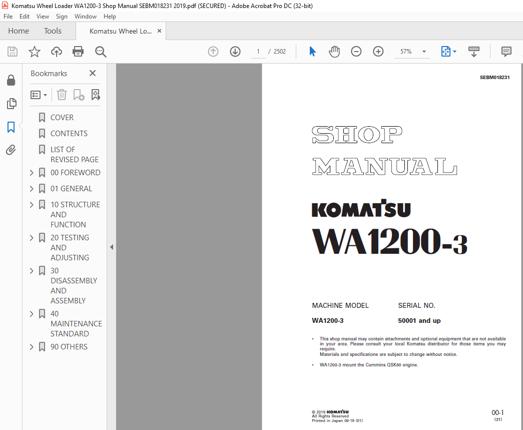
Komatsu WA1200-3 Wheel Loader Shop Manual SEBM018231 – PDF DOWNLOAD
MACHINE MODEL SERIAL NO.
WA1200-3 50001 and up
How to read the shop manual
1. Composition of shop manual
This shop manual contains the necessary technical information for services performed in a workshop.
For ease of understanding, the manual is divided into the following sections.
00. FOREWORD
This section explains the safety and basic information.
01. GENERAL
This section explains the specifications of the machine.
10. STRUCTURE AND FUNCTION
This section explains the structure and function of each component. It serves not only to give an
understanding of the structure, but also serves as reference material for troubleshooting.
In addition, this section may contain hydraulic circuit diagrams, electric circuit diagrams, and maintenance
standards.
20. TESTING AND ADJUSTING
This section explains checks to be made before and after performing repairs, as well as adjustments
to be made at completion of the checks and repairs.
Troubleshooting charts correlating “Problems” with “Causes” are also included in this section.
30. DISASSEMBLY AND ASSEMBLY
This section explains the procedures for removing, installing, disassembling and assembling each
component, as well as precautions for them.
40. MAINTENANCE STANDARD
This section gives the judgment standards for inspection of disassembled parts.
The contents of this section may be described in “STRUCTURE AND FUNCTION”.
90. OTHERS
This section mainly gives hydraulic circuit diagrams and electric circuit diagrams.
In addition, this section may give the specifications of attachments and options together.
VIDEO PREVIEW OF THE MANUAL:
IMAGES PREVIEW OF THE MANUAL:
More products