$45
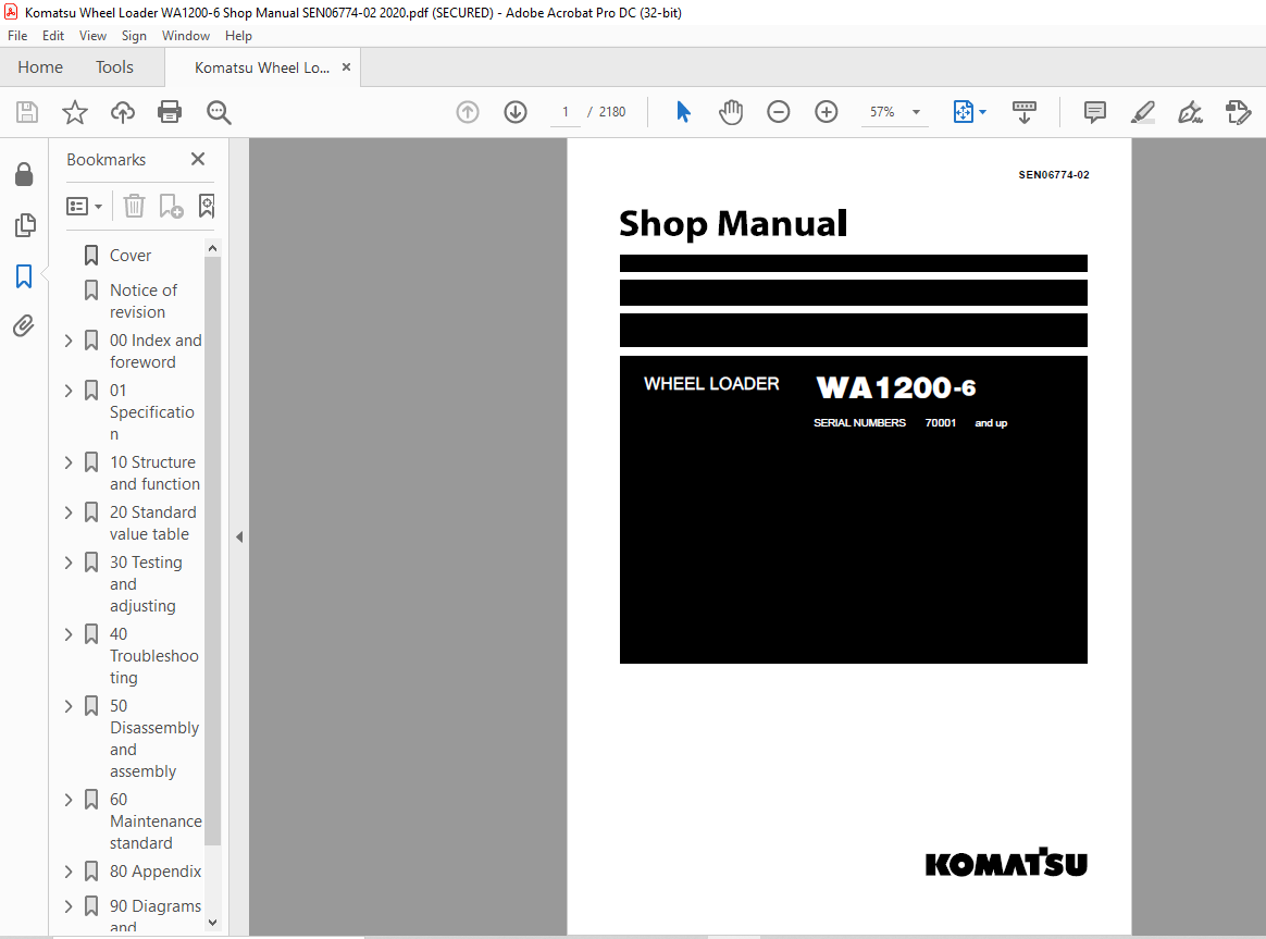
Komatsu WA1200-6 Wheel Loader Shop Manual SEN06774-02 – PDF DOWNLOAD
Komatsu WA1200-6 Wheel Loader Shop Manual SEN06774-02 – PDF DOWNLOAD
FILE DETAILS:
Komatsu WA1200-6 Wheel Loader Shop Manual SEN06774-02 – PDF DOWNLOAD
Language : English
Pages : 2180
Downloadable : Yes
File Type : PDF
Size: 134 MB
DESCRIPTION:
Komatsu WA1200-6 Wheel Loader Shop Manual SEN06774-02 – PDF DOWNLOAD
SERIAL NUMBERS 70001 and up
How to read the shop manual 0-21
1. Composition of shop manual
This shop manual contains the necessary technical information for services performed in a workshop. For
ease of understanding, the manual is divided into the following sections.
00. Index and foreword
This section contains the index, foreword, safety and basic information. If any revision is made, the LIST
OF REVISED PAGES will be added.
01. Specification
This section explains the specifications of the machine.
10. Structure and function
This section explains the structure and function of each component. It serves not only to give an understanding
for the structure of each component, but also serves as reference material for troubleshooting.
20. Standard value table
This section explains the standard values for new machine and judgement criteria for testing, adjusting,
and troubleshooting. This standard value table is used to check the standard values in testing and adjusting
and to judge parts in troubleshooting.
30. Testing and adjusting
This section explains measuring tools and measuring methods for testing and adjusting, as well as the
adjusting method of each part. The standard values and judgment criteria for “Testing and adjusting” are
explained in “Standard value table”.
40. Troubleshooting
This section explains how to find out failed parts and how to repair them. The troubleshooting is divided
by failure modes. The “S mode” of the troubleshooting related to the engine may be also explained in the
Chassis volume and Engine volume. In this case, see the Chassis volume.
50. Disassembly and assembly
This section explains the special tools and procedures for removing, installing, disassembling, and assembling
each component, as well as precautions for them. In addition, tightening torque, and quantity and
weight of coating material, oil, grease, and coolant necessary for the work are also explained.
60. Maintenance standard
This section gives maintenance standard values of each component. The maintenance standard sub-section
explains the criteria and remedies for disassembly and service.
80. Appendix
This section explains the structure, function, testing, adjusting, and troubleshooting for the equipment not
classifiable in other sections.
90. Diagrams and drawings (chassis volume) /Repair and replacement of parts (engine volume)
q Chassis volume
This section gives hydraulic circuit diagrams and electrical circuit diagrams.
q Engine volume
This section explains the method of remanufacturing and repairing engine and replacing parts.
TABLE OF CONTENTS:
Komatsu WA1200-6 Wheel Loader Shop Manual SEN06774-02 – PDF DOWNLOAD
Cover 1
Notice of revision 3
00 Index and foreword 15
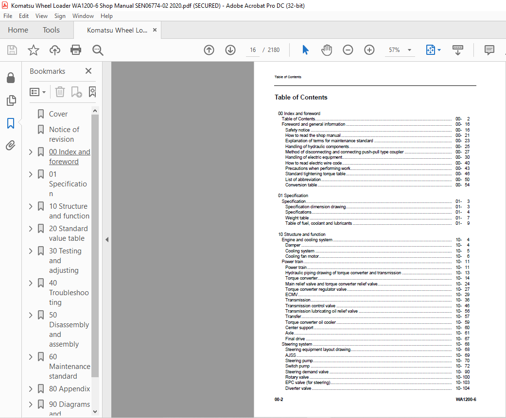
Table of Contents 16
Foreword and general information 30
Safety notice 30
How to read the shop manual 35
Explanation of terms for maintenance standard 37
Handling of hydraulic components 39
Method of disconnecting and connecting push-pull type coupler 41
Handling of electric equipment 44
How to read electric wire code 54
Precautions when performing work 57
Standard tightening torque table 60
List of abbreviation 64
Conversion table 68
01 Specification 73
Contents 74
Specification 75
Specification dimension drawing 75
Specifications 76
Weight table 79
Table of fuel, coolant and lubricants 81
10 Structure and function 83
Contents 84
Engine and cooling system 86
Damper 86
Cooling system 87
Cooling fan motor 88
Power train 93
Power train 93
Hydraulic piping drawing of torque converter and transmission 95
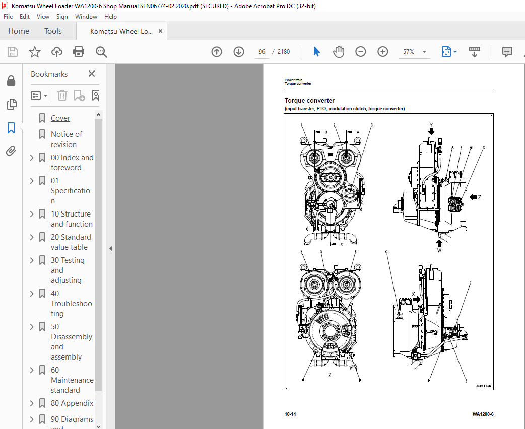
Torque converter 96
Main relief valve and torque converter relief valve 106
Torque converter regulator valve 109
ECMV 111
Transmission 118
Transmission control valve 128
Transmission lubricating oil relief valve 138
Transfer 139
Torque converter oil cooler 141
Center support 142
Axle 143
Final drive 149
Steering system 150
Steering equipment layout drawing 150
AJSS 151
Steering pump 152
Switch pump 154
Steering demand valve 172
Rotary valve 182
EPC valve (for steering) 185
Diverter valve 186
Emergency steering relief valve 189
Steering lock valve 190
Brake system 191
Brake equipment layout drawing 191
Brake valve 192
Charge valve 198
Accumulator (for brake) 202
Slack adjuster 203
Brake 205
Parking brake 206
Parking brake solenoid valve 207
Emergency parking brake release valve 208
Check valve of parking brake circuit 209
Undercarriage and frame 212
Axle mount 212
Center hinge pin 214
Jack-up point 215
Hydraulic system 216
Hydraulic piping layout drawing 216
Work equipment control lever linkage 218
Hydraulic tank 219
Work equipment pump No 1 223
Work equipment pump No 2 236
EPC valve (for work equipment) 260
Neutral cutoff solenoid valve (NC valve) 262
Relief valve 264
Accumulator (for EPC valve) 265
Work equipment control valve 266
Work equipment 280
Work equipment linkage 280
Electrical system 282
Machine monitor system 282
Multi-function monitor 310
Work equipment and AJSS control system 364
Work equipment control lever 400
Transmission control system 403
Engine starting circuit 429
Engine stopping circuit 431
Electric parking brake control 435
Sensor 445
20 Standard value table 467
Contents 468
Standard value table 469
Standard value table for engine 469
Standard value table for chassis 470
30 Testing and adjusting 475
Contents 476
Tool for testing, adjusting and troubleshooting 478
Tools for testing, adjusting, and troubleshooting 478
Safety precautions to follow before starting work 483
Engine and cooling system 487
Testing engine speed 487
Testing exhaust gas color 489
Testing blow-by pressure 490
Measuring engine oil pressure 491
Measuring exhaust gas temperature 492
Testing intake air pressure (boost pressure) 493
Testing radiator performance 494
Measuring wind speed across radiator and oil cooler 495
Testing and adjusting fan belt tension 496
Testing and adjusting air conditioner compressor belt tension 497
Power train 498
Adjusting speed sensor 498
Testing and adjusting torque converter and transmission oil pressure 500
Traction control function checking procedure 503
Testing torque converter oil cooler performance 504
Testing additional cooler fan speed 505
Flushing procedure for torque converter and transmission circuit 506
Retrieval of disabled machine due to transmission valve failure 507
How to measure play of center hinge bearing 510
Measuring wear of rear axle support 512
Steering system 513
Testing and adjusting steering oil pressure 513
Testing and adjusting emergency steering oil pressure 514
Bleeding air from steering circuit 516
Testing and adjusting steering stopper bolt 518
Adjusting steering follow-up linkage 519
Testing steering EPC valve 524
Testing and adjusting steering surge cut valve oil pressure 526
Testing and adjusting steering main relief valve oil pressure 528
Testing rotary valve output pressure 530
Brake system 532
Testing brake performance 532
Testing lowering of wheel brake oil pressure 533
Testing of slack adjuster 534
Measuring wear of wheel brake disc 535
Testing and adjusting accumulator charge pressure 536
Testing brake accumulator oil pressure leakage 538
Testing emergency parking brake valve oil leakage amount 540
Testing brake valve oil leakage amount 543
Testing brake cooling oil pressure 548
Testing brake oil cooler performance 550
Testing parking brake performance 550
Testing wear of parking brake disc 551
Method of releasing parking brake manually 552
Testing parking brake oil pressure 553
Testing of accumulator nitrogen gas pressure and procedure for charging accumulator with nitrogen gas 554
Hydraulic system 564
Testing and adjusting work equipment oil pressure by using multi monitor 564
Testing and adjusting work equipment oil pressure by using oil pressure gauge 566
Testing and adjusting work equipment PPC oil pressure 567
Measuring point of hydraulic pump oil pressure 569
Testing and adjusting PV control relief valve oil pressure 573
Testing and adjusting differential valve output oil pressure 575
Testing work pump ES valve output pressure 577
Testing and adjusting work pump CO (cut-off) valve oil pressure 579
Testing and adjusting work equipment pump TVC valve oil pressure 583
Operation test of work equipment valve by work equipment speed (speed of work equipment is low) 585
Testing hydraulic oil cooler performance 592
Bleeding air from hydraulic circuit 595
Releasing remaining pressure in hydraulic circuit 599
Work equipment 601
Checking center hinge pin lubrication 601
Adjustment method of auto grease injector delivery 603
Setting method of auto grease timer 604
Electrical system 606
Testing and adjusting bucket proximity switch 606
Adjusting lift arm potentiometer 607
Initial setting procedure for remote boom positioner (origin input method) 609
Checking proximity switch operation pilot lamp 610
Adjusting AJSS lever angle sensor and frame angle sensor 611
Testing and adjusting potentiometer mounting position 612
Procedure for testing diodes 615
Basic precautions for KOMTRAX Plus controller 616
Inspection and maintenance of KOMTRAX Plus controller 625
Initial setting procedure for KOMTRAX Plus controller 626
Precautions for replacing KOMTRAX Plus controller 643
Measurement procedure by downloading data in KOMTRAX Plus controller 651
Measurement procedure by multi monitor 655
Special functions of multi monitor 657
Pm Clinic 720
Outline of measurement procedure for Pm Clinic 720
Preparation for measurement for Pm Clinic 721
Pm clinic service 722
40 Troubleshooting 727
Contents 728
General information on troubleshooting 734
Symptom and troubleshooting numbers 734
Sequence of events in troubleshooting 735
Check before troubleshooting 736
Classification and procedures of troubleshooting 747
Breakage of hydraulic cylinder 750
Failure codes table 753
Symptom and troubleshooting numbers 769
Information in troubleshooting table 770
Troubleshooting method for open circuit in wiring harness of pressure sensor system 772
Layout drawing of connector pins 774
Connector list and layout 810
T- branch box and T- branch adapter table 830
Table of fuse locations 833
Troubleshooting by failure code 842
Failure code [1500L0] Double Engagement of Transmission Clutches 842
Failure code [1540N1] T/M overrun 843
Failure code [15B0NX] T/M Oil Filter Clogged 844
Failure code [15SAL1] ECMV (F) Fill Switch Short Circuit 846
Failure code [15SALH] ECMV (F) Fill Switch circuit Disconnect 848
Failure code [15SBL1] ECMV (R) Fill Switch Short Circuit 850
Failure code [15SBLH] ECMV (R) Fill Switch circuit Disconnect 852
Failure code [15SEL1] ECMV (1) Fill Switch Short Circuit 854
Failure code [15SELH] ECMV (1) Fill Switch circuit Disconnect 856
Failure code [15SFL1] ECMV (2) Fill Switch Short Circuit 858
Failure code [15SFLH] ECMV (2) Fill Switch circuit Disconnect 860
Failure code [15SGL1] ECMV (3) Fill Switch Short Circuit 862
Failure code [15SGLH] ECMV (3) Fill Switch circuit Disconnect 864
Failure code [2F00MA] Parking brake circuit failure 867
Failure code [2G42ZG] Accumulator Oil Press F Low 870
Failure code [2G43ZG] Accumulator Oil Press R Low 872
Failure code [44K0L4] Bucket cylinder position detector SW failure 874
Failure code [7REAKA] ACC Signal Malfunction 875
Failure code [989P00] Direction protection warning 876
Failure code [989Q00] Work equipment protection 876
Failure code [989R00] Tire slip 877
Failure code [989S00] Parking Brake Dragging 878
Failure code [989T00] Stationary steering (Brake: OFF, Load: OFF) 880
Failure code [989U00] Stationary steering (Brake: OFF, Load: ON) 881
Failure code [989V00] Stationary steering (Brake: ON, Load: OFF) 882
Failure code [989W00] Stationary steering (Brake: ON, Load: ON) 883
Failure code [AA1ANX] Air Cleaner 1 Clogging 884
Failure code [AA1BNX] Air Cleaner 2 Clogging 886
Failure code [AA1CNX] Air Cleaner 3 Clogging 888
Failure code [AA1DNX] Air Cleaner 4 Clogging 890
Failure code [AB00L6] Discharge of alternator R terminal 892
Failure code [AB00MA] Discharge of alternator R terminal 894
Failure code [AB00MB] Discharge of alternator R terminal 896
Failure code [B@BCZK] Drop in Engine Coolant Level 898
Failure code [b@C5ZK] Low brake fluid level (before engine start) 900
Failure code [B@C5ZK] Low brake fluid level (while engine is running) 901
Failure code [B@C6NS] High brake oil temp 902
Failure code [b@CENS] High torque converter oil temp 903
Failure code [B@CENS] Very high torque converter oil temp 904
Failure code [B@GAZK] Low battery 1 fluid level 906
Failure code [B@GBZK] Low battery 2 fluid level 908
Failure code [B@GCZK] Low battery 3 fluid level 910
Failure code [B@HANS] High hydraulic oil temp 912
Failure code [B@HAZK] Low hydraulic oil level 913
Failure code [D191KA] Neutral Output Relay Disconnection 914
Failure code [D191KB] Neutral Output Relay hot short 916
Failure code [D19MKA] SW pump PNC solenoid Relay (Disconnect/Short Circuit) 918
Failure code [D19MKY] SW pump PNC solenoid Relay hot short 920
Failure code [D19MMA] SW pump PNC solenoid circuit 1 Failure 922
Failure code [D19MMB] SW pump PNC solenoid circuit 2 Failure 924
Failure code [D5ZHKA] Starting Switch C signal circuit (Disconnect/Short Circuit) 926
Failure code [D5ZHKB] Starting Switch C signal circuit Hot short 928
Failure code [D5ZHKZ] Starting Switch C signal circuit failure 930
Failure code [D5ZHL6] Ignition C terminal Circuit Failure 932
Failure code [DAF5KP] Monitor Panel 5 V source sys Error 934
Failure code [DAFRKR] Communication Lost Monitor Panel Controller 936
Failure code [DAQ0KK] Drop in Transmission Controller Main Power Source 938
Failure code [DAQ0KT] Nonvolatile Memory (EEPROM) Abnormal 940
Failure code [DAQ2KK] Drop in Transmission Controller Solenoid Power Source 942
Failure code [DAQRKR] Communication Lost T/M Controller 944
Failure code [DAQRMA] Defective Option Selection Data in Transmission 946
Failure code [DB2RKR] Communication Lost Engine Controller 948
Failure code [DB90KK] Drop in Work Controller Main Power Source 950
Failure code [DB90KT] Nonvolatile Memory (EEPROM) Abnormal 952
Failure code [DB92KK] Solenoid Voltage Failure (Work controller) 954
Failure code [DB95KX] 5 V source sys Error (Work controller) 956
Failure code [DB9RKR] Communication Lost Boom Bucket & Joy stick Controller 958
Failure code [DB9RMA] Defective Option Selection Data in Boom Bucket Controller 960
Failure code [DB9RMC] Communication Lost (Work Controller) 962
Failure code [DBB0KK] VHMS source voltage Error 964
Failure code [DBB0KQ] VHMS Connector Mismatch 966
Failure code [DBB3KK] Abnormality in VBAT voltage (VHMS VBAT<10V) 968
Failure code [DBB5KP] VHMS 5 V source sys Error 970
Failure code [DBB6KP] VHMS 24 V source sys Error 972
Failure code [DBB7KP] VHMS 12 V source sys Error 974
Failure code [DBBQMC] Communication Lost (VHMS CAN0) 976
Failure code [DBBRKR] Communication Lost VHMS Controller 978
Failure code [DBBRMC] Communication Lost (VHMS CAN1) 980
Failure code [DD10KX] Verification Mode SW Failure 982
Failure code [DD1ALD] Remote positioner upper side set sw failure 984
Failure code [DD1BLD] Remote positioner lower side set sw failure 986
Failure code [DDA7L4] Throttle Lock Input signal Short Circuit 988
Failure code [DDA8KB] Throttle Lock (set/accelerator) switch Short Circuit 990
Failure code [DDA9KB] Throttle Lock (set/decelerator) switch Short Circuit 992
Failure code [DDB6L4] Neutral Signal Malfunction 994
Failure code [DDD7KA] Speed control dial circuit (Low Voltage) 996
Failure code [DDD7KB] Speed control dial circuit (High Voltage) 998
Failure code [DDDBKA] Traction control dial circuit (Low Voltage) 1000
Failure code [DDDBKB] Traction control dial circuit (High Voltage) 1002
Failure code [DDE5MA] Emergency steering signal Failure 1004
Failure code [DDK4KA] AJSS F/N/R Input Signal Disconnection 1006
Failure code [DDK4KB] AJSS F/N/R Input Signal Short Circuit 1008
Failure code [DDK5L4] Joystick Shift up/down SW circuit (Disconnect/Short Circuit) 1010
Failure code [DDP5KA] Steering lock detector pressure switch signal circuit Disconnect 1012
Failure code [DDT4LD] T/M Cut Off set switch signal short circuit 1014
Failure code [DDW9LD] Kickdown Switch Short Circuit 1016
Failure code [DGE5KX] Ambient air temp Sensor Failure 1018
Failure code [DGF1KA] Transmission Oil Temperature sensor signal Disconnect 1020
Failure code [DGF1KB] Abnormality in Transmission Oil Temperature sensor Short Circuit 1022
Failure code [DGF1KX] Transmission Oil Temperature sensor Failure (For Check) 1024
Failure code [DGH2KX] Hydraulic oil temp sensor circuit failure 1026
Failure code [DGR2KA] Brake oil temp sensor circuit Disconnection 1028
Failure code [DGR2KX] Brake oil temp sensor circuit failure 1030
Failure code [DGT1KX] T/C oil temp sensor circuit failure 1032
Failure code [DH20KX] Torque converter pressure sensor circuit 1034
Failure code [DH21KA] Loader pump oil press sensor (Disconnect/Short Circuit) 1036
Failure code [DH21KB] Loader pump oil press sensor hot short 1038
Failure code [DHPCKA] Boom bottom press (Disconnect/Short Circuit) 1040
Failure code [DHPCKX] Boom bottom press sensor circuit failure 1042
Failure code [DHPCKY] Boom bottom press hot short 1044
Failure code [DHPDKX] Boom head press sensor circuit failure 1046
Failure code [DHT1KX] T/M Cut Off pressure sensor signal Disconnect 1048
Failure code [DHT2L6] T/M oil filter sensor circuit failure 1050
Failure code [DHT3KX] Transmission main pressure sensor circuit 1052
Failure code [DHT4KX] Main PPC oil pressure sensor circuit 1054
Failure code [DHT5KX] Torque converter intake pressure sensor circuit 1056
Failure code [DHT8KX] Steering Oil Press Sensor Failure 1058
Failure code [DHTAKX] Transmission lubrication pressure sensor circuit 1060
Failure code [DHTBKA] Modulation clutch pressure sensor circuit Disconnect 1062
Failure code [DHTBKB] Modulation clutch pressure sensor signal short circuit 1064
Failure code [DHU2KA] F Brake Oil press Sensor Disconnect 1066
Failure code [DHU2KB] F Brake Oil press Sensor Hot short 1068
Failure code [DHU2KX] F Brake Oil press Sensor Failure 1070
Failure code [DHU3KA] R Brake Oil press Sensor Disconnect 1072
Failure code [DHU3KB] R Brake Oil press Sensor Hot short 1074
Failure code [DHU3KX] R Brake Oil press Sensor Failure 1076
Failure code [DJF1KA] Fuel level sensor circuit Disconnection 1078
Failure code [DK30KA] Steering lever angle sensor (Disconnect/Short Circuit) 1079
Failure code [DK30KY] Steering lever angle sensor circuit hot short 1080
Failure code [DK59KA] Boom lever potentiometer (main) (Disconnect/Short Circuit) 1082
Failure code [DK59KY] Boom lever potentiometer (main) hot short 1084
Failure code [DK59L8] Boom lever potentiometer (main & sub) failure 1085
Failure code [DK5AKA] Boom lever potentiometer (sub) (Disconnect/Short Circuit) 1088
Failure code [DK5AKY] Boom lever potentiometer (sub) hot short 1090
Failure code [DK5BKA] Bucket lever potentiometer (main) (Disconnect/Short Circuit) 1092
Failure code [DK5BKY] Bucket lever potentiometer (main) hot short 1094
Failure code [DK5BL8] Bucket lever potentiometer (main & sub) failure 1095
Failure code [DK5CKA] Bucket lever potentiometer (sub) (Disconnect/Short Circuit) 1098
Failure code [DK5CKY] Bucket lever potentiometer (sub) hot short 1099
Failure code [DKA0KA] Boom angle sensor (Disconnect/Short Circuit) 1100
Failure code [DKA0KX] Boom angle sensor circuit failure 1102
Failure code [DKA0KY] Boom angle sensor circuit hot short 1104
Failure code [DKA0L0] Boom angle sensor failure 1106
Failure code [DKD0KA] Frame angle sensor (Disconnect/Short Circuit) 1108
Failure code [DKD0KY] Frame angle sensor circuit hot short 1109
Failure code [DKD0KZ] Frame and steering angle sensor failure 1110
Failure code [DKH0KA] Angle sensor circuit (FR) Disconnect 1111
Failure code [DKH0KB] Angle sensor circuit (FR) Hot short 1112
Failure code [DKH1KA] Angle sensor circuit (LR) Disconnect 1114
Failure code [DKH1KB] Angle sensor circuit (LR) Hot short 1116
Failure code [DLE2KA] Engine Speed Sensor Disconnection 1118
Failure code [DLE2LC] Engine Speed Sensor Short Circuit 1120
Failure code [DLF6LC] Tire speed sensor circuit 1122
Failure code [DLFAKA] Mod/c Output Speed Sensor Disconnect 1124
Failure code [DLFALC] Mod/c Output Speed Sensor Short Circuit 1126
Failure code [DLT4KB] Output Shaft Speed Sensor (1) Short Circuit 1128
Failure code [DLT4KX] Output Shaft Speed Sensor (1) Disconnection 1130
Failure code [DT20KB] Transmission cut off indicator Output short circuit 1132
Failure code [DT21KB] Speed Control indicator Output short circuit 1133
Failure code [DUM8KB] VHMS Operation lamp Short Circuit 1134
Failure code [DV00KY] Buzzer circuit hotshort (for usually) 1136
Failure code [DV01KY] Buzzer circuit hotshort (for special) 1138
Failure code [DW23KA] T/M E-POCV (F bypass) Solenoid Disconnection 1140
Failure code [DW23KB] T/M E-POCV (F bypass) Solenoid Short Circuit 1141
Failure code [DW23KY] T/M E-POCV (F bypass) Solenoid circuit Hot short 1142
Failure code [DW24KA] T/M E-POCV (R bypass) Solenoid Disconnection 1143
Failure code [DW24KB] T/M E-POCV (R bypass) Solenoid Short Circuit 1144
Failure code [DW24KY] T/M E-POCV (R bypass) Solenoid circuit Hot short 1145
Failure code [DW25KA] T/M E-POCV (1st bypass) Solenoid Disconnection 1146
Failure code [DW25KB] T/M E-POCV (1st bypass) Solenoid Short Circuit 1147
Failure code [DW25KY] T/M E-POCV (1st bypass) Solenoid circuit Hot short 1148
Failure code [DW4PKA] Boom EPC solenoid (raise1) disconnection 1149
Failure code [DW4PKB] Boom Raise EPC solenoid (1) ground fault 1150
Failure code [DW4PKY] Boom Raise EPC solenoid (1) hot short 1151
Failure code [DW4QKA] Boom Lower EPC solenoid (1) disconnection 1152
Failure code [DW4QKB] Boom EPC solenoid (take down1) short circuit 1153
Failure code [DW4QKY] Boom EPC solenoid (take down1) hot short 1154
Failure code [DW4RKA] Bucket tilt EPC solenoid (1) disconnection 1155
Failure code [DW4RKB] Bucket tilt EPC solenoid (1) ground fault 1156
Failure code [DW4RKY] Bucket tilt EPC solenoid (1) hot short 1157
Failure code [DW4SKA] Bucket dump1 EPC solenoid disconnection 1158
Failure code [DW4SKB] Bucket dump EPC solenoid (1) short circuit 1159
Failure code [DW4SKY] Bucket dump EPC solenoid (1) hot short 1160
Failure code [DW5PKA] Boom EPC solenoid (raise2) disconnection 1161
Failure code [DW5PKB] Boom Raise EPC solenoid (2) ground fault 1162
Failure code [DW5PKY] Boom Raise EPC solenoid (2) hot short 1163
Failure code [DW5QKA] Boom EPC solenoid (take down2) disconnection 1164
Failure code [DW5QKB] Boom Lower EPC solenoid (2) ground fault 1165
Failure code [DW5QKY] Boom Lower EPC solenoid (2) hot short 1166
Failure code [DW5RKA] Bucket tilt2 EPC solenoid disconnection 1167
Failure code [DW5RKB] Bucket tilt EPC solenoid ground fault 1168
Failure code [DW5RKY] Bucket tilt2 EPC solenoid hot short 1169
Failure code [DW5SKA] Bucket dump2 EPC solenoid disconnection 1170
Failure code [DW5SKB] Bucket dump2 EPC solenoid short circuit 1171
Failure code [DW5SKY] Bucket dump2 EPC solenoid hot short 1172
Failure code [DWJ2KA] T/M E-POCV (R drain) Solenoid Disconnection 1173
Failure code [DWJ2KB] T/M E-POCV (R drain) Solenoid Short Circuit 1174
Failure code [DWJ2KY] T/M E-POCV (R drain) Solenoid circuit Hot short 1175
Failure code [DWM1KA] Work equipment neutral lock solenoid disconnection 1176
Failure code [DWM1KB] Work equipment neutral lock solenoid short circuit 1177
Failure code [DWM1KY] Work equipment neutral lock solenoid hot short 1178
Failure code [DWN6KA] Magnet detent solenoid (Boom raise) disconnection 1179
Failure code [DWN6KB] Magnet detent solenoid (Boom raise) short circuit 1180
Failure code [DWN6KY] Magnet detent solenoid (Boom raise) hot short 1181
Failure code [DWN7KA] Magnet detent solenoid (Boom float) disconnection 1182
Failure code [DWN7KB] Magnet detent solenoid (Boom float) short circuit 1183
Failure code [DWN7KY] Magnet detent solenoid (Boom float) hot short 1184
Failure code [DWN8KA] Magnet detent solenoid (Bucket tilt) disconnection 1185
Failure code [DWN8KB] Magnet detent solenoid (Boom tilt) short circuit 1186
Failure code [DWN8KY] Magnet detent solenoid (Boom tilt) hot short 1187
Failure code [DWNAKA] NC solenoid disconnection 1188
Failure code [DWNAKB] NC solenoid short circuit 1189
Failure code [DWNAKY] NC solenoid hot short 1190
Failure code [DXA1KA] Loader pump solenoid Relay (Disconnect/Short Circuit) 1192
Failure code [DXA1KY] Loader pump solenoid Relay hot short 1194
Failure code [DXA1MA] Loader pump solenoid Relay (Disconnect/Short Circuit) 1196
Failure code [DXF0KA] AJSS EPC solenoid disconnection 1198
Failure code [DXF0KB] AJSS EPC solenoid short circuit 1200
Failure code [DXH4KA] T/M E-POCV (1st) Solenoid Disconnection 1202
Failure code [DXH4KB] T/M E-POCV (1st) Solenoid Short Circuit 1204
Failure code [DXH4KY] T/M E-POCV (1st) Solenoid circuit Hot short 1206
Failure code [DXH5KA] T/M E-POCV (2nd) Solenoid Disconnection 1208
Failure code [DXH5KB] T/M E-POCV (2nd) Solenoid Short Circuit 1210
Failure code [DXH5KY] T/M E-POCV (2nd) Solenoid circuit Hot short 1212
Failure code [DXH6KA] T/M E-POCV (3rd) Solenoid Disconnection 1214
Failure code [DXH6KB] T/M E-POCV (3rd) Solenoid Short Circuit 1216
Failure code [DXH6KY] T/M E-POCV (3rd) Solenoid circuit Hot short 1218
Failure code [DXH7KA] T/M E-POCV (R) Solenoid Disconnection 1220
Failure code [DXH7KB] T/M E-POCV (R) Solenoid Short Circuit 1222
Failure code [DXH7KY] T/M E-POCV (R) Solenoid circuit Hot short 1224
Failure code [DXH8KA] T/M E-POCV (F) Solenoid Disconnection 1226
Failure code [DXH8KB] T/M E-POCV (F) Solenoid Short Circuit 1228
Failure code [DXH8KY] T/M E-POCV (F) Solenoid circuit Hot short 1230
Failure code [DXHPKA] T/M E-POCV (MOD/C) Solenoid Disconnection 1231
Failure code [DXHPKB] T/M E-POCV (MOD/C) Solenoid Short Circuit 1232
Failure code [DXHPKY] T/M E-POCV (MOD/C) Solenoid Short Circuit to 24 V 1233
Failure code [DXHPMA] T/M E-POCV (MOD/C) Solenoid Malfunction 1234
Troubleshooting of electrical system (E-mode) 1236
E-1 Remote positioner “RAISE” or “LOWER” LED does not light up 1236
E-2 Open circuit or ground fault in check lamp system 1237
E-3 Machine monitor does not operate 1238
E-4 Turn signal lamp does not light up 1240
E-5 Defective parking lamp 1242
E-6 Defective front working lamp 1244
E-7 Defective rear working lamp 1246
E-8 Headlamp does not light up 1248
E-9 Service meter does not work, or service meter works while engine is stopped 1250
E-10 Monitor panel controller does not sound buzzer 1252
E-11 Defective auto-greasing system 1254
Troubleshooting of hydraulic and mechanical system (H-mode) 1256
Before performing troubleshooting of work equipment hydraulic system (how to use the multi monitor) 1256
Work equipment hydraulic system, general 1266
Work equipment oil pressure group 1268
Before performing troubleshooting of steering oil pressure system (how to use the multi monitor) 1333
Checking steering related standard values 1346
Steering oil pressure system, general 1347
Steering oil pressure group 1348
Brake oil pressure system, general 1388
Brake oil pressure group 1390
Information contained in troubleshooting table (H mode) 1444
H-1 Torque converter oil temperature rises too high (overheats) 1445
H-2 Turning or response of steering is poor 1448
H-3 AJSS lever is hard to operate 1451
H-4 Steering shakes or jolts 1453
H-5 Wheel brake does not work at all or is weak 1455
H-6 Lift arm speed is low or lift arm rising force is insufficient 1457
H-7 Shock is large when lift arm stops 1460
H-8 Hydraulic oil temperature rises too high (overheating) 1461
50 Disassembly and assembly 1463
CONTENTS 1464
General information on disassembly and assembly 1466
How to read Disassembly and Assembly 1466
Coating materials list 1468
Special tool list 1471
Sketches of special tools 1485
Flushing procedure 1523
Flushing procedure for brake circuit 1523
Flushing procedure for work equipment and steering circuit 1530
Air bleeding procedure 1537
Bleeding air from brake circuit 1537
Bleeding air from piston motor of brake and torque converter 1538
Bleeding air from piston pump 1540
Bleeding air from work equipment circuit and steering circuit 1541
Engine and cooling system 1544
Removal and installation of radiator and hydraulic oil coolerassembly 1544
Removal and installation of engine assembly 1554
Removal and installation of air-cooled torque converter and transmission,and brake oil cooler assembly 1562
Removal and installation of water-cooled torque converter andtransmission oil cooler assembly 1565
Removal and installation of damper assembly 1567
Disassembly and assembly of damper 1570
Removal and installation of bumper and fuel tank assembly 1579
Removal and installation of hood assembly 1582
Disassembly and assembly procedures for MESABI oil cooler 1584
Disassembly and assembly of MESABI oil cooler 1587
Power train 1597
Removal and installation of torque converter and transmissionassembly 1597
Disconnection and connection of transmission assembly and torqueconverter assembly 1609
Disconnection and connection of torque converter assembly, PTOand transfer assembly 1617
Disassembly and assembly of torque converter 1624
Disassembly and assembly of modulation clutch 1635
Disassembly and assembly of PTO and transfer 1639
Disconnection and connection of transmission assembly,transfer, and parking brake assembly 1652
Disassembly and assembly of transmission assembly 1662
Disassembly and assembly of transfer 1685
Disassembly and assembly of parking brake 1692
Removal and installation of parking brake assembly (installed onthe machine) 1696
Removal and installation of transmission, brake cooling deviceand brake pump assembly 1700
Removal and installation of steering pump, control pump and PPCpump assembly 1702
Disassembly and assembly of drive shaft 1704
Removal and installation of front axle assembly 1706
Removal and installation of front final drive assembly 1709
Removal and installation of rear axle assembly 1713
Removal and installation of rear final drive assembly 1727
Removal and installation of differential assembly 1731
Disassembly and assembly of differential 1734
Disassembly and assembly of final drive and brake 1748
Removal and installation of center support assembly 1763
Disassembly and assembly of center support 1765
Steering system 1770
Removal and installation of steering demand valve assembly 1770
Removal and installation of steering cylinder assembly 1772
Removal and installation of emergency diverter valve assembly 1777
Removal and installation of emergency steering pump assembly 1780
Brake system 1782
Removal and installation of brake accumulator charge valveassembly 1782
Removal and installation of brake oil tank assembly 1783
Undercarriage and frame 1785
Procedure for disconnecting front frame and rear frame 1785
Removal and installation of center hinge pin 1787
Hydraulic system 1806
Removal and installation of hydraulic tank, filter case assembly 1806
Removal and installation of No 1 work equipment pump assembly 1809
Removal and installation of No 2 work equipment pump assembly 1812
Removal and installation of switch pump assembly 1814
Removal and installation of work equipment control valveassembly 1816
Work equipment 1833
Removal and installation of bucket cylinder assembly 1833
Removal and installation of lift cylinder assembly 1845
Disassembly and assembly of work equipment cylinder 1860
Removal and installation of work equipment assembly 1867
Procedure for running in bucket pin 1933
Procedure for running in lift arm pin 1936
Cab 1939
Removal and installation of bulkhead assembly 1939
Removal and installation of operator’s cab and floor assembly 1941
Removal and installation of operator’s cab assembly 1947
Removal and installation of air conditioner unit assembly 1950
Disassembly and assembly of operator seat 1952
Removal and installation of AJSS lever switch assembly 1978
Electrical system 1985
Removal and installation of DT connector pin 1985
Removal and installation of HD connector pin 1987
Repairing HD connector pin harness 1989
Removal and installation of controller assembly 1991
60 Maintenance standard 1993
Contents 1994
Engine and cooling system 1995
Engine mount 1995
Cooling system 1996
Cooling fan motor 1997
Damper 1999
Power train 2000
Transmission mount 2000
Torque converter 2002
Main relief valve, torque converter relief valve 2006
Torque converter regulator valve 2008
ECMV 2009
Transmission 2010
Transmission control valve 2012
Lubrication relief valve 2015
Transfer 2016
Drive shaft 2018
Center support 2020
Differential 2022
Final drive 2026
Steering system 2028
Steering pump 2028
Switch pump 2029
Steering demand valve 2031
Diverter valve 2033
Steering cylinder mount 2034
Steering cylinder 2035
Emergency steering pump 2037
Brake system 2038
Brake valve 2038
Slack adjuster 2040
Brake 2041
Parking brake 2042
Undercarriage and frame 2044
Axle mount 2044
Center hinge pin 2046
Hydraulic system 2049
No 1 work equipment pump 2049
No 2 work equipment pump 2052
PPC relief valve 2055
Pump control relief valve 2056
Work equipment control valve 2057
Work equipment 2059
Work equipment linkage 2059
Bucket positioner, remote positioner 2064
Work equipment cylinder 2065
Electrical system 2067
Work equipment control lever 2067
80 Appendix 2069
Contents 2070
Air conditioner 2071
Precautions for refrigerant 2071
Configuration and function of refrigeration cycle 2072
Outline of refrigeration cycle 2073
Control system 2075
Air conditioner components 2080
Compressor 2087
Electric fan and condenser 2088
Receiver drier 2090
Service tools 2091
Troubleshooting procedures 2098
Interview and confirmation of failure symptom 2099
Basic checks 2100
Troubleshooting 2101
Checking of refrigeration cycle 2107
Troubleshooting for unusual noise 2115
Electrical system 2116
Parts replacement 2118
Periodic inspection and maintenance 2121
Testing and adjusting compressor belt tension 2125
90 Diagrams and drawings 2127
Contents 2128
Hydraulic circuit diagram 2129
Circuit symbols used in hydraulic circuit diagrams 2129
Transmission hydraulic circuit diagram 2132
Brake hydraulic circuit diagram 2134
Work equipment hydraulic circuit diagram 2137
Electrical circuit diagram 2141
Circuit symbols used in electrical circuit diagrams 2141
Electrical circuit diagram 2145
INDEX 2171
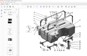
IMAGES PREVIEW OF THE MANUAL:
More products