$43
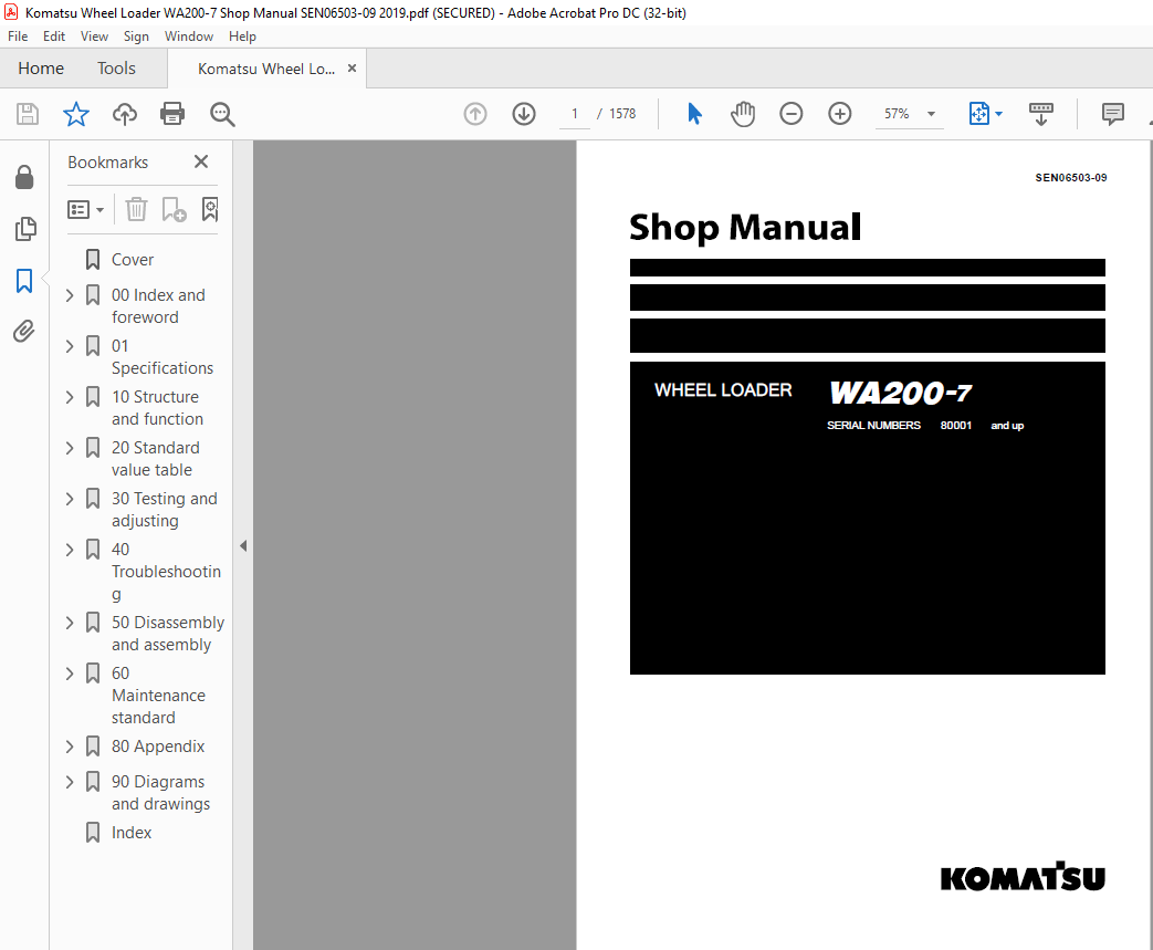
Komatsu WA200-7 Wheel Loader Shop Manual SEN06503-09 – PDF DOWNLOAD
Komatsu WA200-7 Wheel Loader Shop Manual SEN06503-09 – PDF DOWNLOAD
FILE DETAILS:
Komatsu WA200-7 Wheel Loader Shop Manual SEN06503-09 – PDF DOWNLOAD
Language : English
Pages : 1578
Downloadable : Yes
File Type : PDF
Size: 123 MB
DESCRIPTION:
Komatsu WA200-7 Wheel Loader Shop Manual SEN06503-09 – PDF DOWNLOAD
SERIAL NUMBERS 80001 and up
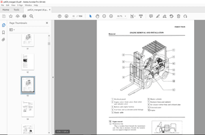
General precautions:
• Before performing any greasing or repairs, read all the safety labels stuck to the machine. For the locations of the safety labels and detailed explanation of precautions, see the operation and maintenance manual.• Locate a place in the repair workshop to keep the tools and removed parts. Always keep the tools and parts in their correct places. Always keep the work area clean and make sure that there is no dirt, water or oil on the floor. Smoke only in the areas provided for smoking. Never smoke while working.• When performing any work, always wear the safety shoes and helmet. Do not wear loose work cloths, or clothes with buttons missing. 1. Always wear the protective eyeglasses when hitting parts with a hammer.Always wear the protective eyeglasses when grinding parts with a grinder, etc.• When performing any work with 2 or more workers, always agree on the working procedure before starting. While working, always keep conversations of the work between your fellow workers and your self on any step of the work. During the work, hang the warning tag of “UNDER WORKING” in the operator’s compartment.• Only qualified workers must perform the work and operation which require license or qualification.• Keep the tools in good condition. And learn the correct way to use the tools, and use the proper ones among them. Before starting the work, thoroughly check the tools, lift truck, service vehicle, etc.• If welding repairs is required, always have a trained and experienced welder with good knowledge of welding perform the work. When performing welding work, always wear welding gloves, apron, shielding goggles, cap, etc.• Before starting work, warm up your body thoroughly to start work under good condition.• Avoid continuing work for long hours and take rests with proper intervals to keep your body in good condition. Take a rest in a specified safe place.
How to read the shop manual :
• Some attachments and optional parts described in this shop manual may not be arranged for certain
areas. Contact your Komatsu distributor if one or some of them are required.
• Materials and specifications are subject to change without notice.
• The shop manuals are available for “Machine part” and “Engine part”. For the engine, see the shop
manual for the same model of the engine as the one which is mounted on the machine.
Composition of shop manual
• This shop manual describes the technical information required for the services performed in a workshop.
The shop manual is divided into the following chapters for the convenience of use.
00. Index and foreword
• This section includes the index, foreword, safety and basic information.
01. Specification
• This section explains the specifications of the machine.
10. Structure and function
• This section explains the structure and function of the machine. The section of “Structure and function”
serves not only to give an understanding for the structure of each component, but also serves as
reference material for troubleshooting.
20. Standard value table
• The standard values for a new machine and trouble shooting are indicated. This standard value table is
used for testing and adjusting, and determining a failure at troubleshooting.
30. Testing and adjusting
• This section describes the measuring tools and how to measure, and how to adjust various parts. As for
the standard value and failure criterion, see the standard value table.
40. Troubleshooting
• This section describes the troubleshooting in a suspected area when a failure occurs and the remedy for
the failure. Troubleshooting is described by each failure mode.
50. Disassembly and assembly
• This section explains the procedures for removing, installing, disassembling, and assembling each part or
component and the special tools for the works as well as precautions for doing them safely. In addition,
tightening torque, and quantity and weight of coating material, oil, grease, and coolant required for the
works are also explained.
60. Maintenance standard
• This section describes the maintenance standard values for each component. This section gives the
criterion values for each component and required remedy at disassembly or maintenance.
80. Appendix
• The structure and function, testing and adjusting, and troubleshooting for all of the other components or
equipment which can not be separately classified are explained together in the appendix.
90. Diagrams and drawings
• This section gives hydraulic circuit diagrams and electrical circuit diagrams.
TABLE OF CONTENTS:
Komatsu WA200-7 Wheel Loader Shop Manual SEN06503-09 – PDF DOWNLOAD
00 Index and foreword
Index and foreword 00-2
Foreword, safety and general information 00-14
Important safety notice 00-14
How to read the shop manual 00-21
Explanation of terms for maintenance standard 00-23
Handling equipment of fuel system devices 00-25
Handling of intake system parts 00-26
Handling of hydraulic equipment 00-27
Method of disconnecting and connecting of push-pull type coupler 00-29
Handling of electrical equipment 00-32
How to read electric wire code 00-40
Precautions when performing operation 00-43
Practical use of KOMTRAX 00-48
Standard tightening torque table 00-49
List of Abbreviation 00-55
Conversion table 00-59
01 Specifications
Specifications 01-4
Specification dimension drawing 01-4
Specifications 01-6
Weight table 01-14
Table of fuel, coolant, and lubricants 01-18
10 Structure and function
Engine and cooling system 10-4
VFT 10-4
EGR system piping drawing 10-8
EGR system circuit diagram 10-10
EGR valve 10-12
EGR cooler 10-14
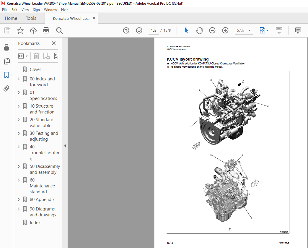
KCCV layout drawing 10-16
KCCV ventilator 10-19
KDOC muffler 10-23
Damper 10-25
Cooling system 10-26
Cooling system hydraulic piping diagram 10-27
Cooling fan motor 10-28
Power train 10-37
Power train 10-37
Power train system diagram 10-38
Drive shaft 10-40
HST hydraulic piping diagram 10-41
HST pump 10-42
HST motor 10-50
Transfer 10-56
Clutch solenoid valve 10-62
Axle 10-63
Differential 10-65
Torque proportioning differential 10-68
00 Index and foreword
Index
WA200-7 00-3
Limited slip differential 10-69
Final drive 10-72
Steering system 10-75
Steering piping diagram 10-75
Orbitrol valve 10-76
Steering column 10-84
Priority valve 10-85
Emergency steering valve 10-88
Brake system 10-91
Brake piping diagram 10-91
Brake valve 10-92
Charge valve 10-96
Accumulator (for brake) 10-100
Slack adjuster 10-101
Brake 10-103
Parking brake control 10-106
Parking brake 10-107
Parking brake cylinder 10-108
Parking brake solenoid valve 10-109
Inching valve 10-111
Undercarriage and frame 10-112
Axle mount and center hinge pin 10-112
Hydraulic system 10-114
Hydraulic component layout 10-114
Work equipment control lever linkage 10-116
Hydraulic tank 10-117
Accumulator (for PPC circuit) 10-119
Work equipment control valve 10-120
PPC valve 10-133
Attachment EPC valve 10-139
Work equipment lock solenoid valve 10-140
ECSS valve 10-141
Accumulator (for ECSS) 10-143
2-way restrictor valve 10-144
Cushion valve 10-145
Accumulator (for oil cooler circuit) 10-146
Quadruple gear pump 10-147
Quick coupler solenoid valve 10-148
Work equipment 10-149
Work equipment linkage 10-149
Bucket 10-151
Bucket positioner and boom kick-out 10-152
Cab and its attachments 10-158
Cab 10-158
Electrical system 10-159
Machine monitor system 10-159
Machine monitor 10-164
Electrical system (HST controller system) 10-186
System component parts 10-202
HST controller 10-208
ECSS 10-212
KOMTRAX system 10-214
Engine starting circuit 10-217
Engine stopping circuit 10-219
Preheating system 10-220
Automatic preheating system 10-221
00 Index and foreword
Index
00-4 WA200-7
Manual preheating system 10-221
Engine output limit function 10-222
Automatic warm-up function 10-222
Parking brake control system 10-223
Multi-function mono-lever 10-227
Sensor 10-229
20 Standard value table
Standard value table 20-3
Standard value table for engine 20-3
Standard value table for machine 20-5
30 Testing and adjusting
Related information on testing and adjusting 30-4
Tools for testing and adjusting 30-4
Engine and cooling system 30-7
Testing and adjusting engine speed 30-7
Testing exhaust gas temperature 30-9
Testing exhaust gas color 30-10
Testing and adjusting valve clearance 30-12
Testing compression pressure 30-14
Testing blowby pressure 30-17
Testing engine oil pressure 30-18
Testing boost pressure 30-19
Handling equipment of fuel system devices 30-21
Releasing remaining pressure from fuel system 30-21
Testing fuel pressure 30-22
Testing fuel discharge, return and leakage 30-27
Bleeding air from fuel system 30-32
Testing fuel circuit for leakage 30-34
Handling cylinder cutout mode operation 30-35
Handling no-injection cranking operation 30-35
Testing KDPF and muffler stack for looseness and damage 30-36
Testing KDOC function 30-36
Testing installed condition of cylinder heads and manifolds 30-37
Testing engine piping for damage and looseness 30-37
Testing and adjusting air conditioner compressor belt tension 30-38
Testing and replacing alternator belt 30-39
Testing and replacing auto-tensioner 30-41
Power train 30-43
Testing oil leakage from axle final drive 30-43
Testing drive shaft for looseness, backlash, and damage 30-44
Testing accelerator pedal 30-45
Testing and adjusting HST oil pressure 30-47
Testing transfer clutch control pressure 30-52
Steering system 30-53
Testing directional lever 30-53
Testing and adjusting steering wheel 30-54
Testing work equipment control lever 30-56
Testing and adjusting steering circuit oil pressure 30-57
Bleeding air from steering circuit 30-59
Brake system 30-60
Testing brake pedal 30-60
Testing and adjusting brake pedal and linkage 30-61
00 Index and foreword
Index
WA200-7 00-5
Testing braking performance 30-62
Testing and adjusting accumulator charge pressure 30-63
Testing wheel brake oil pressure 30-65
Testing lowering of wheel brake pressure 30-66
Testing wear of wheel brake disc 30-69
Bleeding air from wheel brake circuit 30-70
Releasing remaining pressure in brake accumulator circuit 30-71
Testing parking brake performance 30-72
Testing parking brake release pressure 30-73
Method of releasing parking brake manually 30-74
Hydraulic system 30-75
Testing and adjusting cooling fan speed 30-75
Testing cooling fan pump circuit oil pressure 30-76
Testing work equipment PPC oil pressure 30-77
Testing and adjusting work equipment oil pressure 30-78
Bleeding air from each part 30-79
Releasing remaining pressure in hydraulic circuit 30-80
Work equipment 30-81
Testing and adjusting bucket positioner 30-81
Testing and adjusting boom kick-out switch 30-82
Checking the proximity switch working pilot lamp 30-83
Electrical system 30-85
Adjusting replaced, reassembled or added sensor, controller, etc with machine monitor 30-85
Special functions of machine monitor 30-87
KOMTRAX terminal start-up procedure 30-141
Lamp indication of KOMTRAX terminal 30-144
Handling voltage circuit of controller 30-148
Test diodes 30-149
Pm Clinic 30-150
Pm Clinic service 30-150
40 Troubleshooting
Related information on troubleshooting 40-9
Points to remember when performing troubleshooting 40-9
How to proceed in troubleshooting 40-11
Checks before troubleshooting 40-13
Check procedure before troubleshooting 40-15
Preparation for troubleshooting of electrical system 40-33
Classification and procedures of troubleshooting 40-38
Symptom and troubleshooting No 40-42
Information described in troubleshooting table 40-44
Procedure for troubleshooting of open circuit in wiring harness of pressure sensor system 40-46
Connector list and layout 40-48
Connection table of connector by No of pins 40-61
T-box and T-adapter list 40-98
Fuse location table 40-102
Failure code list 40-105
Troubleshooting by failure code (Display of code) 40-113
Failure code [2F00MB] Malfunction of Parking Brake 40-113
Failure code [2G42ZG] Accumulator Oil Pressure Low (Front) 40-115
Failure code [2G43ZG] Accumulator Oil Pressure Low (Rear) 40-117
Failure code [6091NX] HST Filter Clogging 40-119
Failure code [7RHYKA] Open Circuit of Fan Motor EPC Solenoid Output 40-121
Failure code [7RHYKB] Ground Fault of Fan Motor EPC Solenoid Output 40-123
Failure code [7RHYKY] Hot Short of Fan Motor EPC Solenoid Output 40-125
00 Index and foreword
Index
00-6 WA200-7
Failure code [989FN1] Travel Speed Overrun Alarm 40-127
Failure code [AB00L6] Discharge of Alternator R Terminal 40-128
Failure code [AB00MA] Ground Fault or Open Circuit of Battery Relay Status Signal Line, or Insufficient
Battery Charging 40-130
Failure code [B@BAZG] Engine Oil Pressure Low 40-132
Failure code [B@BCNS] Engine Water Overheat 40-133
Failure code [B@BCZK] Engine Coolant Level Low 40-134
Failure code [B@C6NS] Front Brake Oil Temperature Overheat (This Alarm) 40-136
Failure code [B@CRNS] HST Oil Temperature Overheat 40-137
Failure code [CA115] Eng Ne and Bkup Speed Sens Error 40-138
Failure code [CA122] Charge Air Pressure Sensor High Error 40-139
Failure code [CA123] Charge Air Pressure Sensor Low Error 40-141
Failure code [CA131] Throttle Sensor High Error 40-143
Failure code [CA132] Throttle Sensor Low Error 40-145
Failure code [CA144] Coolant Temperature Sensor High Error 40-147
Failure code [CA145] Coolant Temperature Sensor Low Error 40-149
Failure code [CA153] Charge Air Temperature Sensor High Error 40-151
Failure code [CA154] Chg Air Temp Sensor Low Error 40-153
Failure code [CA187] Sensor 2 Supply Voltage Low Error 40-155
Failure code [CA221] Ambient Pressure Sensor High Error 40-157
Failure code [CA222] Ambient Pressure Sensor Low Error 40-159
Failure code [CA227] Sensor 2 Supply Voltage High Error 40-161
Failure code [CA234] Engine Overspeed 40-162
Failure code [CA238] Ne Speed Sensor Supply Volt Error 40-163
Failure code [CA239] Ne Speed Sens Supply Volt High Error 40-164
Failure code [CA271] IMV/PCV1 Short Error 40-165
Failure code [CA272] IMV/PCV1 Open Error 40-167
Failure code [CA295] Ambient Press Sens In Range Error 40-169
Failure code [CA322] Injector #1 (L#1) Open/Short Error 40-170
Failure code [CA324] Injector #3 (L#3) Open/Short Error 40-172
Failure code [CA331] Injector #2 (L#2) Open/Short Error 40-174
Failure code [CA332] Injector #4 (L#4) Open/Short Error 40-176
Failure code [CA343] Engine Controller Internal Failure 40-178
Failure code [CA351] Injectors Drive Circuit Error 40-179
Failure code [CA352] Sensor 1 Supply Voltage Low Error 40-180
Failure code [CA356] Mass Air Flow Sensor High Error 40-182
Failure code [CA357] Mass Air Flow Sensor Low Error 40-184
Failure code [CA386] Sensor 1 Supply Voltage High Error 40-186
Failure code [CA428] Water in Fuel Sensor High Error 40-187
Failure code [CA429] Water in Fuel Sensor Low Error 40-189
Failure code [CA431] Idle Validation Sw Error 40-191
Failure code [CA432] Idle Validation Process Error 40-194
Failure code [CA435] Engine Oil Pressure Sw Error 40-196
Failure code [CA441] Battery Voltage Low Error 40-197
Failure code [CA442] Battery Voltage High Error 40-199
Failure code [CA449] Rail Press Very High Error 40-200
Failure code [CA451] Common Rail Pressure Sensor High Error 40-201
Failure code [CA452] Common Rail Pressure Sensor Low Error 40-203
Failure code [CA466] KVGT Motor Driver Position Error 40-205
Failure code [CA488] Chg Air Temp High Torque Derate 40-207
Failure code [CA515] Rail Pressure Sensor Sup Volt High Error 40-208
Failure code [CA516] Rail Pressure Sensor Sup Volt Low Error 40-210
Failure code [CA553] Common Rail Pressure High Error 1 40-212
Failure code [CA555] Crankcase Press High Error 1 40-213
Failure code [CA556] Crankcase Press High Error 2 40-214
Failure code [CA559] Rail Press Low Error 1 40-215
00 Index and foreword
Index
WA200-7 00-7
Failure code [CA689] Engine Ne Speed Sensor Error 40-218
Failure code [CA691] Intake Air Temp Sens High Error 40-220
Failure code [CA692] Intake Air Temp Sens Low Error 40-222
Failure code [CA697] ECM Internal Temperature Sensor High Error 40-224
Failure code [CA698] EMC Internal Temperature Sensor Low Error 40-225
Failure code [CA731] Engine Bkup Speed Sensor Phase Error 40-226
Failure code [CA778] Engine Bkup Speed Sensor Error 40-228
Failure code [CA1117] Persistent Data Lost Error 40-233
Failure code [CA1695] Sensor 5 Supply Voltage High Error 40-234
Failure code [CA1696] Sensor 5 Supply Voltage Low Error 40-235
Failure code [CA1843] Crankcase Press Sens High Error 40-236
Failure code [CA1844] Crankcase Press Sens Low Error 40-238
Failure code [CA1896] EGR Valve Stuck Error 40-240
Failure code [CA1942] Crankcase Press Sens In-Range Error 40-241
Failure code [CA1961] EGR Motor Driver IC Over Temp Error 40-242
Failure code [CA2185] Throttle Sensor Supply Voltage High Error 40-243
Failure code [CA2186] Throttle Sensor Supply Voltage Low Error 40-245
Failure code [CA2249] Rail Press Low Error 2 40-247
Failure code [CA2272] EGR Valve Position Sensor Low Error 40-248
Failure code [CA2311] IMV Solenoid Error 40-250
Failure code [CA2349] EGR Valve Solenoid Open Circuit Error 40-251
Failure code [CA2353] EGR Valve Solenoid Short Circuit Error 40-253
Failure code [CA2357] EGR Valve Servo Error 40-255
Failure code [CA2373] Exhaust Manifold Pressure Sensor High Error 40-256
Failure code [CA2374] Exhaust Manifold Pressure Sensor Low Error 40-258
Failure code [CA2375] EGR Orifice Temperature Sensor High Error 40-260
Failure code [CA2376] EGR Orifice Temperature Sensor Low Error 40-262
Failure code [CA2554] Exhaust Manifold Pressure Sensor In-Range Error 40-264
Failure code [CA2555] Grid Heater Relay Voltage Low Error 40-265
Failure code [CA2556] Grid Heater Relay Voltage High Error 40-267
Failure code [CA2961] EGR Orifice Temperature High Error 1 40-269
Failure code [CA2973] Charge Air Pressure Sensor In-Range Error 40-270
Failure code [CA3419] Mass Air Flow Sensor Sup Volt High Error 40-271
Failure code [CA3421] Mass Air Flow Sensor Sup Volt Low Error 40-273
Failure code [CA3724] EGR/KVGT Motor Driver Power Low Error 40-275
Failure code [CA3741] Common Rail Pressure Valve Trip Error 40-277
Failure code [CA3918] KVGT Stuck Error 40-278
Failure code [CA3919] KVGT Motor Driver IC Over Temperature Error 40-279
Failure code [CA3921] KVGT Servo Error 2 40-280
Failure code [CA3922] KVGT Motor Driver Open Error 40-281
Failure code [CA3923] KVGT Motor Driver Short Error 40-283
Failure code [D110L4] Disconnection or Short to Ground of Battery Relay Signal Line 40-285
Failure code [D160KA] Disconnection of Backup Lamp Relay Output 40-287
Failure code [D160KB] Ground Fault of Backup Lamp Relay Output 40-289
Failure code [D160KY] Hot Short of Backup Lamp Relay Output 40-291
Failure code [D191KA] Disconnection of Neutral Output Relay 40-293
Failure code [D191KB] Ground Fault of Neutral Output Relay 40-295
Failure code [D191KY] Hot Short of Neutral Output Relay 40-297
Failure code [D192KA] Disconnection of ECSS Solenoid Relay 40-299
Failure code [D192KB] Ground Fault of ECSS Solenoid Relay 40-301
Failure code [D192KY] Hot Short of ECSS Solenoid Relay 40-303
Failure code [D1B0KA] Disconnection of HST Safety Relay 40-305
Failure code [D1B0KB] Ground Fault of HST Safety Relay 40-307
Failure code [D1B0KY] Hot Short of HST Safety Relay 40-309
Failure code [D1B0MC] Malfunction of HST Safety Relay 40-311
Failure code [D1E6KA] Disconnection of Parking Brake Relay 40-312
00 Index and foreword
Index
00-8 WA200-7
Failure code [D1E6KB] Ground Fault of Parking Brake Relay 40-314
Failure code [D1E6KY] Hot Short of Parking Brake Relay 40-316
Failure code [D5ZHKA] Failure of Key SW C Signal 40-318
Failure code [D5ZHKB] Key SW C Signal Hot Short Circuit 40-320
Failure code [D5ZHL6] Disconnection of Key SW C 40-322
Failure code [DAF3KK] Controller Power Source Low (MON) 40-324
Failure code [DAF5KP] 5 V Sensor Power Supply: Ground Fault 40-326
Failure code [DAF6KP] 24 V Sensor Power Supply: Ground Fault 40-328
Failure code [DAFRKR] Machine Monitor CAN2 Communication Error (Machine Monitor) 40-330
Failure code [DAJ0KK] Controller Power Source Low (HST) 40-331
Failure code [DAJ0KT] Abnormality of Non-volatile Memory (HST) 40-334
Failure code [DAJ0MC] HST Controller Malfunction 40-335
Failure code [DAJ1KA] Disconnection of Key SW ACC (HST) 40-336
Failure code [DAJ2KK] Solenoid Power Source Low (HST) 40-338
Failure code [DAJ4KB] Ground Fault of Solenoid Self-Holding Relay (HST) 40-341
Failure code [DAJ4KZ] Failure of Solenoid Self-Holding Relay (HST) 40-343
Failure code [DAJ5KX] Failure of 5 V Power Source 0 (HST) 40-345
Failure code [DAJ6KX] Failure of 5 V Power Source 1 (HST) 40-347
Failure code [DAJ9KQ] Inconsistency of Model Selection (HST) 40-349
Failure code [DAJLKA] Operating Lamp Open Circuit (HST) 40-350
Failure code [DAJLKB] Operating Lamp Short Circuit (HST) 40-352
Failure code [DAJQKR] CAN2 Disconnection (HST) 40-354
Failure code [DAJRMA] Inconsistency of Option Selection (HST) 40-355
Failure code [DB2QKR] CAN2 Disconnection (Engine Controller) 40-356
Failure code [DB2RKR] CAN1 Disconnection (Engine Controller) 40-360
Failure code [DBE6KX] 24V Output Power Supply System Failure 40-363
Failure code [DD1NL4] Fan Auto Reverse Switch Signal Error 40-365
Failure code [DD1NLD] Fan Reverse Switch Signal: Abnormal 40-367
Failure code [DDB6L4] Parking Brake Signal Malfunction 40-369
Failure code [DDD7KA] Failure of Variable Speed Control 40-371
Failure code [DDD7KY] Hot Short of Variable Speed Control 40-373
Failure code [DDE5MA] Disconnection of Steering Oil Pressure Switch (Emergency Steering Control
Switch) 40-375
Failure code [DDK3KA] FNR SW Input Signal Disconnection 40-377
Failure code [DDK3KB] FNR SW Input Signal Short Circuit 40-379
Failure code [DDK6KA] FNR Lever Input Signal Disconnection 40-381
Failure code [DDK6KY] FNR Lever Input Signal Disconnection (Hot Short) 40-383
Failure code [DDNRLD] Ground Fault of Work Equipment Lock Switch 40-385
Failure code [DDS5L6] Low Steering Oil Pressure (Emergency Steering Control) 40-387
Failure code [DF10KA] Disconnection of Speed Range Input Switch 40-389
Failure code [DF10KB] Disconnection of Speed Range Selector Switch (Hot Short) 40-394
Failure code [DGH1KX] HST Oil Temperature Sensor Short to Ground 40-399
Failure code [DGR2KB] Ground Fault of Brake Oil Temperature Sensor 40-401
Failure code [DGR2KZ] Failure of Brake Oil Temperature Sensor 40-403
Failure code [DHH1KX] Failure of HST Oil Pressure Sensor 40-405
Failure code [DHH1KY] Hot Short of HST Oil Pressure Sensor 40-407
Failure code [DHPCKX] Failure of Boom Pressure Sensor (Bottom) 40-409
Failure code [DHPDKX] Failure of Boom Pressure Sensor (Head) 40-411
Failure code [DHTCL6] HST Oil Filter Clogging Detection Failure 40-413
Failure code [DJF1KA] Disconnection or Hot Short Circuit of Fuel Level Sensor 40-415
Failure code [DK5DKA] Failure of 3rd Lever Potentiometer Sensor (Main) 40-417
Failure code [DK5DKY] Hot Short of 3rd Lever Potentiometer Sensor (Main) 40-420
Failure code [DK5DL8] 3rd Lever Potentiometer Sensor (Main & Sub) Disagree 40-422
Failure code [DK5EKA] Failure of 3rd Lever Potentiometer Sensor (Sub) 40-425
Failure code [DK5EKY] Hot Short of 3rd Lever Potentiometer Sensor (Sub) 40-428
Failure code [DKA0KX] Failure of Boom Angle Sensor 40-430
00 Index and foreword
Index
WA200-7 00-9
Failure code [DLM3KA] Failure of Cooling Fan Speed Sensor 40-432
Failure code [DLM3LC] Ground Fault of Cooling Fan Speed Sensor 40-434
Failure code [DLT3KX] Vehicle Speed Sensor Circuit Failure (B) 40-435
Failure code [DLT4KX] Vehicle Speed Sensor Circuit Failure (A) 40-437
Failure code [DLT4L0] Vehicle Speed Sensor Failure (A & B) 40-439
Failure code [DLT4LC] Vehicle Speed Sensor Failure (A or B) 40-442
Failure code [DT22KB] Ground Fault of Work Equip Lock Indicator 40-444
Failure code [DV00KY] Hot Short of Alarm Buzzer 40-446
Failure code [DW26KA] Open Circuit of Motor 2 Solenoid 40-448
Failure code [DW26KB] Ground Fault of Motor 2 Solenoid 40-450
Failure code [DW26KY] Hot Short of Motor 2 Solenoid 40-452
Failure code [DW44KA] Open Circuit of Directional Pressure Selection Solenoid 40-454
Failure code [DW44KB] Ground Fault of Directional Pressure Selection Solenoid 40-456
Failure code [DW44KY] Hot Short of Directional Pressure Selection Solenoid 40-458
Failure code [DWM1KA] Disconnection of Neutral Lock Solenoid 40-460
Failure code [DWM1KB] Ground Fault of Neutral Lock Solenoid 40-462
Failure code [DWM1KY] Hot Short of Neutral Lock Solenoid 40-464
Failure code [DX19KA] Disconnection of Motor 1 Solenoid 40-466
Failure code [DX19KB] Ground Fault of Motor 1 Solenoid 40-469
Failure code [DX19KY] Hot Short of Motor 1 Solenoid 40-471
Failure code [DX20KA] Disconnection of Clutch EPC Solenoid 40-473
Failure code [DX20KB] Ground Fault of Clutch EPC Solenoid 40-476
Failure code [DX20KY] Hot Short of Clutch EPC Solenoid 40-478
Failure code [DXH7KA] Disconnection of Reverse Solenoid 40-480
Failure code [DXH7KB] Ground Fault of Reverse Solenoid 40-482
Failure code [DXH7KY] Hot Short of Reverse Solenoid 40-484
Failure code [DXH8KA] Disconnection of Forward Solenoid 40-485
Failure code [DXH8KB] Ground Fault of Forward Solenoid 40-487
Failure code [DXH8KY] Hot Short of Forward Solenoid 40-489
Failure code [DXHJKA] Disconnection of 3rd EPC Solenoid (EXT) 40-490
Failure code [DXHJKB] Ground Fault of 3rd EPC Solenoid (EXT) 40-492
Failure code [DXHJKY] Hot Short of 3rd EPC Solenoid (EXT) 40-494
Failure code [DXHKKA] Disconnection of 3rd EPC Solenoid (RET) 40-495
Failure code [DXHKKB] Ground Fault of 3rd EPC Solenoid (RET) 40-497
Failure code [DXHKKY] Hot Short of 3rd EPC Solenoid (RET) 40-499
Failure code [H2K0KA] Failure of Quick Coupler Lock Signal 40-500
Failure code [H2K0KY] Hot Short of Quick Coupler Lock Signal 40-503
Failure code [J141N1] Steering Pump Over Run 40-505
Failure code [LA00L3] Failure of Fan Reverse 40-506
Failure code [M100N1] HST Pump Over Run 40-507
Failure code [M400N1] HST Motor 1 Over Run 40-508
Troubleshooting of electrical system (E-mode) 40-509
E-1 Engine does not start 40-509
E-2 Manual preheating system does not work 40-514
E-3 Automatic preheating system does not work 40-517
E-4 While preheating is working, preheating monitor does not light up 40-519
E-5 When starting switch is turned to ON position, nothing is displayed on machine monitor 40-521
E-6 Travel speed is slow 40-524
E-7 ECSS does not operate 40-526
E-8 ECSS remains being operated 40-529
E-9 Boom kick-out does not work or is not reset 40-532
E-10 Bucket positioner does not work or is not reset 40-535
E-11 Boom FLOAT holding does not work or is not reset 40-538
E-12 Directional selection does not work normally 40-541
E-13 Fan does not rotate in reverse 40-552
E-14 Fan remains in reverse rotation mode 40-555
00 Index and foreword
Index
00-10 WA200-7
E-15 Wipers do not operate 40-557
E-16 Window washer does not operate 40-562
E-17 Headlamp, clearance lamp, tail lamp or license-plate lamp does not light up or does not go out
40-565
E-18 Working lamp does not light up or does not go out 40-574
E-19 Turn signal and hazard lamp do not light up or do not go out 40-579
E-20 Stop lamp does not light up or remains lighting up 40-586
E-21 Backup lamp does not light up or remains lighting up 40-589
E-22 Backup alarm does not sound or does not stop sounding 40-592
E-23 Horn does not sound or does not stop sounding 40-594
E-24 Alarm buzzer does not sound or does not stop sounding 40-597
E-25 KOMTRAX system does not operate normally 40-599
E-26 Fuel gauge does not indicate correct level 40-601
E-27 Seat belt caution lamp indication is incorrect 40-603
Troubleshooting for hydraulic and mechanical system (H-mode) 40-605
Information described in troubleshooting table (H-mode) 40-605
System chart of hydraulic and mechanical systems 40-606
Failure mode and cause table 40-608
H-1 Machine travels neither forward nor in reverse 40-614
H-2 Machine does not travel forward (normally travels in reverse) 40-616
H-3 Machine does not travel in reverse (normally travels forward) 40-617
H-4 Both forward and reverse travel speeds are low 40-618
H-5 Forward travel speed is low (normal when traveling in reverse) 40-620
H-6 Reverse travel speed is low (normal when traveling forward) 40-621
H-7 Machine lacks power when traveling both forward and in reverse 40-622
H-8 Machine lacks power when traveling forward (normal when traveling in reverse) 40-624
H-9 Machine lacks power when traveling in reverse (normal when traveling forward) 40-625
H-10 Engine stalls during travel or engine speed drops significantly 40-626
H-11 Machine does not turn 40-627
H-12 Steering wheel is heavy to turn 40-629
H-13 Machine sways or large shocks are made while machine turns 40-630
H-14 Machine turns to either side unintentionally during traveling 40-631
H-15 Brake does not work or it is weak 40-632
H-16 Brake is not released or drags 40-633
H-17 Parking brake does not work or it is weak 40-634
H-18 Parking brake is not released or drags 40-635
H-19 Boom does not rise 40-636
H-20 Boom moves slow or lacks lifting force 40-637
H-21 Boom rising speed lowers at certain height 40-638
H-22 Lift cylinder cannot hold down bucket (bucket rises off ground) 40-639
H-23 Hydraulic drift of boom is large 40-640
H-24 Boom wobbles during operation 40-644
H-25 Bucket does not tilt back 40-645
H-26 Bucket moves slow or lacks tilting back force 40-646
H-27 Bucket speed lowers in tilt-back motion 40-647
H-28 Bucket cylinder cannot hold down bucket (bucket rises off ground) 40-648
H-29 Hydraulic drift of bucket is large 40-649
H-30 Loaded bucket wobbles during travel (with work equipment valve at “HOLD”) 40-650
H-31 Boom and bucket control levers do not move smoothly and are heavy to move 40-651
H-32 Engine speed lowers remarkably or engine stalls while work equipment is operated 40-652
H-33 Large shock is made when work equipment starts and stops 40-653
H-34 When certain work equipment is relieved hydraulically, other work equipment moves 40-654
H-35 ECSS does not operate and machine pitches and bounds 40-655
H-36 Fan speed is abnormal (too high or low, or fan does not rotate) 40-656
H-37 Unusual noise is heard from around fan 40-658
Troubleshooting of engine (S-mode) 40-659
00 Index and foreword
Index
WA200-7 00-11
Information mentioned in troubleshooting table (S mode) 40-659
S-1 Engine does not crank when starting switch is turned to START position 40-660
S-2 Engine cranks but no exhaust smoke comes out 40-661
S-3 Fuel is being injected but engine does not start (misfiring: engine cranks but does not start) 40-662
S-4 Engine startability is poor 40-663
S-5 Engine does not pick up smoothly 40-665
S-6 Engine stops during operation 40-667
S-7 Engine runs rough or is unstable 40-668
S-8 Engine lacks power 40-669
S-9 Exhaust smoke is black 40-671
S-10 Engine oil consumption is excessive 40-673
S-11 Oil becomes contaminated quickly 40-674
S-12 Fuel consumption is excessive 40-675
S-13 Oil is in coolant (or coolant spurts or coolant level goes down) 40-676
S-14 Oil pressure drops 40-677
S-15 Fuel mixes into engine oil 40-678
S-16 Water mixes into engine oil (milky) 40-679
S-17 Coolant temperature rises too high (overheating) 40-680
S-18 Unusual noise is heard 40-681
S-19 Vibration is excessive 40-682
S-20 Air cannot be bled from fuel circuit 40-683
50 Disassembly and assembly
General information on disassembly and assembly 50-4
How to read this manual 50-4
Coating materials list 50-6
Special tool list 50-10
Sketches of special tools 50-14
Engine and cooling system 50-24
Removal and installation of fuel supply pump assembly 50-24
Removal and installation of fuel injector assembly 50-28
Removal and installation of engine hood assembly 50-36
Removal and installation of cylinder head assembly 50-39
Removal and installation of radiator assembly 50-50
Removal and installation of air aftercooler assembly 50-53
Removal and installation of hydraulic oil cooler assembly 50-55
Removal and installation of engine assembly 50-57
Removal and installation of belt for alternator and air conditioner compressor 50-62
Removal and installation of engine front oil seal assembly 50-64
Removal and installation of engine rear oil seal assembly 50-68
Removal and installation of cooling fan and fan motor assembly 50-72
Removal and installation of fuel tank assembly 50-75
Removal and installation of KCCV ventilator assembly 50-77
Removal and installation of KDOC muffler 50-78
Removal and installation of EGR cooler assembly 50-79
Removal and installation of EGR valve assembly 50-81
Power train 50-83
Removal and installation of transfer assembly 50-83
Disassembly and assembly of transfer assembly 50-87
Removal and installation of parking brake assembly 50-110
Removal and installation of parking brake cylinder assembly 50-112
Disassembly and assembly of parking brake assembly 50-113
Removal and installation of front axle assembly 50-119
Removal and installation of rear axle assembly 50-121
Disassembly and assembly of axle housing assembly 50-124
00 Index and foreword
Index
00-12 WA200-7
Disassembly and assembly of differential assembly 50-133
Undercarriage and frame 50-158
Removal and installation of center hinge pin 50-158
Removal and installation of counterweight assembly 50-167
Hydraulic system 50-170
Removal and installation of HST pump and quadruple type gear pump assembly 50-170
Removal and installation of HST motor 1 assembly 50-174
Removal and installation of HST motor 2 assembly 50-176
Removal and installation of work equipment control valve assembly 50-179
Removal and installation of ECSS (Electronically Controlled Suspension System) valve assembly
50-181
Removal and installation of hydraulic tank assembly 50-183
Disassembly and assembly of hydraulic cylinder assembly 50-185
Work equipment 50-189
Removal and installation of work equipment assembly 50-189
Cab and its attachments 50-195
Removal and installation of operator’s cab and floor frame assembly 50-195
Removal and installation of operator’s cab glass (adhered glass) 50-200
Disassembly and assembly of operator’s seat 50-208
Removal and installation of air conditioner unit assembly 50-218
Removal and installation of air conditioner compressor assembly 50-224
Electrical system 50-226
Removal and installation of machine monitor 50-226
Removal and installation of engine controller assembly 50-228
Removal and installation of HST controller assembly 50-230
Removal and installation of KOMTRAX terminal assembly 50-231
60 Maintenance standard
Engine and cooling system 60-3
Engine mount and transfer mount 60-3
Damper 60-4
Cooling system 60-5
Cooling fan motor 60-6
Power train 60-8
Drive shaft 60-8
Transfer 60-9
Axle 60-17
Differential 60-19
Limited slip differential 60-23
Final drive 60-25
Steering system 60-28
Orbitrol valve 60-28
Steering cylinder 60-29
Steering column 60-32
Priority valve 60-33
Emergency steering valve 60-34
Brake system 60-36
Charge valve 60-36
Slack adjuster 60-38
Brake 60-39
Parking brake 60-41
Undercarriage and frame 60-42
Axle mount and center hinge pin 60-42
Hydraulic system 60-46
Hydraulic tank 60-46
00 Index and foreword
Index
WA200-7 00-13
Work equipment control valve 60-47
PPC valve 60-53
ECSS valve 60-56
Quadruple gear pump 60-57
Work equipment 60-59
Work equipment linkage 60-59
Bucket 60-61
Bucket positioner and boom kick-out 60-62
Work equipment cylinder 60-63
80 Appendix
Air conditioner 80-3
Precautions for refrigerant 80-3
Air conditioner component 80-4
Configuration and function of refrigeration cycle 80-6
Outline of refrigeration cycle 80-7
Air conditioner unit 80-9
Functions of main components in air conditioner unit 80-10
Blower and intake unit 80-11
Compressor 80-12
Condenser 80-13
Receiver drier 80-14
Air conditioner control panel 80-15
Procedure for troubleshooting 80-16
Circuit diagram and arrangement of connector pins 80-18
System diagram 80-20
Details of air conditioner unit 80-22
Parts and connectors layout 80-23
Inspection by self-diagnosis function (displays diagnosis on the control panel) 80-25
Testing temperature control system 80-26
Testing FRESH/RECIRC air changeover 80-27
Testing evaporator temperature sensor 80-29
Testing relays 80-30
Troubleshooting chart 1 80-31
Troubleshooting chart 2 80-33
Information described in troubleshooting table 80-36
Troubleshooting for power supply system (Air conditioner does not operate) 80-37
Troubleshooting for compressor and refrigerant system (Air is not cooled) 80-41
Troubleshooting for blower motor system (No air comes out or air flow is abnormal) 80-44
Troubleshooting for temperature control 80-47
Troubleshooting for FRESH/RECIRC air changeover 80-50
Connection of service tool 80-52
Troubleshooting by gauge pressure 80-54
Precautions for disconnecting and connecting hoses and tubes in air conditioner circuit 80-57
Handling of compressor oil 80-59
90 Diagrams and drawings
Hydraulic diagrams and drawings 90-3
Symbols used in hydraulic circuit diagrams 90-3
Hydraulic circuit diagram 90-5
Electrical diagrams and drawings 90-7
Symbols used in electric circuit diagrams 90-7
Electrical circuit diagram 90-11
Index 1
IMAGES PREVIEW OF THE MANUAL:

More products