$45
Komatsu WA200-7 Wheel Loader Shop Manual SEN06503-10 – PDF DOWNLOAD
Komatsu WA200-7 Wheel Loader Shop Manual SEN06503-10 – PDF DOWNLOAD
FILE DETAILS:
Komatsu WA200-7 Wheel Loader Shop Manual SEN06503-10 – PDF DOWNLOAD
Language : English
Pages : 1580
Downloadable : Yes
File Type : PDF
Size: 123 MB
TABLE OF CONTENTS:
Komatsu WA200-7 Wheel Loader Shop Manual SEN06503-10 – PDF DOWNLOAD
Cover 1
00 Index and foreword 3
Index and foreword 4
Index 4
Important safety notice 16
How to read the shop manual 23
Explanation of terms for maintenance standard 25
Handling equipment of fuel system devices 27
Handling of intake system parts 28
Handling of hydraulic equipment 29
Method of disconnecting and connecting of push-pull type coupler 31
Handling of electrical equipment 34
How to read electric wire code 42
Precautions when performing operation 45
Practical use of KOMTRAX 50
Standard tightening torque table 51
List of Abbreviation 57
Conversion table 61
01 Specifications 67
Specifications 70
Specification dimension drawing 70
Specifications 72
Weight table 80
Table of fuel, coolant, and lubricants 84
10 Structure and function 87
Engine and cooling system 90
VFT 90
EGR system piping drawing 94
EGR system circuit diagram 96
EGR valve 98
EGR cooler 100
KCCV layout drawing 102
KCCV ventilator 105
KDOC muffler 109
Damper 111
Cooling system 112
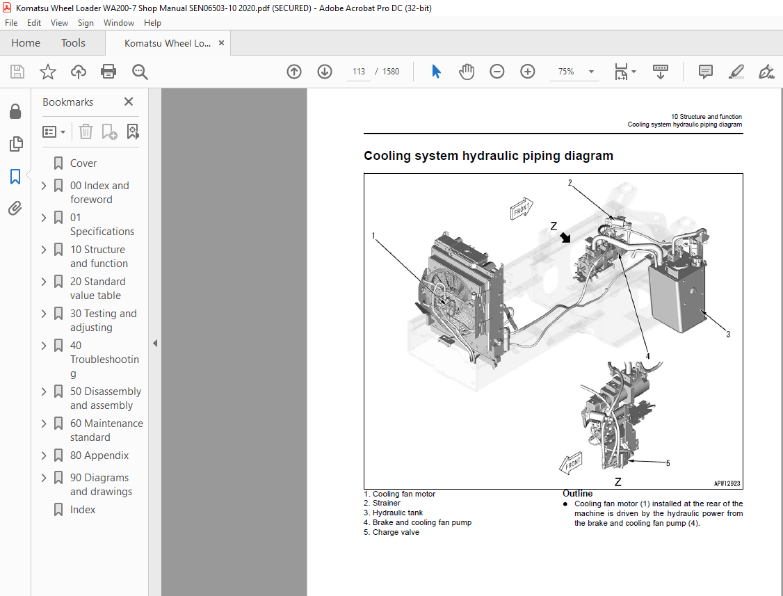
Cooling system hydraulic piping diagram 113
Cooling fan motor 114
Power train 123
Power train 123
Power train system diagram 124
Drive shaft 126
HST hydraulic piping diagram 127
HST pump 128
HST motor 136
Transfer 142
Clutch solenoid valve 148
Axle 149
Differential 151
Torque proportioning differential 154
Limited slip differential 155
Final drive 158
Steering system 161
Steering piping diagram 161
Orbitrol valve 162
Steering column 170
Priority valve 171
Emergency steering valve 174
Brake system 177
Brake piping diagram 177
Brake valve 178
Charge valve 182
Accumulator (for brake) 186
Slack adjuster 187
Brake 189
Parking brake control 192
Parking brake 193
Parking brake cylinder 194
Parking brake solenoid valve 195
Inching valve 197
Undercarriage and frame 198
Axle mount and center hinge pin 198
Hydraulic system 200
Hydraulic component layout 200
Work equipment control lever linkage 202
Hydraulic tank 203
Accumulator (for PPC circuit) 205
Work equipment control valve 206
PPC valve 219
Attachment EPC valve 225
Work equipment lock solenoid valve 226
ECSS valve 227
Accumulator (for ECSS) 229
2-way restrictor valve 230
Cushion valve 231
Accumulator (for oil cooler circuit) 232
Quadruple gear pump 233
Quick coupler solenoid valve 234
Work equipment 235
Work equipment linkage 235
Bucket 237
Bucket positioner and boom kick-out 238
Cab and its attachments 244
Cab 244
Electrical system 245
Machine monitor system 245
Machine monitor 250
Electrical system (HST controller system) 272
System component parts 288
HST controller 294
ECSS 298
KOMTRAX system 300
Engine starting circuit 303
Engine stopping circuit 305
Preheating system 306
Automatic preheating system 307
Manual preheating system 307
Engine output limit function 308
Automatic warm-up function 308
Parking brake control system 309
Multi-function mono-lever 313
Sensor 315
20 Standard value table 331
Standard value table 333
Standard value table for engine 333
Standard value table for machine 335
30 Testing and adjusting 343
Related information on testing and adjusting 346
Tools for testing and adjusting 346
Engine and cooling system 349
Testing and adjusting engine speed 349
Testing exhaust gas temperature 351
Testing exhaust gas color 352
Testing and adjusting valve clearance 354
Testing compression pressure 356
Testing blowby pressure 359
Testing engine oil pressure 360
Testing boost pressure 361
Handling equipment of fuel system devices 363
Releasing remaining pressure from fuel system 363
Testing fuel pressure 364
Testing fuel discharge, return and leakage 369
Bleeding air from fuel system 374
Testing fuel circuit for leakage 376
Handling cylinder cutout mode operation 377
Handling no-injection cranking operation 377
Testing KDPF and muffler stack for looseness and damage 378
Testing KDOC function 378
Testing installed condition of cylinder heads and manifolds 379
Testing engine piping for damage and looseness 379
Testing and adjusting air conditioner compressor belt tension 380
Testing and replacing alternator belt 381
Testing and replacing auto-tensioner 383
Power train 385
Testing oil leakage from axle final drive 385
Testing drive shaft for looseness, backlash, and damage 386
Testing accelerator pedal 387
Testing and adjusting HST oil pressure 389
Testing transfer clutch control pressure 394
Steering system 395
Testing directional lever 395
Testing and adjusting steering wheel 396
Testing work equipment control lever 398
Testing and adjusting steering circuit oil pressure 399
Bleeding air from steering circuit 401
Brake system 402
Testing brake pedal 402
Testing and adjusting brake pedal and linkage 403
Testing braking performance 404
Testing and adjusting accumulator charge pressure 405
Testing wheel brake oil pressure 407
Testing lowering of wheel brake pressure 408
Testing wear of wheel brake disc 411
Bleeding air from wheel brake circuit 412
Releasing remaining pressure in brake accumulator circuit 413
Testing parking brake performance 414
Testing parking brake release pressure 415
Method of releasing parking brake manually 416
Hydraulic system 417
Testing and adjusting cooling fan speed 417
Testing cooling fan pump circuit oil pressure 418
Testing work equipment PPC oil pressure 419
Testing and adjusting work equipment oil pressure 420
Bleeding air from each part 421
Releasing remaining pressure in hydraulic circuit 422
Work equipment 423
Testing and adjusting bucket positioner 423
Testing and adjusting boom kick-out switch 424
Checking the proximity switch working pilot lamp 425
Electrical system 427
Adjusting replaced, reassembled or added sensor, controller, etc with machine monitor 427
Special functions of machine monitor 429
KOMTRAX terminal start-up procedure 483
Lamp indication of KOMTRAX terminal 486
Handling voltage circuit of controller 490
Test diodes 491
Pm Clinic 492
Pm Clinic service 492
40 Troubleshooting 495
Related information on troubleshooting 503
Points to remember when performing troubleshooting 503
How to proceed in troubleshooting 505
Checks before troubleshooting 507
Check procedure before troubleshooting 509
Preparation for troubleshooting of electrical system 527
Classification and procedures of troubleshooting 532
Symptom and troubleshooting No 536
Information described in troubleshooting table 538
Procedure for troubleshooting of open circuit in wiring harness of pressure sensor system 540
Connector list and layout 542
Connection table of connector by No of pins 555
T-box and T-adapter list 592
Fuse location table 596
Failure code list 599
Troubleshooting by failure code (Display of code) 607
Failure code [2F00MB] Malfunction of Parking Brake 607
Failure code [2G42ZG] Accumulator Oil Pressure Low (Front) 609
Failure code [2G43ZG] Accumulator Oil Pressure Low (Rear) 611
Failure code [6091NX] HST Filter Clogging 613
Failure code [7RHYKA] Open Circuit of Fan Motor EPC Solenoid Output 615
Failure code [7RHYKB] Ground Fault of Fan Motor EPC Solenoid Output 617
Failure code [7RHYKY] Hot Short of Fan Motor EPC Solenoid Output 619
Failure code [989FN1] Travel Speed Overrun Alarm 621
Failure code [AB00L6] Discharge of Alternator R Terminal 622
Failure code [AB00MA] Ground Fault or Open Circuit of Battery Relay Status Signal Line, or Insufficient Battery Charging 624
Failure code [B@BAZG] Engine Oil Pressure Low 626
Failure code [B@BCNS] Engine Water Overheat 627
Failure code [B@BCZK] Engine Coolant Level Low 628
Failure code [B@C6NS] Front Brake Oil Temperature Overheat (This Alarm) 630
Failure code [B@CRNS] HST Oil Temperature Overheat 631
Failure code [CA115] Eng Ne and Bkup Speed Sens Error 632
Failure code [CA122] Charge Air Pressure Sensor High Error 633
Failure code [CA123] Charge Air Pressure Sensor Low Error 635
Failure code [CA131] Throttle Sensor High Error 637
Failure code [CA132] Throttle Sensor Low Error 639
Failure code [CA144] Coolant Temperature Sensor High Error 641
Failure code [CA145] Coolant Temperature Sensor Low Error 643
Failure code [CA153] Charge Air Temperature Sensor High Error 645
Failure code [CA154] Chg Air Temp Sensor Low Error 647
Failure code [CA187] Sensor 2 Supply Voltage Low Error 649
Failure code [CA221] Ambient Pressure Sensor High Error 651
Failure code [CA222] Ambient Pressure Sensor Low Error 653
Failure code [CA227] Sensor 2 Supply Voltage High Error 655
Failure code [CA234] Engine Overspeed 656
Failure code [CA238] Ne Speed Sensor Supply Volt Error 657
Failure code [CA239] Ne Speed Sens Supply Volt High Error 658
Failure code [CA271] IMV/PCV1 Short Error 659
Failure code [CA272] IMV/PCV1 Open Error 661
Failure code [CA295] Ambient Press Sens In Range Error 663
Failure code [CA322] Injector #1 (L#1) Open/Short Error 664
Failure code [CA324] Injector #3 (L#3) Open/Short Error 666
Failure code [CA331] Injector #2 (L#2) Open/Short Error 668
Failure code [CA332] Injector #4 (L#4) Open/Short Error 670
Failure code [CA343] Engine Controller Internal Failure 672
Failure code [CA351] Injectors Drive Circuit Error 673
Failure code [CA352] Sensor 1 Supply Voltage Low Error 674
Failure code [CA356] Mass Air Flow Sensor High Error 676
Failure code [CA357] Mass Air Flow Sensor Low Error 678
Failure code [CA386] Sensor 1 Supply Voltage High Error 680
Failure code [CA428] Water in Fuel Sensor High Error 681
Failure code [CA429] Water in Fuel Sensor Low Error 683
Failure code [CA431] Idle Validation Sw Error 685
Failure code [CA432] Idle Validation Process Error 688
Failure code [CA435] Engine Oil Pressure Sw Error 690
Failure code [CA441] Battery Voltage Low Error 691
Failure code [CA442] Battery Voltage High Error 693
Failure code [CA449] Rail Press Very High Error 694
Failure code [CA451] Common Rail Pressure Sensor High Error 695
Failure code [CA452] Common Rail Pressure Sensor Low Error 697
Failure code [CA466] KVGT Motor Driver Position Error 699
Failure code [CA488] Chg Air Temp High Torque Derate 701
Failure code [CA515] Rail Pressure Sensor Sup Volt High Error 702
Failure code [CA516] Rail Pressure Sensor Sup Volt Low Error 704
Failure code [CA553] Common Rail Pressure High Error 1 706
Failure code [CA555] Crankcase Press High Error 1 707
Failure code [CA556] Crankcase Press High Error 2 708
Failure code [CA559] Rail Press Low Error 1 709
Failure code [CA689] Engine Ne Speed Sensor Error 712
Failure code [CA691] Intake Air Temp Sens High Error 714
Failure code [CA692] Intake Air Temp Sens Low Error 716
Failure code [CA697] ECM Internal Temperature Sensor High Error 718
Failure code [CA698] EMC Internal Temperature Sensor Low Error 719
Failure code [CA731] Engine Bkup Speed Sensor Phase Error 720
Failure code [CA778] Engine Bkup Speed Sensor Error 722
Failure code [CA1117] Persistent Data Lost Error 727
Failure code [CA1695] Sensor 5 Supply Voltage High Error 728
Failure code [CA1696] Sensor 5 Supply Voltage Low Error 729
Failure code [CA1843] Crankcase Press Sens High Error 730
Failure code [CA1844] Crankcase Press Sens Low Error 732
Failure code [CA1896] EGR Valve Stuck Error 734
Failure code [CA1942] Crankcase Press Sens In-Range Error 735
Failure code [CA1961] EGR Motor Driver IC Over Temp Error 736
Failure code [CA2185] Throttle Sensor Supply Voltage High Error 737
Failure code [CA2186] Throttle Sensor Supply Voltage Low Error 739
Failure code [CA2249] Rail Press Low Error 2 741
Failure code [CA2272] EGR Valve Position Sensor Low Error 742
Failure code [CA2311] IMV Solenoid Error 744
Failure code [CA2349] EGR Valve Solenoid Open Circuit Error 745
Failure code [CA2353] EGR Valve Solenoid Short Circuit Error 747
Failure code [CA2357] EGR Valve Servo Error 749
Failure code [CA2373] Exhaust Manifold Pressure Sensor High Error 750
Failure code [CA2374] Exhaust Manifold Pressure Sensor Low Error 752
Failure code [CA2375] EGR Orifice Temperature Sensor High Error 754
Failure code [CA2376] EGR Orifice Temperature Sensor Low Error 756
Failure code [CA2554] Exhaust Manifold Pressure Sensor In-Range Error 758
Failure code [CA2555] Grid Heater Relay Voltage Low Error 761
Failure code [CA2556] Grid Heater Relay Voltage High Error 763
Failure code [CA2961] EGR Orifice Temperature High Error 1 765
Failure code [CA2973] Charge Air Pressure Sensor In-Range Error 766
Failure code [CA3419] Mass Air Flow Sensor Sup Volt High Error 767
Failure code [CA3421] Mass Air Flow Sensor Sup Volt Low Error 769
Failure code [CA3724] EGR/KVGT Motor Driver Power Low Error 771
Failure code [CA3741] Common Rail Pressure Valve Trip Error 773
Failure code [CA3918] KVGT Stuck Error 774
Failure code [CA3919] KVGT Motor Driver IC Over Temperature Error 775
Failure code [CA3921] KVGT Servo Error 2 776
Failure code [CA3922] KVGT Motor Driver Open Error 777
Failure code [CA3923] KVGT Motor Driver Short Error 779
Failure code [D110L4] Disconnection or Short to Ground of Battery Relay Signal Line 781
Failure code [D160KA] Disconnection of Backup Lamp Relay Output 783
Failure code [D160KB] Ground Fault of Backup Lamp Relay Output 785
Failure code [D160KY] Hot Short of Backup Lamp Relay Output 787
Failure code [D191KA] Disconnection of Neutral Output Relay 789
Failure code [D191KB] Ground Fault of Neutral Output Relay 791
Failure code [D191KY] Hot Short of Neutral Output Relay 793
Failure code [D192KA] Disconnection of ECSS Solenoid Relay 795
Failure code [D192KB] Ground Fault of ECSS Solenoid Relay 797
Failure code [D192KY] Hot Short of ECSS Solenoid Relay 799
Failure code [D1B0KA] Disconnection of HST Safety Relay 801
Failure code [D1B0KB] Ground Fault of HST Safety Relay 803
Failure code [D1B0KY] Hot Short of HST Safety Relay 805
Failure code [D1B0MC] Malfunction of HST Safety Relay 807
Failure code [D1E6KA] Disconnection of Parking Brake Relay 808
Failure code [D1E6KB] Ground Fault of Parking Brake Relay 810
Failure code [D1E6KY] Hot Short of Parking Brake Relay 812
Failure code [D5ZHKA] Failure of Key SW C Signal 814
Failure code [D5ZHKB] Key SW C Signal Hot Short Circuit 816
Failure code [D5ZHL6] Disconnection of Key SW C 818
Failure code [DAF3KK] Controller Power Source Low (MON) 820
Failure code [DAF5KP] 5 V Sensor Power Supply: Ground Fault 822
Failure code [DAF6KP] 24 V Sensor Power Supply: Ground Fault 824
Failure code [DAFRKR] Machine Monitor CAN2 Communication Error (Machine Monitor) 826
Failure code [DAJ0KK] Controller Power Source Low (HST) 827
Failure code [DAJ0KT] Abnormality of Non-volatile Memory (HST) 830
Failure code [DAJ0MC] HST Controller Malfunction 831
Failure code [DAJ1KA] Disconnection of Key SW ACC (HST) 832
Failure code [DAJ2KK] Solenoid Power Source Low (HST) 834
Failure code [DAJ4KB] Ground Fault of Solenoid Self-Holding Relay (HST) 837
Failure code [DAJ4KZ] Failure of Solenoid Self-Holding Relay (HST) 839
Failure code [DAJ5KX] Failure of 5 V Power Source 0 (HST) 841
Failure code [DAJ6KX] Failure of 5 V Power Source 1 (HST) 843
Failure code [DAJ9KQ] Inconsistency of Model Selection (HST) 845
Failure code [DAJLKA] Operating Lamp Open Circuit (HST) 846
Failure code [DAJLKB] Operating Lamp Short Circuit (HST) 848
Failure code [DAJQKR] CAN2 Disconnection (HST) 850
Failure code [DAJRMA] Inconsistency of Option Selection (HST) 851
Failure code [DB2QKR] CAN2 Disconnection (Engine Controller) 852
Failure code [DB2RKR] CAN1 Disconnection (Engine Controller) 856
Failure code [DBE6KX] 24V Output Power Supply System Failure 859
Failure code [DD1NL4] Fan Auto Reverse Switch Signal Error 861
Failure code [DD1NLD] Fan Reverse Switch Signal: Abnormal 863
Failure code [DDB6L4] Parking Brake Signal Malfunction 865
Failure code [DDD7KA] Failure of Variable Speed Control 867
Failure code [DDD7KY] Hot Short of Variable Speed Control 869
Failure code [DDE5MA] Disconnection of Steering Oil Pressure Switch (Emergency Steering Control Switch) 871
Failure code [DDK3KA] FNR SW Input Signal Disconnection 873
Failure code [DDK3KB] FNR SW Input Signal Short Circuit 875
Failure code [DDK6KA] FNR Lever Input Signal Disconnection 877
Failure code [DDK6KY] FNR Lever Input Signal Disconnection (Hot Short) 879
Failure code [DDNRLD] Ground Fault of Work Equipment Lock Switch 881
Failure code [DDS5L6] Low Steering Oil Pressure (Emergency Steering Control) 883
Failure code [DF10KA] Disconnection of Speed Range Input Switch 885
Failure code [DF10KB] Disconnection of Speed Range Selector Switch (Hot Short) 890
Failure code [DGH1KX] HST Oil Temperature Sensor Short to Ground 895
Failure code [DGR2KB] Ground Fault of Brake Oil Temperature Sensor 897
Failure code [DGR2KZ] Failure of Brake Oil Temperature Sensor 899
Failure code [DHH1KX] Failure of HST Oil Pressure Sensor 901
Failure code [DHH1KY] Hot Short of HST Oil Pressure Sensor 903
Failure code [DHPCKX] Failure of Boom Pressure Sensor (Bottom) 905
Failure code [DHPDKX] Failure of Boom Pressure Sensor (Head) 907
Failure code [DHTCL6] HST Oil Filter Clogging Detection Failure 909
Failure code [DJF1KA] Disconnection or Hot Short Circuit of Fuel Level Sensor 911
Failure code [DK5DKA] Failure of 3rd Lever Potentiometer Sensor (Main) 913
Failure code [DK5DKY] Hot Short of 3rd Lever Potentiometer Sensor (Main) 916
Failure code [DK5DL8] 3rd Lever Potentiometer Sensor (Main & Sub) Disagree 918
Failure code [DK5EKA] Failure of 3rd Lever Potentiometer Sensor (Sub) 921
Failure code [DK5EKY] Hot Short of 3rd Lever Potentiometer Sensor (Sub) 924
Failure code [DKA0KX] Failure of Boom Angle Sensor 926
Failure code [DLM3KA] Failure of Cooling Fan Speed Sensor 928
Failure code [DLM3LC] Ground Fault of Cooling Fan Speed Sensor 930
Failure code [DLT3KX] Vehicle Speed Sensor Circuit Failure (B) 931
Failure code [DLT4KX] Vehicle Speed Sensor Circuit Failure (A) 933
Failure code [DLT4L0] Vehicle Speed Sensor Failure (A & B) 935
Failure code [DLT4LC] Vehicle Speed Sensor Failure (A or B) 938
Failure code [DT22KB] Ground Fault of Work Equip Lock Indicator 940
Failure code [DV00KY] Hot Short of Alarm Buzzer 942
Failure code [DW26KA] Open Circuit of Motor 2 Solenoid 944
Failure code [DW26KB] Ground Fault of Motor 2 Solenoid 946
Failure code [DW26KY] Hot Short of Motor 2 Solenoid 948
Failure code [DW44KA] Open Circuit of Directional Pressure Selection Solenoid 950
Failure code [DW44KB] Ground Fault of Directional Pressure Selection Solenoid 952
Failure code [DW44KY] Hot Short of Directional Pressure Selection Solenoid 954
Failure code [DWM1KA] Disconnection of Neutral Lock Solenoid 956
Failure code [DWM1KB] Ground Fault of Neutral Lock Solenoid 958
Failure code [DWM1KY] Hot Short of Neutral Lock Solenoid 960
Failure code [DX19KA] Disconnection of Motor 1 Solenoid 962
Failure code [DX19KB] Ground Fault of Motor 1 Solenoid 965
Failure code [DX19KY] Hot Short of Motor 1 Solenoid 967
Failure code [DX20KA] Disconnection of Clutch EPC Solenoid 969
Failure code [DX20KB] Ground Fault of Clutch EPC Solenoid 972
Failure code [DX20KY] Hot Short of Clutch EPC Solenoid 974
Failure code [DXH7KA] Disconnection of Reverse Solenoid 976
Failure code [DXH7KB] Ground Fault of Reverse Solenoid 978
Failure code [DXH7KY] Hot Short of Reverse Solenoid 980
Failure code [DXH8KA] Disconnection of Forward Solenoid 981
Failure code [DXH8KB] Ground Fault of Forward Solenoid 983
Failure code [DXH8KY] Hot Short of Forward Solenoid 985
Failure code [DXHJKA] Disconnection of 3rd EPC Solenoid (EXT) 986
Failure code [DXHJKB] Ground Fault of 3rd EPC Solenoid (EXT) 988
Failure code [DXHJKY] Hot Short of 3rd EPC Solenoid (EXT) 990
Failure code [DXHKKA] Disconnection of 3rd EPC Solenoid (RET) 991
Failure code [DXHKKB] Ground Fault of 3rd EPC Solenoid (RET) 993
Failure code [DXHKKY] Hot Short of 3rd EPC Solenoid (RET) 995
Failure code [H2K0KA] Failure of Quick Coupler Lock Signal 996
Failure code [H2K0KY] Hot Short of Quick Coupler Lock Signal 999
Failure code [J141N1] Steering Pump Over Run 1001
Failure code [LA00L3] Failure of Fan Reverse 1002
Failure code [M100N1] HST Pump Over Run 1003
Failure code [M400N1] HST Motor 1 Over Run 1004
Troubleshooting of electrical system (E-mode) 1005
E-1 Engine does not start 1005
E-2 Manual preheating system does not work 1010
E-3 Automatic preheating system does not work 1013
E-4 While preheating is working, preheating monitor does not light up 1015
E-5 When starting switch is turned to ON position, nothing is displayed on machine monitor 1017
E-6 Travel speed is slow 1020
E-7 ECSS does not operate 1022
E-8 ECSS remains being operated 1025
E-9 Boom kick-out does not work or is not reset 1028
E-10 Bucket positioner does not work or is not reset 1031
E-11 Boom FLOAT holding does not work or is not reset 1034
E-12 Directional selection does not work normally 1037
E-13 Fan does not rotate in reverse 1048
E-14 Fan remains in reverse rotation mode 1051
E-15 Wipers do not operate 1053
E-16 Window washer does not operate 1058
E-17 Headlamp, clearance lamp, tail lamp or license-plate lamp does not light up or does not go out 1061
E-18 Working lamp does not light up or does not go out 1070
E-19 Turn signal and hazard lamp do not light up or do not go out 1075
E-20 Stop lamp does not light up or remains lighting up 1082
E-21 Backup lamp does not light up or remains lighting up 1085
E-22 Backup alarm does not sound or does not stop sounding 1088
E-23 Horn does not sound or does not stop sounding 1090
E-24 Alarm buzzer does not sound or does not stop sounding 1093
E-25 KOMTRAX system does not operate normally 1095
E-26 Fuel gauge does not indicate correct level 1097
E-27 Seat belt caution lamp indication is incorrect 1099
Troubleshooting for hydraulic and mechanical system (H-mode) 1101
Information described in troubleshooting table (H-mode) 1101
System chart of hydraulic and mechanical systems 1102
Failure mode and cause table 1104
H-1 Machine travels neither forward nor in reverse 1110
H-2 Machine does not travel forward (normally travels in reverse) 1112
H-3 Machine does not travel in reverse (normally travels forward) 1113
H-4 Both forward and reverse travel speeds are low 1114
H-5 Forward travel speed is low (normal when traveling in reverse) 1116
H-6 Reverse travel speed is low (normal when traveling forward) 1117
H-7 Machine lacks power when traveling both forward and in reverse 1118
H-8 Machine lacks power when traveling forward (normal when traveling in reverse) 1120
H-9 Machine lacks power when traveling in reverse (normal when traveling forward) 1121
H-10 Engine stalls during travel or engine speed drops significantly 1122
H-11 Machine does not turn 1123
H-12 Steering wheel is heavy to turn 1125
H-13 Machine sways or large shocks are made while machine turns 1126
H-14 Machine turns to either side unintentionally during traveling 1127
H-15 Brake does not work or it is weak 1128
H-16 Brake is not released or drags 1129
H-17 Parking brake does not work or it is weak 1130
H-18 Parking brake is not released or drags 1131
H-19 Boom does not rise 1132
H-20 Boom moves slow or lacks lifting force 1133
H-21 Boom rising speed lowers at certain height 1134
H-22 Lift cylinder cannot hold down bucket (bucket rises off ground) 1135
H-23 Hydraulic drift of boom is large 1136
H-24 Boom wobbles during operation 1140
H-25 Bucket does not tilt back 1141
H-26 Bucket moves slow or lacks tilting back force 1142
H-27 Bucket speed lowers in tilt-back motion 1143
H-28 Bucket cylinder cannot hold down bucket (bucket rises off ground) 1144
H-29 Hydraulic drift of bucket is large 1145
H-30 Loaded bucket wobbles during travel (with work equipment valve at “HOLD”) 1146
H-31 Boom and bucket control levers do not move smoothly and are heavy to move 1147
H-32 Engine speed lowers remarkably or engine stalls while work equipment is operated 1148
H-33 Large shock is made when work equipment starts and stops 1149
H-34 When certain work equipment is relieved hydraulically, other work equipment moves 1150
H-35 ECSS does not operate and machine pitches and bounds 1151
H-36 Fan speed is abnormal (too high or low, or fan does not rotate) 1152
H-37 Unusual noise is heard from around fan 1154
Troubleshooting of engine (S-mode) 1155
Information mentioned in troubleshooting table (S mode) 1155
S-1 Engine does not crank when starting switch is turned to START position 1156
S-2 Engine cranks but no exhaust smoke comes out 1157
S-3 Fuel is being injected but engine does not start (misfiring: engine cranks but does not start) 1158
S-4 Engine startability is poor 1159
S-5 Engine does not pick up smoothly 1161
S-6 Engine stops during operation 1163
S-7 Engine runs rough or is unstable 1164
S-8 Engine lacks power 1165
S-9 Exhaust smoke is black 1167
S-10 Engine oil consumption is excessive 1169
S-11 Oil becomes contaminated quickly 1170
S-12 Fuel consumption is excessive 1171
S-13 Oil is in coolant (or coolant spurts or coolant level goes down) 1172
S-14 Oil pressure drops 1173
S-15 Fuel mixes into engine oil 1174
S-16 Water mixes into engine oil (milky) 1175
S-17 Coolant temperature rises too high (overheating) 1176
S-18 Unusual noise is heard 1177
S-19 Vibration is excessive 1178
S-20 Air cannot be bled from fuel circuit 1179
50 Disassembly and assembly 1181
General information on disassembly and assembly 1184
How to read this manual 1184
Coating materials list 1186
Special tool list 1190
Sketches of special tools 1194
Engine and cooling system 1204
Removal and installation of fuel supply pump assembly 1204
Removal and installation of fuel injector assembly 1208
Removal and installation of engine hood assembly 1216
Removal and installation of cylinder head assembly 1219
Removal and installation of radiator assembly 1230
Removal and installation of air aftercooler assembly 1233
Removal and installation of hydraulic oil cooler assembly 1235
Removal and installation of engine assembly 1237
Removal and installation of belt for alternator and air conditioner compressor 1242
Removal and installation of engine front oil seal assembly 1244
Removal and installation of engine rear oil seal assembly 1248
Removal and installation of cooling fan and fan motor assembly 1252
Removal and installation of fuel tank assembly 1255
Removal and installation of KCCV ventilator assembly 1257
Removal and installation of KDOC muffler 1258
Removal and installation of EGR cooler assembly 1259
Removal and installation of EGR valve assembly 1261
Power train 1263
Removal and installation of transfer assembly 1263
Disassembly and assembly of transfer assembly 1267
Removal and installation of parking brake assembly 1290
Removal and installation of parking brake cylinder assembly 1292
Disassembly and assembly of parking brake assembly 1293
Removal and installation of front axle assembly 1299
Removal and installation of rear axle assembly 1301
Disassembly and assembly of axle housing assembly 1304
Disassembly and assembly of differential assembly 1313
Undercarriage and frame 1338
Removal and installation of center hinge pin 1338
Removal and installation of counterweight assembly 1347
Hydraulic system 1350
Removal and installation of HST pump and quadruple type gear pump assembly 1350
Removal and installation of HST motor 1 assembly 1354
Removal and installation of HST motor 2 assembly 1356
Removal and installation of work equipment control valve assembly 1359
Removal and installation of ECSS (Electronically Controlled Suspension System) valve assembly 1361
Removal and installation of hydraulic tank assembly 1363
Disassembly and assembly of hydraulic cylinder assembly 1365
Work equipment 1369
Removal and installation of work equipment assembly 1369
Cab and its attachments 1375
Removal and installation of operator’s cab and floor frame assembly 1375
Removal and installation of operator’s cab glass (adhered glass) 1380
Disassembly and assembly of operator’s seat 1388
Removal and installation of air conditioner unit assembly 1398
Removal and installation of air conditioner compressor assembly 1404
Electrical system 1406
Removal and installation of machine monitor 1406
Removal and installation of engine controller assembly 1408
Removal and installation of HST controller assembly 1410
Removal and installation of KOMTRAX terminal assembly 1411
60 Maintenance standard 1413
Engine and cooling system 1415
Engine mount and transfer mount 1415
Damper 1416
Cooling system 1417
Cooling fan motor 1418
Power train 1420
Drive shaft 1420
Transfer 1421
Axle 1429
Differential 1431
Limited slip differential 1435
Final drive 1437
Steering system 1440
Orbitrol valve 1440
Steering cylinder 1441
Steering column 1444
Priority valve 1445
Emergency steering valve 1446
Brake system 1448
Charge valve 1448
Slack adjuster 1450
Brake 1451
Parking brake 1453
Undercarriage and frame 1454
Axle mount and center hinge pin 1454
Hydraulic system 1458
Hydraulic tank 1458
Work equipment control valve 1459
PPC valve 1465
ECSS valve 1468
Quadruple gear pump 1469
Work equipment 1471
Work equipment linkage 1471
Bucket 1473
Bucket positioner and boom kick-out 1474
Work equipment cylinder 1475
80 Appendix 1477
Air conditioner 1479
Precautions for refrigerant 1479
Air conditioner component 1480
Configuration and function of refrigeration cycle 1482
Outline of refrigeration cycle 1483
Air conditioner unit 1485
Functions of main components in air conditioner unit 1486
Blower and intake unit 1487
Compressor 1488
Condenser 1489
Receiver drier 1490
Air conditioner control panel 1491
Procedure for troubleshooting 1492
Circuit diagram and arrangement of connector pins 1494
System diagram 1496
Details of air conditioner unit 1498
Parts and connectors layout 1499
Inspection by self-diagnosis function (displays diagnosis on the control panel) 1501
Testing temperature control system 1502
Testing FRESH/RECIRC air changeover 1503
Testing evaporator temperature sensor 1505
Testing relays 1506
Troubleshooting chart 1 1507
Troubleshooting chart 2 1509
Information described in troubleshooting table 1512
Troubleshooting for power supply system (Air conditioner does not operate) 1513
Troubleshooting for compressor and refrigerant system (Air is not cooled) 1517
Troubleshooting for blower motor system (No air comes out or air flow is abnormal) 1520
Troubleshooting for temperature control 1523
Troubleshooting for FRESH/RECIRC air changeover 1526
Connection of service tool 1528
Troubleshooting by gauge pressure 1530
Precautions for disconnecting and connecting hoses and tubes in air conditioner circuit 1533
Handling of compressor oil 1535
90 Diagrams and drawings 1539
Hydraulic diagrams and drawings 1541
Symbols used in hydraulic circuit diagrams 1541
Hydraulic circuit diagram 1543
Electrical diagrams and drawings 1545
Symbols used in electric circuit diagrams 1545
Electrical circuit diagram 1549
Index 1571
DESCRIPTION:
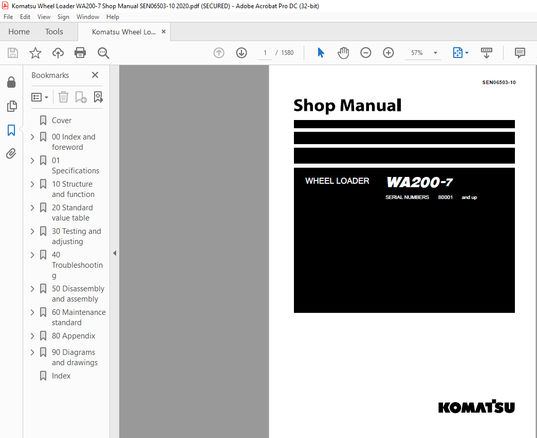
Komatsu WA200-7 Wheel Loader Shop Manual SEN06503-10 – PDF DOWNLOAD
SERIAL NUMBERS 80001 and up
How to read the shop manual
Composition of shop manual
q This shop manual describes the technical information required for the services performed in a workshop.
The shop manual is divided into the following chapters for the convenience of use.
00. Index and foreword
q This section includes the index, foreword, safety and basic information.
01. Specification
q This section explains the specifications of the machine.
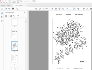
10. Structure and function
q This section explains the structure and function of the machine. The section of “Structure and function”
serves not only to give an understanding for the structure of each component, but also serves as reference
material for troubleshooting.
20. Standard value table
q The standard values for a new machine and trouble shooting are indicated. This standard value table is
used for testing and adjusting, and determining a failure at troubleshooting.
30. Testing and adjusting
q This section describes the measuring tools and how to measure, and how to adjust various parts. As for
the standard value and failure criterion, see the standard value table.
40. Troubleshooting
q This section describes the troubleshooting in a suspected area when a failure occurs and the remedy for
the failure. Troubleshooting is described by each failure mode.
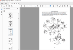
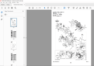
50. Disassembly and assembly
q This section explains the procedures for removing, installing, disassembling, and assembling each part or
component and the special tools for the works as well as precautions for doing them safely. In addition,
tightening torque, and quantity and weight of coating material, oil, grease, and coolant required for the
works are also explained.
60. Maintenance standard
q This section describes the maintenance standard values for each component. This section gives the criterion
values for each component and required remedy at disassembly or maintenance.
80. Appendix
q The structure and function, testing and adjusting, and troubleshooting for all of the other components or
equipment which can not be separately classified are explained together in the appendix.
90. Diagrams and drawings
q This section gives hydraulic circuit diagrams and electrical circuit diagrams.
IMAGES PREVIEW OF THE MANUAL:
More products