$47
Komatsu WA470-6R WA480-6R Wheel Loader Shop Manual SEN06594-05 – PDF DOWNLOAD
Komatsu WA470-6R WA480-6R Wheel Loader Shop Manual SEN06594-05 – PDF DOWNLOAD
FILE DETAILS:
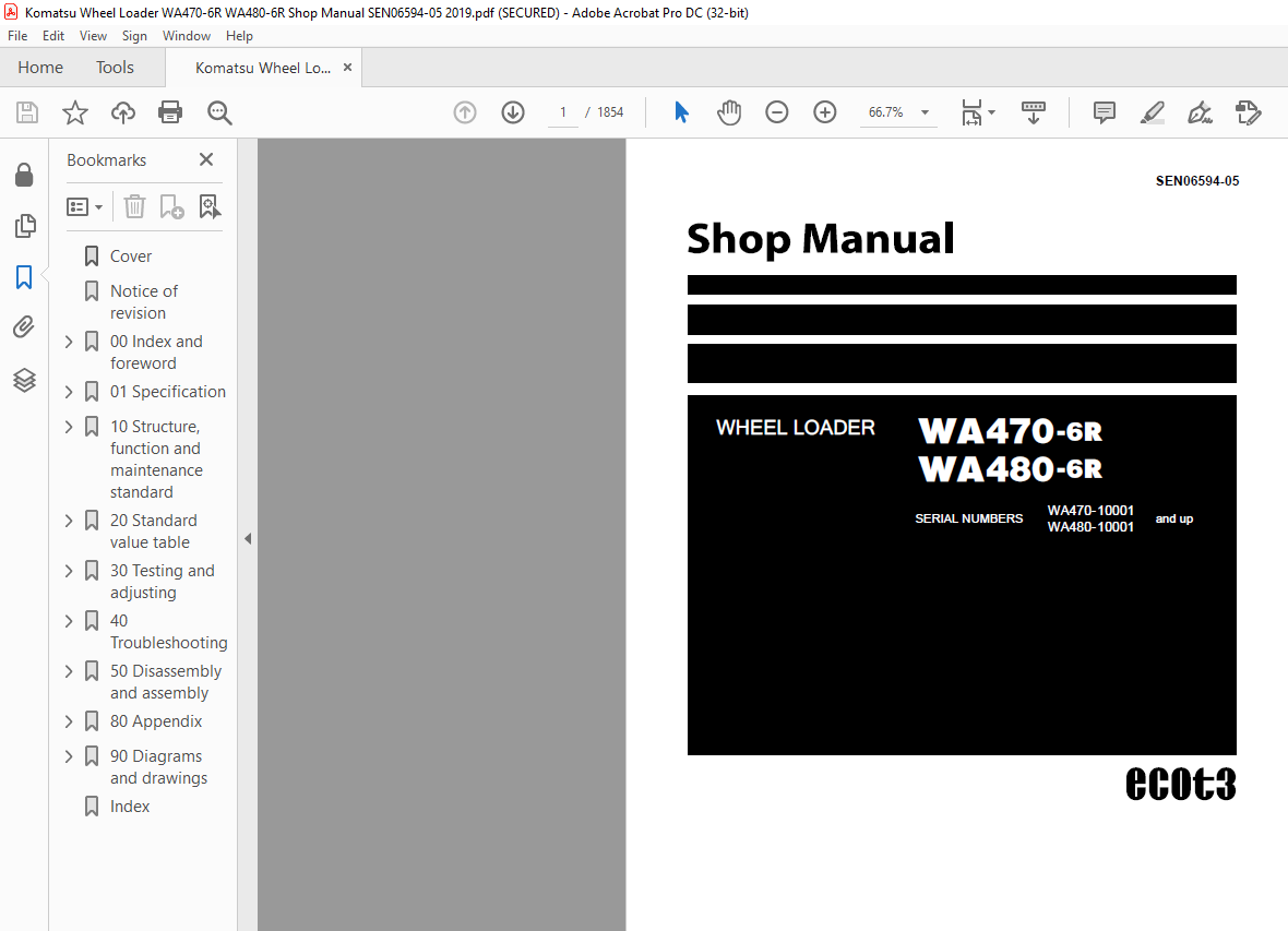
Komatsu WA470-6R WA480-6R Wheel Loader Shop Manual SEN06594-05 – PDF DOWNLOAD
Language : English
Pages : 1854
Downloadable : Yes
File Type : PDF
Size: 128 MB
TABLE OF CONTENTS:
Komatsu WA470-6R WA480-6R Wheel Loader Shop Manual SEN06594-05 – PDF DOWNLOAD
00 Index and foreword
Table of contents 00-2
Foreword and general information 00-15
Safety notice 00-15
How to read the shop manual 00-20
Explanation of terms for maintenance standard 00-22
Handling of electric equipment and hydraulic component 00-24
Handling of connectors newly used for engines 00-33
How to read electric wire code 00-36
Precautions when carrying out operation 00-39
Method of disassembling and connecting push-pull type coupler 00-42
Standard tightening torque table 00-45
Conversion table 00-49
01 Specification
Specification and technical data 01-3
Specification dimension drawing 01-3
Specifications 01-4
Weight table 01-8
Table of fuel, coolant and lubricants 01-10
10 Structure, function and maintenance standard
Engine and cooling system 10-4
Engine mount and transmission mount 10-4
Cooling system 10-5
Cooling fan pump 10-6
Cooling fan motor 10-14
Power train 10-21
Power train 10-21
Power train system diagram 10-22
Drive shaft 10-24
Power train piping diagram 10-25
Torque converter 10-26
Transmission 10-34
Transmission control valve 10-52
ECMV 10-56
Main relief valve and torque converter relief valve 10-68
Axle 10-70
Differential 10-74
Limited slip differential 10-79
Final drive 10-86
Steering system 10-92
Steering component layout drawing 10-92
Steering column 10-93
Steering pump 10-94
Steering valve 10-107
Orbit-roll valve 10-124
Stop valve 10-132
Steering relief valve 10-133
Steering cylinder 10-134
Emergency steering motor 10-136
Emergency steering pump 10-137
WA470-6R, WA480-6R 00-3
00 Index and foreword
Joystick steering lever linkage 10-138
Electrical steering lever 10-139
Joystick EPC valve 10-140
Brake system 10-142
Brake component layout drawing 10-142
Charge valve 10-143
Brake valve 10-150
Accumulator (for brake) 10-155
Slack adjuster 10-156
Brake 10-158
Parking brake control 10-163
Parking brake 10-164
Parking brake solenoid valve 10-166
Emergency parking brake release valve 10-168
Undercarriage and frame 10-170
Axle mount and center hinge pin 10-170
Tires 10-174
Hydraulic system 10-176
Hydraulic component layout drawing 10-176
Work equipment control lever linkage 10-179
Hydraulic tank 10-182
Power train pump 10-184
Work equipment pump 10-186
Work equipment control valve 10-206
CLSS 10-217
Each function and operation of each valve 10-222
PPC valve 10-236
Accumulator (for PPC circuit) 10-244
Accumulator (for power train circuit) 10-245
Accumulator (for ECSS) 10-246
Work equipment PPC cut-off solenoid valve 10-247
Work equipment 10-250
Work equipment linkage 10-250
Bucket 10-253
Bucket positioner and boom kick-out 10-254
Work equipment cylinder 10-260
Cab and its attachments 10-261
Cab 10-261
Air conditioner 10-262
Electrical system 10-280
Machine monitor system 10-280
Machine monitor 10-284
Electrical system (Transmission controller system) 10-316
Transmission controller 10-356
Electrical system (Work equipment controller system) 10-358
Work equipment controller 10-364
Electric transmission control 10-366
Kickdown switch and hold switch 10-370
Load meter cancel switch and load meter subtotal switch 10-370
Multi-function knob 10-371
Joystick steering knob 10-372
KOMTRAX system 10-374
Engine starting circuit 10-376
Engine stopping circuit 10-378
00-4 WA470-6R, WA480-6R
00 Index and foreword
Preheating circuit 10-379
Engine power mode selector circuit 10-380
Engine output derating function 10-381
Automatic warm-up function 10-381
Parking brake circuit 10-382
Sensor 10-384
20 Standard value table
Standard service value table 20-3
Standard value table for engine 20-3
Standard value table for chassis 20-4
30 Testing and adjusting
Related information on testing and adjusting 30-4
Tools for testing, adjusting, and troubleshooting 30-4
Testing engine speed 30-9
Engine and cooling system 30-9
Testing exhaust gas color 30-11
Testing exhaust temperature 30-13
Adjusting valve clearance 30-15
Testing compression pressure 30-17
Testing blow-by pressure 30-18
Testing engine oil pressure 30-19
Testing intake air (boost) pressure 30-20
Handling fuel system equipment 30-21
Releasing residual pressure in fuel system 30-21
Testing fuel pressure 30-22
Testing fuel return and leak amount 30-23
Bleeding air from fuel circuit 30-26
Testing fuel circuit for leakage 30-28
Handling of reduced cylinder mode operation 30-29
Handling of no injection cranking operation 30-29
Handling of controller voltage circuit 30-30
Check of muffler and muffler stack for looseness and damage 30-31
Check of muffler function 30-31
Check of installed condition of cylinder head and manifolds 30-32
Check of engine piping for damage and looseness 30-32
Testing and adjusting air conditioner compressor belt tension 30-33
Testing and adjusting alternator belt tension 30-34
Power train 30-35
Adjusting transmission speed sensor 30-35
Adjusting directional lever length 30-36
Adjusting gear shift lever length 30-36
Testing FNR lever and gear shift lever 30-37
Testing and adjusting power train oil pressure 30-38
Procedure for flushing torque converter and transmission hydraulic circuit 30-52
Method of moving machine when transmission valve is broken 30-54
Check of axle final drive for oil leakage 30-57
Check of drive shafts for looseness, play and damage 30-57
Steering system 30-58
Testing and adjusting steering stop valve 30-58
Testing and adjusting steering wheel 30-60
Testing steering oil pressure 30-62
Bleeding air from steering circuit 30-65
WA470-6R, WA480-6R 00-5
00 Index and foreword
Brake system 30-66
Testing brake pedal 30-66
Testing and adjusting brake pedal linkage 30-67
Testing brake performance 30-68
Testing and adjusting accumulator charge pressure 30-69
Testing wheel brake oil pressure 30-71
Testing wear of wheel brake disc 30-73
Bleeding air from wheel brake circuit 30-74
Releasing residual pressure in brake accumulator circuit 30-75
Testing parking brake performance 30-75
Testing parking brake oil pressure 30-76
Testing wear of parking brake disc 30-78
Manual release method for parking brake 30-79
Hydraulic system 30-80
Testing hydraulic drive fan 30-80
Adjustment of hydraulic fan speed sensor 30-82
Bleeding air from hydraulic drive fan circuit 30-83
Testing and adjusting work equipment control lever 30-85
Testing and adjusting work equipment PPC oil pressure 30-86
Testing and adjusting work equipment oil pressure 30-89
Bleeding air from work equipment circuit 30-93
Releasing residual pressure in work equipment circuit 30-94
Procedure for testing of nitrogen gas pressure and charging of nitrogen gas of ECSS (Electronically
Controlled Suspension System) accumulator 30-95
Procedure for testing of nitrogen gas pressure and charging of nitrogen gas of brake accumulator
30-101
Work equipment 30-106
Testing and adjusting bucket positioner 30-106
Testing and adjusting boom kick-out 30-108
Checking proximity switch operation pilot lamp 30-109
Electrical system 30-110
Procedure for testing diodes 30-110
Preparation work for troubleshooting for electrical system 30-111
How to start KOMTRAX terminal operations 30-116
Indicator lamps of KOMTRAX terminal 30-121
Adjusting replaced, reassembled or added sensor, controller, etc with machine monitor 30-124
Special functions of machine monitor (EMMS) 30-127
Pm-clinic 30-190
Pm-clinic inspection table 30-190
40 Troubleshooting
General information on troubleshooting 40-11
Points to remember when troubleshooting 40-11
How to proceed in troubleshooting 40-12
Testing before troubleshooting 40-14
Classification and procedures of troubleshooting 40-16
Failure code table 40-20
Information in troubleshooting table 40-31
Troubleshooting method for open circuit in wiring harness of pressure sensor system 40-33
Connection table for connector pin numbers 40-35
T- branch box and T- branch adapter table 40-71
Fuse locations 40-74
Phenomena looking like troubles and troubleshooting Nos 40-77
Information contained in troubleshooting table 40-80
00-6 WA470-6R, WA480-6R
(05)
00 Index and foreword
Troubleshooting by failure code (Display of code) 40-83
Failure code [1500L0] (TORQFLOW transmission: Double meshing) 40-83
Failure code [15SAL1] (ECMV F clutch: When command current is OFF, fill signal is ON) 40-84
Failure code [15SALH] (ECMV F clutch: When command current is ON, fill signal is OFF) 40-86
Failure code [15SBL1] (ECMV R clutch: When command current is OFF, fill signal is ON) 40-88
Failure code [15SBLH] (ECMV R clutch: When command current is ON, fill signal is OFF) 40-90
Failure code [15SEL1] (ECMV 1st clutch: When command current is OFF, fill signal is ON) 40-92
Failure code [15SELH] (ECMV 1st clutch: When command current is ON, fill signal is OFF) 40-94
Failure code [15SFL1] (ECMV 2nd clutch: When command current is OFF, fill signal is ON) 40-96
Failure code [15SFLH] (ECMV 2nd clutch: When command current is ON, fill signal is OFF) 40-98
Failure code [15SGL1] (ECMV 3rd clutch: When command current is OFF, fill signal is ON) 40-100
Failure code [15SGLH] (ECMV 3rd clutch: When command current is ON, fill signal is OFF) 40-102
Failure code [15SHL1] (ECMV 4th clutch: When command current is OFF, fill signal is ON) 40-104
Failure code [15SHLH] (ECMV 4th clutch: When command current is ON, fill signal is OFF) 40-106
Failure code [2F00MA] (Parking brake: Malfunction) 40-108
Failure code [2G43ZG] (Accumulator: Low oil pressure) 40-110
Failure code [44K0L4] (Bucket positioner: ON/OFF signals disagree) 40-112
Failure code [AA1ANX] (Air cleaner: Clogging) 40-116
Failure code [AB00L6] (Alternator: Signal disagrees with operating state of engine) 40-118
Failure code [AB00MA] (Alternator: Malfunction) 40-120
Failure code [B@BAZG] (Rotation derating by low engine oil pressure) 40-122
Failure code [B@BAZK] (Engine oil: Low level) 40-125
Failure code [B@BCNS] (Coolant: Overheating) 40-126
Failure code [B@BCZK] (Coolant: Low level) 40-128
Failure code [B@C7NS] (Brake oil: Overheating) 40-130
Failure code [b@CENS] (Torque converter oil: Overheating) 40-132
Failure code [B@CENS] (Torque converter oil: Overheating) 40-134
Failure code [B@HANS] (Hydraulic oil: Overheating) 40-136
Failure code [CA111] (Abnormality in engine controller) 40-138
Failure code [CA115] (Engine Ne or Bkup speed sensor error) 40-141
Failure code [CA122] Chg Air Press Sensor High Error 40-142
Failure code [CA123] Chg Air Press Sensor Low Error 40-144
Failure code [CA131] Throttle sensor : High error 40-146
Failure code [CA132] Throttle sensor : Low error 40-148
Failure code [CA135] Eng Oil Press Sensor High Error 40-150
Failure code [CA141] Eng Oil Press Sensor Low Error 40-152
Failure code [CA144] Coolant Temp Sens High Error 40-154
Failure code [CA145] Coolant Temp Sens Low Error 40-156
Failure code [CA153] Chg Air Temp Sensor High Error 40-158
Failure code [CA154] Chg Air Temp Sensor Low Error 40-160
Failure code [CA187] Sens Supply 2 Volt Low Error 40-162
Failure code [CA221] Ambient Press Sens High Error 40-164
Failure code [CA222] Ambient Press Sens Low Error 40-166
Failure code [CA227] Sens Supply 2 Volt High Error 40-168
Failure code [CA234] Eng Overspeed 40-169
Failure code [CA238] Ne Speed Sens Supply Volt Error 40-170
Failure code [CA263] Fuel Temp Sensor High Error 40-172
Failure code [CA265] Fuel Temp Sensor Low Error 40-174
Failure code [CA271] IMV/PCV1 Short Error 40-176
Failure code [CA272] IMV/PCV1 Open Error 40-178
Failure code [CA273] PCV2 Short Error 40-180
Failure code [CA274] PCV2 Open Error 40-182
Failure code [CA322] Inj #1(L#1) Open/Short Error 40-184
Failure code [CA323] Inj #5 (L#5) Open/Short Error 40-186
WA470-6R, WA480-6R 00-7
(05)
00 Index and foreword
Failure code [CA324] Inj #3(L#3) Open/Short Error 40-188
Failure code [CA325] Inj #6 (L#6) Open/Short Error 40-190
Failure code [CA331] Inj #2(L#2) Open/Short Error 40-192
Failure code [CA332] Inj #4 (L#4) Open/Short Error 40-194
Failure code [CA342] (Calibration code inconsistency) 40-196
Failure code [CA351] Injectors Drive Circuit Error 40-197
Failure code [CA352] Sens Supply 1 Volt Low Error 40-198
Failure code [CA386] Sens Supply 1 Volt High Error 40-200
Failure code [CA431] Idle validation switch : Error 40-201
Failure code [CA432] Idle validation switch : Action error 40-204
Failure code [CA441] (Battery voltage low error) 40-206
Failure code [CA442] (Battery voltage high error) 40-208
Failure code [CA449] Rail Press Very High Error 40-210
Failure code [CA451] Rail Press Sensor High Error 40-212
Failure code [CA452] Rail Press Sensor Low Error 40-214
Failure code [CA553] (Common rail pressure high error 1) 40-216
Failure code [CA554] (Common rail pressure sensor in-range error) 40-217
Failure code [CA559] (Supply pump pressure very low error) 40-218
Failure code [CA689] Eng Ne Speed Sensor Error 40-222
Failure code [CA731] (Engine Bkup speed sensor phase error) 40-224
Failure code [CA757] (All continuous data lost error) 40-225
Failure code [CA778] Eng Bkup Speed Sensor Error 40-226
Failure code [CA1633] KOMNET Datalink Timeout Error 40-228
Failure code [CA2185] Throttle sensor power supply voltage : High error 40-230
Failure code [CA2186] Throttle sensor power supply voltage : Low error 40-232
Failure code [CA2249] (Supply pump pressure very low error 2) 40-234
Failure code [CA2555] Intake heater relay : Open circuit 40-236
Failure code [CA2556] Intake heater relay : Short circuit 40-238
Failure code [D150KA] (Emergency steering relay: Disconnection) 40-240
Failure code [D150KB] (Emergency steering relay: Short circuit) 40-242
Failure code [D150KY] (Emergency steering relay: Short circuit with power supply line) 40-244
Failure code [D160KA] (Backup lamp relay output: Disconnection) 40-246
Failure code [D160KB] (Backup lamp relay output: Short circuit) 40-248
Failure code [D191KA] (Joystick steering neutral safety relay: Disconnection) 40-250
Failure code [D191KB] (Joystick steering neutral safety relay: Short circuit) 40-252
Failure code [D191KY] (Joystick steering neutral safety relay: Short circuit with power supply line)
40-254
Failure code [D192KA] (ECSS solenoid: Disconnection) 40-256
Failure code [D192KB] (ECSS solenoid: Short circuit) 40-257
Failure code [D192KY] (ECSS solenoid: Short circuit with power supply line) 40-258
Failure code [D193KA] (Joystick steering solenoid cut-off relay: Disconnection) 40-260
Failure code [D193KB] (Joystick steering solenoid cut-off relay: Short circuit) 40-262
Failure code [D193KY] (Joystick steering solenoid cut-off relay: Short circuit with power supply line)
40-264
Failure code [D5ZHKA] (Terminal C signal: Disconnection) 40-267
Failure code [D5ZHKB] (Terminal C signal: Short circuit) 40-271
Failure code [D5ZHKZ] (Terminal C signal: Disconnection or short circuit) 40-274
Failure code [D5ZHL6] (Terminal C signal: Signal does not match engine running or stopped state)
40-279
Failure code [DA80L4] (Auto grease controller: ON/OFF signals disagree) 40-282
Failure code [DAF3KK] (Machine monitor: Low source voltage (input)) 40-284
Failure code [DAF5KP] (Machine monitor: Low output voltage) 40-286
Failure code [DAFRKR] (CAN communication with machine monitor: Defective communication
(Abnormality in target component system)) 40-288
00-8 WA470-6R, WA480-6R
(05)
00 Index and foreword
Failure code [DAQ0KK] (Transmission controller: Low source voltage) 40-290
Failure code [DAQ0KT] (Transmission controller: Abnormality in controller) 40-292
Failure code [DAQ1KA] (Terminal ACC input: Disconnection) 40-293
Failure code [DAQ2KK] (Transmission controller load power supply line: Low source voltage (input))
40-296
Failure code [DAQ9KQ] (Transmission controller model selection: Disagreement of model selection
signals) 40-298
Failure code [DAQRKR] (CAN communication with transmission controller: Defective communication
(Abnormality in target component system)) 40-299
Failure code [DAQRMA] (Transmission controller option setting: Malfunction) 40-304
Failure code [DB2RKR] (CAN communication with engine controller: Defective communication
(Abnormality in target component system) 40-305
Failure code [DB90KK] Work equipment controller: Low source voltage (input) 40-312
Failure code [DB90KT] Work equipment controller: Abnormality in controller 40-314
Failure code [DB92KK] Work equipment controller load power supply line: Low source voltage (input)
40-316
Failure code [DB95KX] Work equipment controller power supply output: Out of input signal range
40-319
Failure code [DB99KQ] (Work equipment controller model selection: Disagreement in model selection
signals) 40-322
Failure code [DB9RKR] CAN communication with work equipment controller: Defective communication
(Abnormality in target component system) 40-323
Failure code [DB9RMA] (Work equipment controller option setting: Malfunction) 40-328
Failure code [DB9RMC] (CAN communication with transmission controller, engine controller and
machine monitor: Defective operation) 40-329
Failure code [DD15LD] ■ switch (Panel switch 1): Switch is kept pressed for long time 40-330
Failure code [DD16LD] U switch (Panel switch 2): Switch is kept pressed for long time 40-332
Failure code [DD17LD] < switch (Panel switch 3): Switch is kept pressed for long time 40-334
Failure code [DD18LD] > switch (Panel switch 4): Switch is kept pressed for long time 40-336
Failure code [DD1ALD] Remote positioner raise/lower set switch (raise): Switch is kept pressed for long
time 40-338
Failure code [DD1BLD] Remote positioner raise/lower set switch (lower): Switch is kept pressed for long
time 40-340
Failure code [DD1CLD] Load meter subtotal switch: Switch is kept pressed for long time 40-342
Failure code [DD1FLD] Load meter mode selector switch (A/B): Switch is kept pressed for long time
40-344
Failure code [DD1GLD] Load meter mode selector switch (+/–): Switch is kept pressed for long time
40-346
Failure code [DD1HLD] (Load meter display selector switch: Switch is kept pressed for long time)
40-348
Failure code [DD1NLD] (Fan reverse switch: Switch is kept pressed for long time) 40-350
Failure code [DD1NL4] (Fan automatic reverse switch: Switch is kept pressed for long time) 40-352
Failure code [DDB6L4] (Parking brake switch (Neutralizer): ON/OFF signals disagree) 40-354
Failure code [DDD1LD] (Remote positioner bucket angle set switch: Switch is kept pressed for long
time) 40-358
Failure code [DDE5MA] (Emergency steering drive switch: Malfunction) 40-360
Failure code [DDK3KA] (Right FNR switch: Disconnection) 40-362
Failure code [DDK4KA] (Joystick steering FNR switch: Disconnection) 40-365
Failure code [DDK5L4] (Joystick steering shift-up/down switch: ON/OFF signals disagree) 40-368
Failure code [DDK6KA] (FNR lever switch: Disconnection) 40-370
Failure code [DDK6KB] (FNR lever switch: Short circuit) 40-374
Failure code [DDS5KA] (Steering pressure switch signal: Disconnected) 40-376
Failure code [DDS5KB] (Steering pressure switch signal: Short circuit) 40-378
Failure code [DDS5L6] (Steering: Low oil pressure) 40-380
WA470-6R, WA480-6R 00-9
(05)
00 Index and foreword
Failure code [DDT0L4] (Shift mode selector switch: ON/OFF signals disagree) 40-382
Failure code [DDT4LD] (Transmission cut-off set switch: Switch is kept pressed for long time) 40-384
Failure code [DDW9LD] (Kick-down switch: Switch is kept pressed for long time) 40-386
Failure code [DDWLLD] (Hold switch: Switch is kept pressed for long time) 40-388
Failure code [DDY0LD] (Load meter cancel switch: Switch is kept pressed for long time) 40-390
Failure code [DF10KA] (Transmission shift lever switch: Disconnected) 40-392
Failure code [DF10KB] (Transmission shift lever switch: Short circuit) 40-396
Failure code [DGF1KA] (Transmission oil temperature sensor: Disconnected) 40-400
Failure code [DGF1KB] (Transmission oil temperature sensor: Short circuit) 40-402
Failure code [DGH2KX] (Hydraulic oil temperature sensor: Out of input signal range) 40-404
Failure code [DGR2KA] (Rear brake oil temperature sensor: Disconnected) 40-406
Failure code [DGR2KX] (Rear brake oil temperature sensor: Out of input signal range) 40-408
Failure code [DGT1KX] (Torque converter oil temperature sensor: Out of input signal range) 40-410
Failure code [DH21KA] (Loader pump pressure sensor: Disconnection) 40-412
Failure code [DH21KB] (Loader pump pressure sensor: Power supply line short) 40-414
Failure code [DHPCKX] (Boom cylinder bottom pressure sensor: Out of input signal range) 40-416
Failure code [DHPDKX] (Boom cylinder head pressure sensor: Out of input signal range) 40-418
Failure code [DHT1KX] (Transmission cut-off pressure sensor: Out of input signal range) 40-420
Failure code [DHT8KA] (Steering pump pressure sensor: Disconnection) 40-422
Failure code [DHT8KB] (Steering pump pressure sensor: Short circuit) 40-424
Failure code [DK59KA] (Lift arm EPC lever potentiometer (Main): Disconnection) 40-426
Failure code [DK59KY] (Lift arm EPC lever potentiometer (Main): Short circuit with power supply line)
40-429
Failure code [DK59L8] (Lift arm EPC lever potentiometer (Main): Analog signals disagree) 40-432
Failure code [DK5AKA] (Lift arm EPC lever potentiometer (Sub): Disconnection) 40-435
Failure code [DK5AKY] (Lift arm EPC lever potentiometer (Sub): Short circuit with power supply line)
40-438
Failure code [DK5BKA] (Bucket EPC lever potentiometer (Main): Disconnection) 40-441
Failure code [DK5BKY] (Bucket EPC lever potentiometer (Main): Short circuit with power supply line)
40-444
Failure code [DK5BL8] (Bucket EPC lever potentiometer (Main): Analog signals disagree) 40-447
Failure code [DK5CKA] (Bucket EPC lever potentiometer (Sub): Disconnection) 40-450
Failure code [DK5CKY] (Bucket EPC lever potentiometer (Sub): Short circuit with power supply line)
40-453
Failure code [DK5FKA] (Joystick steering EPC lever potentiometer (Main): Disconnection) 40-456
Failure code [DK5FKY] (Joystick steering EPC lever potentiometer (Main): Short circuit with power
supply line) 40-460
Failure code [DK5FL8] (Joystick steering EPC lever potentiometer (Main): Analog signals disagree)
40-462
Failure code [DK5GKA] (Joystick steering EPC lever potentiometer (Sub): Disconnection) 40-465
Failure code [DK5GKY] (Joystick steering EPC lever potentiometer (Sub): Short circuit with power
supply line) 40-468
Failure code [DKA0KA] (Lift arm angle sensor: Disconnection) 40-470
Failure code [DKA0KX] (Lift arm angle sensor: Out of input signal range) 40-471-1
Failure code [DKA0KY] (Lift arm angle sensor: Short circuit with power supply line) 40-472
Failure code [DKA0L0] (Lift arm angle sensor: Double meshing) 40-474
Failure code [DLF1KA] (Transmission input speed sensor: Disconnection) 40-476
Failure code [DLF1LC] (Transmission input speed sensor: Short circuit) 40-477
Failure code [DLM3KA] (Fan speed sensor: Disconnection) 40-478
Failure code [DLM3LC] (Fan speed sensor: Short circuit) 40-480
Failure code [DLT3KA] (Transmission output speed sensor: Disconnection) 40-482
Failure code [DLT3LC] (Transmission output speed sensor: Out of input signal range) 40-484
Failure code [DT20KB] (Transmission cut-off indicator lamp: Short circuit) 40-486
Failure code [DUM1KB] (Remote positioner raise set indicator lamp: Short circuit) 40-488
00-10 WA470-6R, WA480-6R
(05)
00 Index and foreword
Failure code [DUM2KB] (Remote positioner lower set indicator lamp: Short circuit) 40-490
Failure code [DV00KB] (Alarm buzzer: Short circuit) 40-492
Failure code [DW4PKA] (Lift arm raise EPC solenoid: Disconnection) 40-494
Failure code [DW4PKB] (Lift arm raise EPC solenoid: Short circuit) 40-496
Failure code [DW4PKY] (Lift arm raise EPC solenoid: Short circuit with power supply line) 40-498
Failure code [DW4QKA] (Lift arm lower EPC solenoid: Disconnection) 40-500
Failure code [DW4QKB] (Lift arm lower EPC solenoid: Short circuit) 40-501
Failure code [DW4QKY] (Lift arm lower EPC solenoid: Short circuit with power supply line) 40-502
Failure code [DW4RKA] (Bucket tilt EPC solenoid: Disconnection) 40-504
Failure code [DW4RKB] (Bucket tilt EPC solenoid: Short circuit) 40-505
Failure code [DW4RKY] (Bucket tilt EPC solenoid: Short circuit with power supply line) 40-506
Failure code [DW4SKA] (Bucket dump EPC solenoid: Disconnection) 40-508
Failure code [DW4SKB] (Bucket dump EPC solenoid: Short circuit) 40-509
Failure code [DW4SKY] (Bucket dump EPC solenoid: Short circuit with power supply line) 40-510
Failure code [DW7BKA] (Fan reverse solenoid: Disconnection) 40-512
Failure code [DW7BKB] (Fan reverse solenoid: Short circuit) 40-513
Failure code [DW7BKY] (Fan reverse solenoid: Short circuit with power supply line) 40-514
Failure code [DWM1KA] (Work equipment neutral lock solenoid: Disconnection) 40-516
Failure code [DWM1KB] (Work equipment neutral lock solenoid: Short circuit) 40-518
Failure code [DWM1KY] (Work equipment neutral lock solenoid: Short circuit with power supply line)
40-520
Failure code [DWN6KA] (Lift arm raise magnet detent solenoid: Disconnection) 40-522
Failure code [DWN6KB] (Lift arm raise magnet detent solenoid: Short circuit) 40-524
Failure code [DWN6KY] (Lift arm raise magnet detent solenoid: Short circuit with power supply line)
40-526
Failure code [DWN7KA] (Lift arm float magnet detent solenoid: Disconnection) 40-528
Failure code [DWN7KB] (Lift arm float magnet detent solenoid: Short circuit) 40-530
Failure code [DWN7KY] (Lift arm float magnet detent solenoid: Short circuit with power supply line)
40-532
Failure code [DWN8KA] (Bucket tilt magnet detent solenoid: Disconnection) 40-534
Failure code [DWN8KB] (Bucket tilt magnet detent solenoid: Short circuit) 40-536
Failure code [DWN8KY] (Bucket tilt magnet detent solenoid: Shorted with the power source) 40-538
Failure code [DX16KA] (Fan pump EPC solenoid: Disconnection) 40-540
Failure code [DX16KB] (Fan pump EPC solenoid: Short circuit) 40-541
Failure code [DX16KY] (Fan pump EPC solenoid: Short circuit with power supply line) 40-542
Failure code [DXA1KA] (Loader pump PC-EPC solenoid: Disconnection) 40-544
Failure code [DXA1KB] (Loader pump PC-EPC solenoid: Short circuit) 40-546
Failure code [DXANKA] (Steering pump PC-EPC solenoid: Disconnection) 40-548
Failure code [DXANKB] (Steering pump PC-EPC solenoid: Short circuit) 40-550
Failure code [DXH1KA] (Lockup ECMV solenoid: Disconnection) 40-552
Failure code [DXH1KB] (Lockup ECMV solenoid: Short circuit) 40-554
Failure code [DXH1KY] (Lockup ECMV solenoid: Short circuit with power supply line) 40-556
Failure code [DXH4KA] (1st clutch ECMV solenoid: Disconnection) 40-558
Failure code [DXH4KB] (1st clutch ECMV solenoid: Short circuit) 40-560
Failure code [DXH4KY] (1st clutch ECMV solenoid: Short circuit with power supply line) 40-562
Failure code [DXH5KA] (2nd clutch ECMV solenoid: Disconnection) 40-564
Failure code [DXH5KB] (2nd clutch ECMV solenoid: Short circuit) 40-566
Failure code [DXH5KY] (2nd clutch ECMV solenoid: Short circuit with power supply line) 40-568
Failure code [DXH6KA] (3rd clutch ECMV solenoid: Disconnection) 40-570
Failure code [DXH6KB] (3rd clutch ECMV solenoid: Short circuit) 40-572
Failure code [DXH6KY] (3rd clutch ECMV solenoid: Short circuit with power supply line) 40-574
Failure code [DXH7KA] (R clutch ECMV solenoid: Disconnection) 40-576
Failure code [DXH7KB] (R clutch ECMV solenoid: Short circuit) 40-578
Failure code [DXH7KY] (R clutch ECMV solenoid: Short circuit with power supply line) 40-580
WA470-6R, WA480-6R 00-11
(05)
00 Index and foreword
Failure code [DXH8KA] (F clutch ECMV solenoid: Disconnection) 40-582
Failure code [DXH8KB] (F clutch ECMV solenoid: Short circuit) 40-584
Failure code [DXH8KY] (F clutch ECMV solenoid: Short circuit with power supply line) 40-586
Failure code [DXHHKA] (4th clutch ECMV solenoid: Disconnection) 40-588
Failure code [DXHHKB] (4th clutch ECMV solenoid: Short circuit) 40-590
Failure code [DXHHKY] (4th clutch ECMV solenoid: Short circuit with power supply line) 40-592
Failure code [DXHLKA] (Joystick steering right EPC solenoid: Disconnection) 40-594
Failure code [DXHLKB] (Joystick steering right EPC solenoid: Short circuit) 40-596
Failure code [DXHLKY] (Joystick steering right EPC solenoid: Short circuit with power supply line)
40-598
Failure code [DXHMKA] (Joystick steering left EPC solenoid: Disconnection) 40-600
Failure code [DXHMKB] (Joystick steering left EPC solenoid: Short circuit) 40-602
Failure code [DXHMKY] (Joystick steering left EPC solenoid: Short circuit with power supply line)
40-604
Failure code [DY30MA] Motor-driven emergency steering pump failure (During operation of machine)
40-606
Failure code [DY30MC] Motor-driven emergency steering pump failure (Malfunction in manual mode)
40-609
Failure code [DY30ME] Emergency steering: Operating for more than 1 minute 40-612
Troubleshooting of electrical system (E-mode) 40-615
Installing positions of fuses 40-615
Information in troubleshooting table 40-618
E-1 Engine does not start 40-620
E-2 Wiper does not operate 40-626
E-3 Windshield washer does not operate 40-630
E-4 Headlamp, clearance lamp, tail lamp, and license lamp do not light up or go off 40-633
E-5 Working lamp does not light up or go off 40-641
E-6 Turn signal lamp and hazard lamp do not light up or go off 40-646
E-7 Brake lamp does not light or it keeps lighting up 40-652
E-8 Backup lamp does not light or it keeps lighting up 40-654
E-9 Backup buzzer does not sound or it keeps sounding 40-656
E-10 Horn does not sound or it keeps sounding 40-658
E-11 Alarm buzzer does not sound or it keeps sounding 40-660
E-12 Air conditioner does not operate or stop 40-662
E-13 The KOMTRAX system does not work properly 40-666
E-14 When kick-down switch is turned ON, kick-down operation does not start 40-668
E-15 When hold switch is pressed, holding operation does not start 40-670
E-16 Transmission is kept in neutral, or brake drags when directional lever is operated while parking
brake is applied 40-672
E-17 Transmission cut-off mode cannot be set or reset 40-674
E-18 Transmission cut-off set cannot be reset 40-676
E-19 FNR switch mode cannot be set or reset 40-678
E-20 Fan reverse function cannot be used or reset 40-680
E-21 Discharge from loader pump does not rise from minimum level 40-682
E-22 ECSS function cannot be used or reset 40-684
E-23 When parking brake is turned ON, parking brake indicator lamp does not light up 40-686
E-24 When emergency brake operates, brake oil pressure caution lamp does not operate 40-690
E-25 Air cleaner clogging indicator lamp does not light up 40-692
E-26 Radiator coolant level caution lamp does not light up 40-694
E-27 Hydraulic oil temperature gauge does not rise and hydraulic oil temperature caution lamp does not
light up 40-695
E-28 Torque converter oil temperature gauge does not rise and torque converter oil temperature caution
lamp does not light up 40-696
E-29 Steering oil pressure caution lamp does not light up 40-698
00-12 WA470-6R, WA480-6R
(05)
00 Index and foreword
E-30 Abnormality in t switch (panel switch 1) input 40-700
E-31 Abnormality in U switch (panel switch 1) input 40-702
E-32 Abnormality in < switch (panel switch 2) input 40-704
E-33 Abnormality in > switch (panel switch 2) input 40-706
E-34 When starting switch is turned to ON position, machine monitor displays nothing 40-708
Troubleshooting of hydraulic and mechanical system (H-mode) 40-710
Method of using troubleshooting chart 40-710
Table of failure and causes 40-712
H-1 The machine does not start 40-716
H-2 Torque converter lockup is not switched off (engine stalls) [Machine with lockup clutch (if equipped)]
40-718
H-3 Torque converter lockup is not switched on [Machine with lockup clutch (if equipped)] 40-719
H-4 The travel speed is slow, the thrusting force is weak, the uphill traveling power is weak, and the gear
is not shifted 40-720
H-5 Shocks are large at the times of starting and shifting gear 40-722
H-6 Time lag is large at the times of starting and shifting gear 40-724
H-7 The torque converter oil temperature is high 40-726
H-8 Steering does not turn 40-727
H-9 Steering does not turn [Machine with joystick steering (if equipped)] 40-728
H-10 Steering response is poor 40-729
H-11 Turning, response of steering is poor [machine with joystick steering (if equipped)] 40-730
H-12 Steering is heavy 40-731
H-13 When machine turns, it shakes or makes large shocks 40-732
H-14 When machine turns, it shakes or makes large shocks [machine with joystick steering (if
equipped)] 40-733
H-15 The wheel brake does not work or does not work well 40-734
H-16 The wheel brake is not released or it drags 40-735
H-17 The parking brake does not work or does not work well 40-736
H-18 The parking brake is not released or it drags (including emergency release system) 40-737
H-19 Lift arm does not rise 40-738
H-20 Lift arm speed is low or rising force of lift arm is insufficient 40-739
H-21 When rising, the lift arm comes to move slowly at specific height 40-740
H-22 The lift arm cylinder cannot hold down the bucket (Bucket floats) 40-740
H-23 Hydraulic drift of the lift arm is large 40-740
H-24 The lift arm wobbles during operation 40-740
H-25 Bucket does not tilt back 40-741
H-26 Bucket speed is low or tilting back force is insufficient 40-742
H-27 The bucket comes to operate slowly in the midst of tilting-back 40-743
H-28 The bucket cylinder cannot hold down the bucket 40-743
H-29 Hydraulic drift of the bucket is large 40-743
H-30 The bucket wobbles during travel with cargo (The work equipment valve is set to “HOLD”)
40-743
H-31 Lift arm and bucket control levers do not move smoothly and are heavy 40-744
H-32 During operation of the machine, engine speed lowers remarkably or engine stalls 40-745
H-33 Large shock is made when work equipment starts and stops 40-745
H-34 When work equipment circuit is relieved singly, other work equipment moves 40-745
H-35 ECSS does not operate, and pitching, bouncing occur 40-746
Troubleshooting of engine (S-mode) 40-747
Method of using troubleshooting chart 40-747
S-1 Engine is hard to start 40-750
S-2 Engine does not start 40-751
S-3 Engine does not pick up smoothly 40-754
S-4 Engine stops during operation 40-755
S-5 Engine does not rotate smoothly 40-756
WA470-6R, WA480-6R 00-13
(05)
00 Index and foreword
S-6 Engine lacks output (or lacks power) 40-757
S-7 Exhaust gas color is black (incomplete combustion) 40-758
S-8 Oil consumption is excessive (or exhaust gas color is blue) 40-759
S-9 Oil gets contaminated prematurely 40-760
S-10 Fuel consumption is excessive 40-761
S-11 Coolant contains oil (blows back or reduces) 40-762
S-12 Oil pressure drops 40-763
S-13 Oil level rises (Water, fuel in oil) 40-764
S-14 Coolant temperature rises too high (overheat) 40-765
S-15 Abnormal noise comes out 40-766
S-16 Vibration is excessive 40-767
50 Disassembly and assembly
General information on disassembly and assembly 50-4
How to read this manual 50-4
Coating materials list 50-6
Special tools list 50-9
Sketches of special tools 50-14
Engine and cooling system 50-35
Removal and installation of engine assembly 50-35
Removal and installation of engine hood assembly 50-39
Removal and installation of radiator assembly 50-42
Removal and installation of aftercooler assembly 50-45
Removal and installation of oil cooler assembly 50-47
Removal and installation of cooling fan and drive motor assembly 50-49
Removal and installation of fuel supply pump assembly 50-53
Removal and installation of fuel injector assembly 50-59
Removal and installation of cylinder head assembly 50-65
Removal and installation of engine front oil seal 50-71
Removal and Installation of engine rear oil seal 50-74
Removal and installation of fuel tank assembly 50-79
Power train 50-82
Removal and installation of torque converter and transmission assembly 50-82
Disassembly and assembly of torque converter and transmission assembly 50-87
Disassembly and assembly of torque converter assembly (Standard specification) 50-120
Disassembly and assembly of torque converter assembly (Lockup specification) 50-125
Disassembly and assembly of clutch pack assembly 50-133
Removal and installation of front axle assembly 50-159
Removal and installation of rear axle assembly 50-161
Disassembly and assembly of axle housing assembly 50-167
Disassembly and assembly of differential assembly 50-176
Brake system 50-195
Removal and installation of parking brake disc and plate 50-195
Undercarriage and frame 50-198
Removal and installation of center hinge pin 50-198
Removal and installation of counterweight 50-206
Hydraulic system 50-208
Removal and installation of steering demand valve assembly 50-208
Removal and installation of work equipment valve assembly 50-211
Removal and installation of brake charge valve assembly 50-214
Removal and installation of hydraulic tank assembly 50-215
Removal and installation of steering and power train pump assembly 50-217
Removal and installation of work equipment and cooling fan pump assembly 50-218
Disassembly and assembly of hydraulic cylinder assembly 50-220
00-14 WA470-6R, WA480-6R
(05)
00 Index and foreword
Work equipment 50-228
Removal and installation of work equipment assembly 50-228
Cab and its attachments 50-232
Removal and installation of operator’s cab and floor frame assembly 50-232
Removal and installation of operator’s cab glass (stuck glass) 50-236
Disassembly and assembly of operator’s seat assembly 50-244
Removal and installation of air conditioner unit assembly 50-286
Electrical system 50-290
Removal and installation of engine controller assembly 50-290
Removal and installation of transmission controller assembly 50-291
Removal and installation of KOMTRAX terminal assembly 50-292
80 Appendix
Air conditioner 80-3
Precautions for refrigerant 80-3
Troubleshooting procedure 80-4
Circuit diagram and arrangement of connector pins 80-6
System diagram 80-11
Detail of air conditioner unit 80-13
Parts and connectors layout 80-15
Testing with self-diagnosis function (indication on control panel) 80-19
Testing temperature control 80-22
Testing vent (mode) changeover 80-23
Testing Fresh/Recirc changeover 80-25
Testing inside air temp sensor and outside air temp sensor 80-27
Testing evaporator temperature sensor 80-29
Testing sunlight sensor 80-30
Testing relays 80-31
Troubleshooting chart 1 80-32
Troubleshooting chart 2 80-33
Information in troubleshooting table 80-36
Troubleshooting for power supply system (Air conditioner does not operate) 80-37
Troubleshooting for compressor and refrigerant system (Air is not cooled) 80-40
Troubleshooting for blower motor system (No air comes out or air flow is abnormal) 80-43
Troubleshooting for temperature control 80-49
Troubleshooting for vent (mode) changeover 80-52
Troubleshooting for Fresh/Recirc air changeover 80-55
Troubleshooting with gauge pressure 80-57
Connection of service tool 80-59
Handling of compressor oil 80-60
90 Diagrams and drawings
Hydraulic diagrams and drawings 90-3
Symbols used in hydraulic circuit diagrams 90-3
Power train hydraulic circuit diagram 90-6
Automatic greasing circuit diagram 90-8
Hydraulic circuit diagram 90-11
Electrical diagrams and drawings 90-13
Symbols used in electric circuit diagrams 90-13
Electrical circuit diagram 90-17
Connector list and stereogram 90-39
Index 1
DESCRIPTION:
Komatsu WA470-6R WA480-6R Wheel Loader Shop Manual SEN06594-05 – PDF DOWNLOAD
SERIAL NUMBERS
WA470-10001 and up
WA480-10001 and up
How to read the shop manual 1
1. Composition of shop manual
This shop manual contains the necessary technical information for services performed in a workshop.
For ease of understanding, the manual is divided into the following sections.
00. Index and foreword
This section explains the shop manuals list, table of contents, safety, and basic information.
01. Specification
This section explains the specifications of the machine.
10. Structure, function and maintenance standard
This section explains the structure, function, and maintenance standard values of each component.
The structure and function sub-section explains the structure and function of each component. It
serves not only to give an understanding of the structure, but also serves as reference material for
troubleshooting. The maintenance standard sub-section explains the criteria and remedies for disassembly
and service.
20. Standard value table
This section explains the standard values for new machine and judgement criteria for testing,
adjusting, and troubleshooting. This standard value table is used to check the standard values in
testing and adjusting and to judge parts in troubleshooting.
30. Testing and adjusting
This section explains measuring instruments and measuring methods for testing and adjusting, and
method of adjusting each part. The standard values and judgement criteria for testing and adjusting
are explained in Testing and adjusting.
40. Troubleshooting
This section explains how to find out failed parts and how to repair them. The troubleshooting is
divided by failure modes. The “S mode” of the troubleshooting related to the engine may be also
explained in the Chassis volume and Engine volume. In this case, see the Chassis volume.
50. Disassembly and assembly
This section explains the special tools and procedures for removing, installing, disassembling, and
assembling each component, as well as precautions for them. In addition, tightening torque and
quantity and weight of coating material, oil, grease, and coolant necessary for the work are also
explained.
90. Diagrams and drawings (chassis volume)/Repair and replacement of parts (engine volume)
q Chassis volume
This section gives hydraulic circuit diagrams and electrical circuit diagrams.
q Engine volume
This section explains the method of reproducing, repairing, and replacing parts.
IMAGES PREVIEW OF THE MANUAL:


More products